2018-2020 Chevrolet Equinox Service & Repair Manual
What's Included?
Lifetime Access
Fast Download Speeds
Online & Offline Access
Access PDF Contents & Bookmarks
Full Search Facility
Print one or all pages of your manual
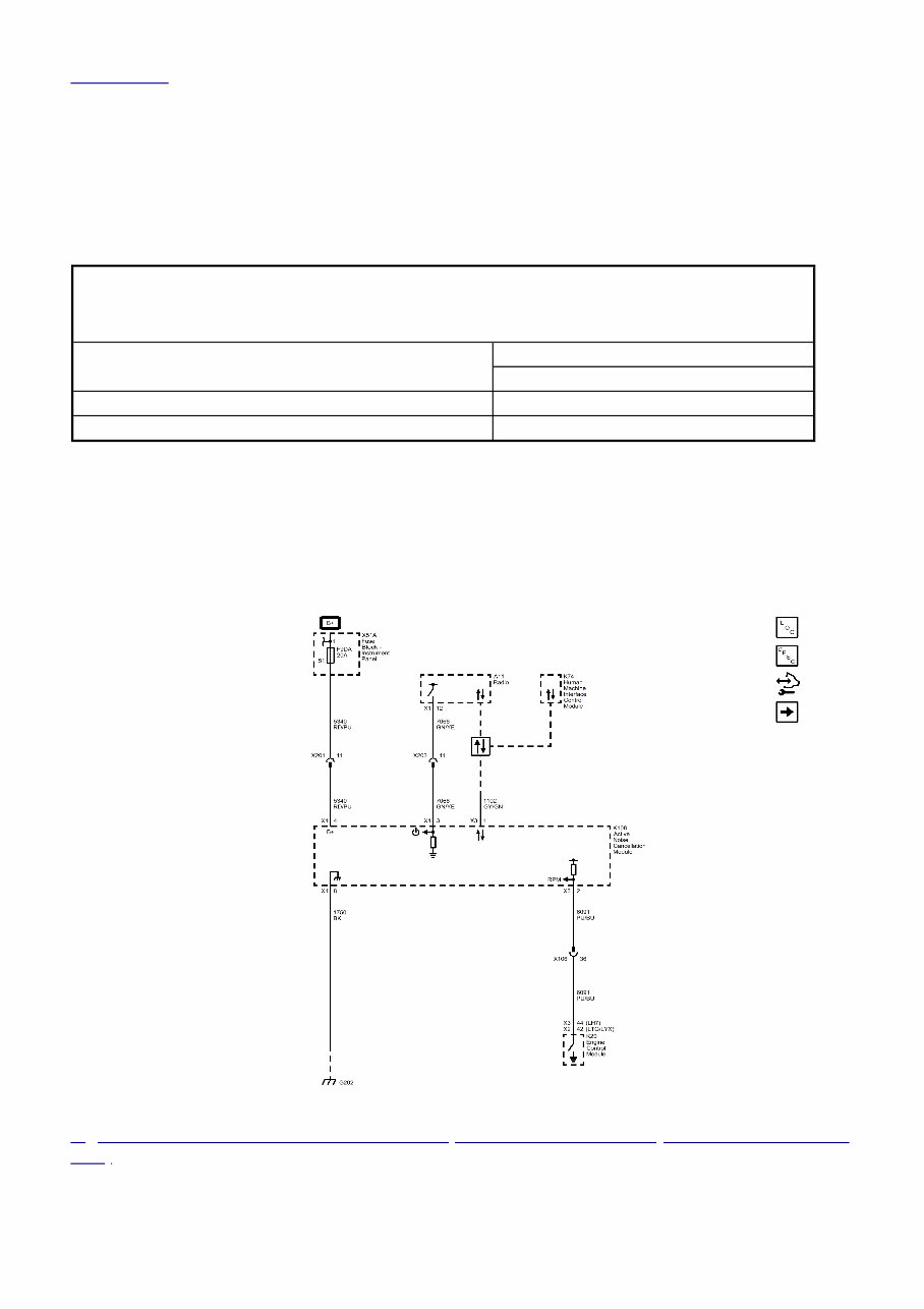
/ Back To Article 2018 ACCESSORIES & EQUIPMENT Active Noise Cancellation - Equinox & Terrain SPECIFICATIONS FASTENER SPECIFICATIONS Reusable Threaded Fastener Tightening Specifications NOTE: All fasteners listed in this table can be reused after removal. Application Specification Metric (English) Radio Speaker Amplifier Bolt 2.5 N.m (22 lb in) Radio Speaker Amplifier Nut 6 N.m (53 lb in) SCHEMATIC WIRING DIAGRAMS ACTIVE NOISE CANCELLATION WIRING SCHEMATICS Active Noise Cancellation Module Power, Ground and Serial Data (NKC with UZ6 without IOR) Fig. 1: Active Noise Cancellation Module Power, Ground and Serial Data (NKC with UZ6 without IOR) Courtesy of GENERAL MOTORS COMPANY Active Noise Cancellation Microphones (NKC with UZ6 without IOR)
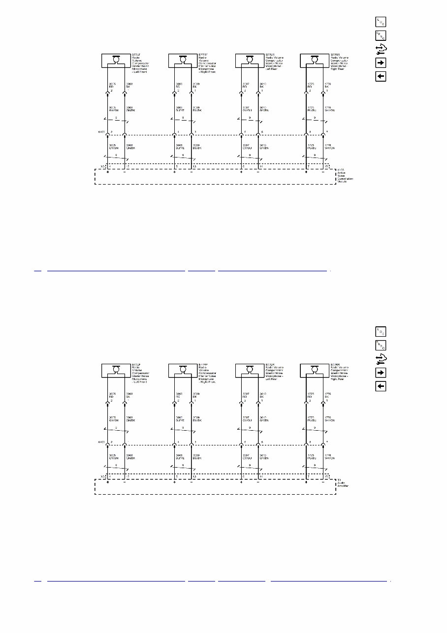
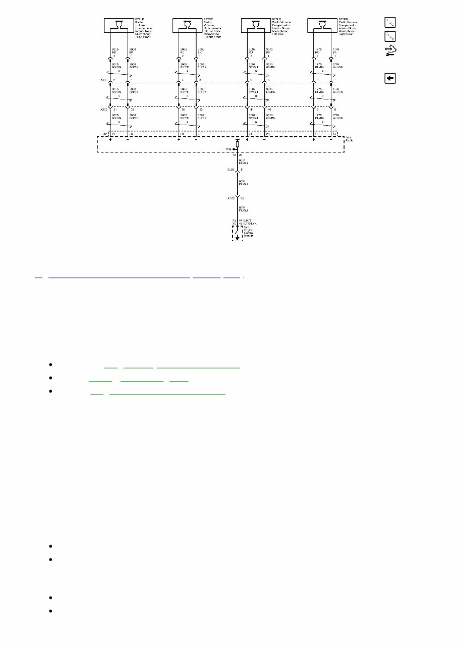
/ Fig. 2: Active Noise Cancellation Microphones (NKC with UZ6 without IOR) Courtesy of GENERAL MOTORS COMPANY Active Noise Cancellation Microphones (NKC and UQA with IO5/IO6/IOS/IOT/IOU) Fig. 3: Active Noise Cancellation Microphones (NKC and UQA with IO5/IO6/IOS/IOT/IOU) Courtesy of GENERAL MOTORS COMPANY Active Noise Cancellation Microphones (IOR)
/ Fig. 4: Active Noise Cancellation Microphones (IOR) Courtesy of GENERAL MOTORS COMPANY DIAGNOSTIC INFORMATION AND PROCEDURES DTC B0560: ENGINE RPM INPUT CIRCUIT SIGNAL INVALID Diagnostic Instructions Perform the Diagnostic System Check - Vehicle prior to using this diagnostic procedure. Review Strategy Based Diagnosis for an overview of the diagnostic approach. Refer to Diagnostic Procedure Instructions to provide an overview of each diagnostic category. DTC Descriptor DTC B0560 08 Engine RPM Input Circuit Signal Invalid Circuit/System Description The Audio Amplifier receives a discrete pulse-width modulated engine speed signal from the Engine Control Module. The Audio Amplifier uses the engine RPM signal for operating active noise cancellation. Conditions for Running the DTC Engine running, Radio ON Battery voltage between 9 - 16 volts. Conditions for Setting the DTC The Audio Amplifier receives a serial data message that the engine is running. The discrete engine speed signal to the Audio Amplifier indicates the engine speed is less than 300 RPM or greater than 9000 RPM. Action Taken When the DTC Sets
/ The active noise cancellation system is disabled. Conditions for Clearing the DTC A current DTC clears when a valid engine speed signal between 300 - 9000 RPM is received. A history DTC clears when the ignition cycle counter reaches the reset threshold without a repeat of the malfunction. Reference Information Schematic Reference Active Noise Cancellation Wiring Schematics Connector End View Reference COMPONENT CONNECTOR END VIEWS - INDEX Description and Operation Active Noise Cancellation Description and Operation Electrical Information Reference Circuit Testing Connector Repairs Testing for Intermittent Conditions and Poor Connections Wiring Repairs Scan Tool Reference Control Module References for scan tool information Circuit/System Testing NOTE: Diagnose any Engine Control Module DTCs before performing this diagnostic. 1. Ignition OFF, disconnect the X3 harness connector at the T3 Audio Amplifier. 2. Engine running at 600 RPM, 3. Test for 575-800 Hz AC between the signal circuit terminal 2 and ground. If not between 575-800 Hz AC 1. Ignition OFF, disconnect the harness connector at the K20 Engine Control Module. Ignition ON. 2. Test for less than 1 V between the signal circuit and ground. If 1 V or greater, repair the short to voltage on the circuit. If less than 1 V 3. Ignition OFF. 4. Test for infinite resistance between the signal circuit and ground. If less than infinite resistance, repair the short to ground on the circuit. If infinite resistance 5. Test for less than 2 Ω in the signal circuit end to end. If 2 Ω or greater, repair the open/high resistance in the circuit. If less than 2 Ω, replace the K20 Engine Control Module. Go to next step: If between 575-800 Hz AC 4. Test or replace the T3 Audio Amplifier. Repair Instructions
/ Perform the Diagnostic Repair Verification after completing the repair. Refer to Control Module References for Audio Amplifier or Engine Control Module replacement, programming, and setup. DTC B126E, B126F, B127C, OR B127D: MICROPHONE (2-5) INPUT SIGNAL CIRCUIT (IOR) Diagnostic Instructions Perform the Diagnostic System Check - Vehicle prior to using this diagnostic procedure. Review Strategy Based Diagnosis for an overview of the diagnostic approach. Refer to Diagnostic Procedure Instructions to provide an overview of each diagnostic category. DTC Descriptors DTC B127C Microphone 2 Input Signal Circuit DTC B127D Microphone 3 Input Signal Circuit DTC B126F Microphone 4 Input Signal Circuit DTC B126E Microphone 5 Input Signal Circuit For symptom byte information refer to Symptom Byte List Diagnostic Fault Information Circuit Short to Ground Open/High Resistance Short to Voltage Signal Performance Microphone High Signal Circuit (LF) B127C 02 B127C 04 B127C 01 B127C 1A Microphone Low Signal Circuit (LF) B127C 02 B127C 04 B127C 01 B127C 1A Microphone High Signal Circuit (RF) B127D 02 B127D 04 B127D 01 B127D 1A Microphone Low Signal Circuit (RF) B127D 02 B127D 04 B127D 01 B127D 1A Microphone High Signal Circuit (LR) B126F 02 B126F 04 B126F 01 B126F 1A Microphone High Signal Circuit (LR) B126F 02 B126F 04 B126F 01 B126F 1A Microphone Low Signal Circuit (RR) B126E 02 B126E 04 B126E 01 B126E 1A Microphone Low Signal Circuit (RR) B126E 02 B126E 04 B126E 01 B126E 1A Circuit/System Description The active noise cancellation system uses four microphones in the vehicle headliner: one above each front seating position, and two above the rear seats. The Radio provides a bias voltage to each microphone (+) and (-) signal circuits for operation of the microphone. The microphones monitor the vehicle cabin for undesirable engine sounds. The Audio Amplifier uses the microphone inputs and an engine RPM signal to determine the frequency of the undesirable sound.
/ Conditions for Running the DTC The Radio performs a self diagnostic of the microphone circuits 16 seconds after initial power up, then periodically every 400 milliseconds thereafter. Conditions for Setting the DTC DTC B127C 01, B127D 01, B126F 01, B126E 01 DTC B1325 is not current A short to voltage is detected on the specified (+) or (-) signal circuit for more than 1.5 seconds DTC B127C 02, B127D 02, B126F 02, B126E 02 DTC B1325 is not current A short to ground is detected on the specified (+) or (-) signal circuit for more than 1.5 seconds DTC B127C 04, B127D 04, B126F 04, B126E 04 DTC B1325 is not current An open is detected on the specified (+) or (-) signal circuit for more than 1.5 seconds DTC B127C 1A, B127D 1A, B126F 1A, B126E 1A DTC B1325 is not current An out of range voltage is detected on the specified (+) or (-) signal circuit for more than 1.5 seconds Action Taken When the DTC Sets The active noise cancellation system is disabled. Conditions for Clearing the DTC A current DTC clears when the self diagnostic passes on the next ignition cycle. A history DTC clears when the ignition cycle counter reaches the reset threshold without a repeat of the malfunction. Diagnostic Aids Installation of aftermarket replacement speakers, additional speakers/subwoofers, or aftermarket exhaust systems can cause undesirable behavior of the active noise cancellation system. The noise reduction microphones have foam blocks above them to seal the microphones and aid in the reduction of headliner vibration. Missing or out of place foam blocks can impact system performance. Reference Information Schematic Reference Active Noise Cancellation Wiring Schematics Connector End View Reference COMPONENT CONNECTOR END VIEWS - INDEX Description and Operation Active Noise Cancellation Description and Operation Electrical Information Reference Circuit Testing
/ Connector Repairs Testing for Intermittent Conditions and Poor Connections Wiring Repairs Scan Tool Reference Control Module References for scan tool information Circuit/System Testing 1. Ignition OFF, disconnect the harness connector at the appropriate B77 Radio Volume Compensator Interior Noise Microphone. Ignition ON. 2. Test for 8.5 - 9.5 V between the signal circuit terminal 2 and ground. If less than 8.5 V 1. Ignition OFF, disconnect the X2 harness connector at the A11 Radio. 2. Test for infinite resistance between the signal circuit and ground. If less than infinite resistance, repair the short to ground in the circuit. If infinite resistance 3. Test for less than 2 Ω in the signal circuit end to end. If 2 Ω or greater, repair the open/high resistance in the circuit. If less than 2 Ω, replace the A11 Radio. If greater than 9.5 V 1. Ignition OFF, disconnect the X2 harness connector at the A11 Radio. Ignition ON. 2. Test for less than 1 V between the signal circuit and ground. If 1 V or greater, repair the short to voltage on the circuit. If less than 1 V, replace the A11 Radio. Go to next step: If between 8.5 - 9.5 V 3. Test for less than 1 V between the signal circuit terminal 1 and ground. If greater than 1 V 1. Ignition OFF, disconnect the X2 harness connector at the A11 Radio. Ignition ON. 2. Test for less than 1 V between the signal circuit and ground. If 1 V or greater, repair the short to voltage in the circuit. If less than 1 V, replace the A11 Radio. Go to next step: If less than 1 V 4. Ignition OFF, disconnect the X2 harness connector at the A11 Radio. 5. Test for infinite resistance between the appropriate B77 Radio Volume Compensator Interior Noise Microphone signal circuit terminal 1 and ground. If less than infinite resistance Repair the short to ground in the circuit Go to next step: If infinite resistance 6. Test for less than 2 Ω in the signal circuit end to end. If 2 Ω or greater Repair the open/high resistance in the circuit Go to next step: If less than 2 Ω 7. Replace the appropriate B77 Radio Volume Compensator Interior Noise Microphone. 8. Ignition ON 9. Verify the DTC does NOT set. If the DTC sets Replace the A11 Radio.
/ Go to next step: If the DTC does not set 10. All OK. Repair Instructions Perform the Diagnostic Repair Verification after completing the repair. Refer to Active Noise Cancellation Microphone Replacement Refer to Control Module References for Audio Amplifier replacement, programming, and setup. DTC B1277, B127C, B127D, OR B126F: MICROPHONE (1-4) INPUT SIGNAL CIRCUIT (WITHOUT IOR) Diagnostic Instructions Perform the Diagnostic System Check - Vehicle prior to using this diagnostic procedure. Review Strategy Based Diagnosis for an overview of the diagnostic approach. Refer to Diagnostic Procedure Instructions to provide an overview of each diagnostic category. DTC Descriptors DTC B1277 Microphone 1 Input Signal Circuit DTC B127C Microphone 2 Input Signal Circuit DTC B127D Microphone 3 Input Signal Circuit DTC B126F Microphone 4 Input Signal Circuit For symptom byte information refer to Symptom Byte List Diagnostic Fault Information Circuit Short to Ground Open/High Resistance Short to Voltage Signal Performance Microphone High Signal Circuit (LF) B1277 02 B1277 04 B1277 01 B1277 1A Microphone Low Signal Circuit (LF) B1277 02 B1277 04 B1277 01 B1277 1A Microphone High Signal Circuit (RF) B127C 02 B127C 04 B127C 01 B127C 1A Microphone Low Signal Circuit (RF) B127C 02 B127C 04 B127C 01 B127C 1A Microphone High Signal Circuit (LR) B127D 02 B127D 04 B127D 01 B127D 1A Microphone High Signal Circuit (LR) B127D 02 B127D 04 B127D 01 B127D 1A Microphone Low Signal Circuit (RR) B126F 02 B126F 04 B126F 01 B126F 1A Microphone Low Signal Circuit (RR) B126F 02 B126F 04 B126F 01 B126F 1A Circuit/System Description
/ The active noise cancellation system uses four microphones in the vehicle headliner: one above each front seating position, and two above the rear seats. The Audio Amplifier/Active Noise Cancellation Module provides a bias voltage to each microphone (+) and (-) signal circuits for operation of the microphone. The microphones monitor the vehicle cabin for undesirable engine sounds. The Audio Amplifier uses the microphone inputs and an engine RPM signal to determine the frequency of the undesirable sound. Conditions for Running the DTC The Audio Amplifier/Active Noise Cancellation Module performs a self diagnostic of the microphone circuits 16 seconds after initial power up, then periodically every 400 milliseconds thereafter. Conditions for Setting the DTC DTC B1277 01, B127C 01, B127D 01, B126F 01 DTC B1325 is not current A short to voltage is detected on the specified (+) or (-) signal circuit for more than 1.5 seconds DTC B1277 02, B127C 02, B127D 02, B126F 02 DTC B1325 is not current A short to ground is detected on the specified (+) or (-) signal circuit for more than 1.5 seconds DTC B1277 04, B127C 04, B127D 04, B126F 04 DTC B1325 is not current An open is detected on the specified (+) or (-) signal circuit for more than 1.5 seconds DTC B1277 1A, B127C 1A, B127D 1A, B126F 1A DTC B1325 is not current An out of range voltage is detected on the specified (+) or (-) signal circuit for more than 1.5 seconds Action Taken When the DTC Sets The active noise cancellation system is disabled. Conditions for Clearing the DTC A current DTC clears when the self diagnostic passes on the next ignition cycle. A history DTC clears when the ignition cycle counter reaches the reset threshold without a repeat of the malfunction. Diagnostic Aids Installation of aftermarket replacement speakers, additional speakers/subwoofers, or aftermarket exhaust systems can cause undesirable behavior of the active noise cancellation system. The noise reduction microphones have foam blocks above them to seal the microphones and aid in the reduction of headliner vibration. Missing or out of place foam blocks can impact system performance. Reference Information Schematic Reference Active Noise Cancellation Wiring Schematics Connector End View Reference COMPONENT CONNECTOR END VIEWS - INDEX
2018-2020 Chevrolet Equinox Service & Repair Manual
The 2018-2020 Chevrolet Equinox Service & Repair Manual is an essential guide for maintaining and repairing your Chevrolet Equinox. Developed by Chevrolet, this manual provides comprehensive instructions and precise specifications for accurate maintenance and effective troubleshooting.
Inside, you'll find step-by-step procedures for routine maintenance tasks such as oil changes, brake inspections, and tire rotations. The manual also covers more complex repairs, including engine diagnostics, transmission servicing, and electrical system troubleshooting. Detailed diagrams and illustrations assist in identifying components and ensure repairs are conducted correctly and efficiently.
This manual is designed for professional technicians and experienced DIY enthusiasts alike. It delivers the critical technical information needed to keep your 2018-2020 Chevrolet Equinox running smoothly. By adhering to the detailed guidance provided, you can ensure long-term reliability and optimal performance, maximizing the operational lifespan of your vehicle.
Printable: Yes Language: English Compatibility: Pretty much any electronic device, incl. PC & Mac computers, Android and Apple smartphones & tablet, etc. Requirements: Adobe Reader (free)
Recently Viewed
5,521,897Happy Clients
2,594,462eManuals
1,120,453Trusted Sellers
15Years in Business
Price:
Actual Price:
2018-2020 Chevrolet Equinox Service & Repair Manual