

1983-1994 Chevrolet Corvette C4 Service & Repair Manual
What's Included?
Fast Download Speeds
Online & Offline Access
Access PDF Contents & Bookmarks
Full Search Facility
Print one or all pages of your manual

1984-1996 CHEVROLET
CORVETTE SERVICE AND
REPAIR MANUAL
1989-90 ENGINES
5.0L & 5.7L TPI V8 - VINS F & 8
ENGINE IDENTIFICATION
The engine may be identified from the Vehicle Identification Number (VIN). The VIN is stamped on a plate, on
top of instrument panel and visible through the windshield. The VIN contains 17 characters. The 8th character
of the VIN identifies the engine.
The 10th character of the VIN identifies the model year (K = 1989, L = 1990). All engines are stamped with an
engine identification label. This engine identification label will identify the assembly plant, month/date
produced and the engine type code.
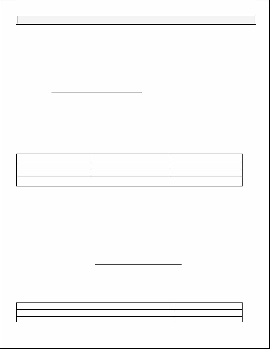
ENGINE IDENTIFICATION CODES
ADJUSTMENTS
VALVE ARRANGEMENT
Valve Arrangement
E-I-I-E-E-I-I-E (Front-to-rear, both banks).
VALVE CLEARANCE ADJUSTMENT
1. Place number one cylinder on TDC of compression stroke. Ensure timing mark on damper and front
cover are aligned. Refer to the VALVE ADJUSTMENT SEQUENCE table below. Back off adjusting
nut until lash is felt at pushrod. Rotate pushrod while tightening adjusting nut until lash is removed. With
lash removed, tighten adjusting nut 3/4 to 1 1/4 additional turn.
2. Rotate crankshaft one revolution and align timing marks. No. 6 cylinder will be on TDC. Adjust
remaining valves in same manner.
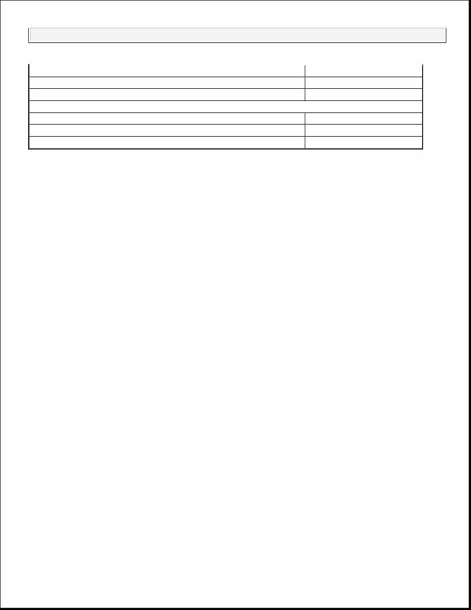
VALVE ADJUSTMENT SEQUENCE
NOTE: Unless stated otherwise, references to Camaro and Firebird apply to 5.0L and
5.7L engines. For engine repair procedures not covered in this article, see
ENGINE OVERHAUL PROCEDURES article in GENERAL INFORMATION.
Application
(1)
Engine Code VIN Code
5.0L TPI LB9 F
5.7L TPI L98 8
(1)
Unless stated otherwise, references to Camaro and Firebird apply to 5.0L and 5.7L engines.
Cylinder No. Valve
No. One Cylinder On TDC
1989-90 ENGINES 5.0L & 5.7L TPI V8 - VINS F & 8 1989-90 ENGINES 5.0L & 5.7L TPI V8 - VINS F & 8
TROUBLE SHOOTING
REMOVAL & INSTALLATION
GENERAL PRECAUTION
FUEL PRESSURE RELEASE
Before servicing any fuel related component on fuel injected models, fuel pressure must be released. Loosen
fuel tank filler cap. Connect Fuel Gauge (J 34730-1) to fuel pressure connection mounted on fuel rail, right side
of fuel pressure regulator. Wrap shop towel around fitting during installation to avoid spillage. Install bleed
hose. Turn gauge valve and drain fuel into a proper container.
RADIATOR UPPER SUPPORT
No. 1 Intake & Exhaust
No. 2, 5 & 7 Intake
No. 3, 4 & 8 Exhaust
No. 6 Cylinder On TDC
No. 6 Intake & Exhaust
No. 2, 5 & 7 Exhaust
No. 3, 4 & 8 Intake
NOTE: See TROUBLE SHOOTING - BASIC PROCEDURES article in the GENERAL
TROUBLE SHOOTING section.
NOTE: For reassembly reference, label all electrical connectors, vacuum hoses and
fuel lines prior to removal. Match mark engine hood and all other major
components prior to removal.
1989-90 ENGINES 5.0L & 5.7L TPI V8 - VINS F & 8
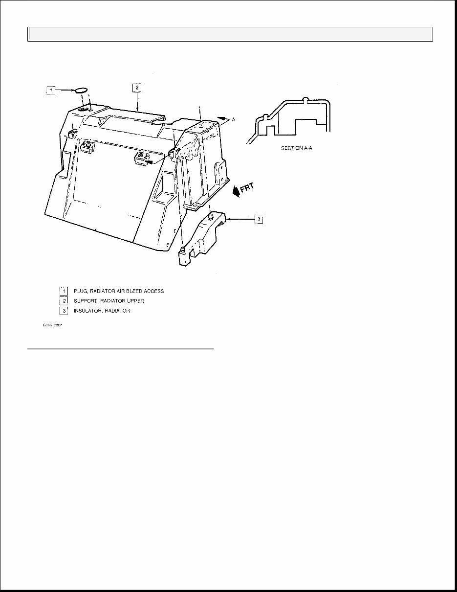
Fig. 1: View Of Radiator Upper Support (1 Of 2)
1989-90 ENGINES 5.0L & 5.7L TPI V8 - VINS F & 8
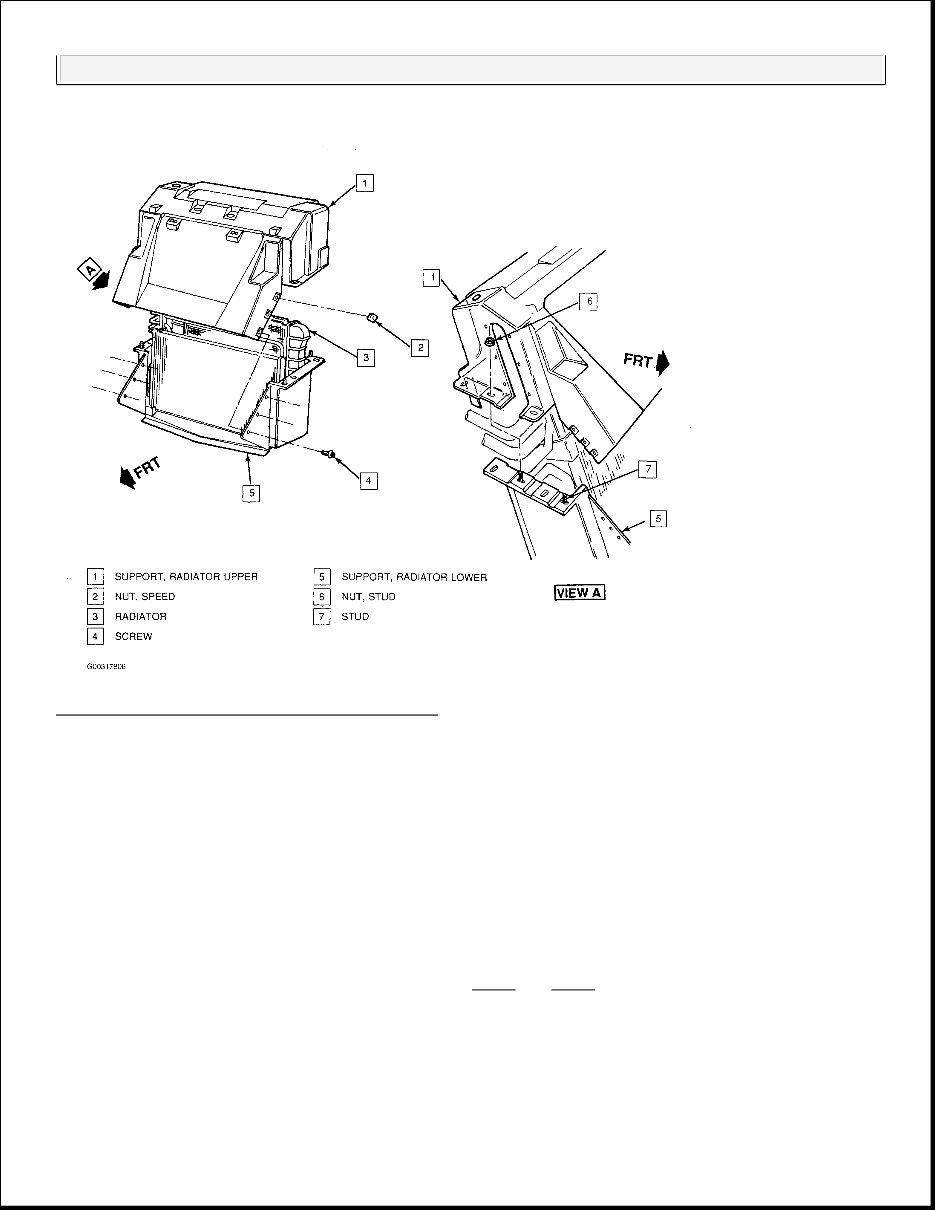
Fig. 2: View Of Radiator Upper Support (2 Of 2)
L98
Removal
1. Battery negative cable.
2. Pressure cap.
3. Drain coolant.
4. Air Cleaner assembly.
5. Electrical connectors from cooling fan relays.
6. Bolts retaining accumulator bracket to radiator upper support.
7. Screws retaining fan shroud to upper support. See Fig. 1 and Fig. 2 .
8. Rubber access plug from top of radiator.
9. Radiator air bleed hose clamp and hose.
10. Nuts and bolts retaining upper support to front side member.
11. Screws retaining upper support to lower support.
1989-90 ENGINES 5.0L & 5.7L TPI V8 - VINS F & 8

12. Upper support from vehicle.
Installation
1. Upper support.
2. Screws retaining upper support to lower support.
3. Nuts and bolts retaining upper support to front side member. See Fig. 1 and Fig. 2 .
4. Electrical connectors to cooling fan relays.
5. Screws retaining fan shroud to upper support.
6. Bolts retaining accumulator bracket to radiator upper support.
7. Radiator air bleed hose clamp and hose.
8. Access plug.
9. Air Cleaner assembly.
10. Refill coolant.
11. Battery negative cable.
12. Pressure cap.
LT5
Removal
1. Battery negative cable.
2. Pressure cap.
3. Drain coolant.
4. Air Cleaner assembly.
5. Radiator upper air deflector.
6. Electrical connectors from cooling fan relays.
7. Bolts retaining accumulator bracket to radiator upper support. See Fig. 1 and Fig. 2 .
8. Screws retaining fan shroud to upper support.
9. Rubber access plug from top of radiator.
10. Radiator air bleed hose clamp and hose.
11. Nuts and bolts retaining upper support to front side member.
12. Bolt retaining oil cooler lines to oil cooler.
13. Seal retainers and seal from oil cooler and A/C line.
14. AIR pump.
15. Bolt retaining AIR pump bracket at rear; loosen front bolt.
16. Air pump intake duct.
IMPORTANT: Tighten: Upper support to front side member nuts and bolts to 25 N.m (18
Ft. lbs)
1989-90 ENGINES 5.0L & 5.7L TPI V8 - VINS F & 8

17. Screws retaining upper support to lower support.
18. Upper support from vehicle.
Installation
1. Upper support.
2. Screws retaining upper support to lower support.
3. Nuts and bolts retaining upper support to front side member. See Fig. 1 and Fig. 2 .
4. Air pump intake duct.
5. Bolt retaining AIR pump bracket
6. AIR pump.
7. Electrical connectors to cooling fan relays.
8. Screws retaining fan shroud to upper support.
9. Bolts retaining accumulator bracket to radiator upper support.
10. Retainers to oil cooler /A/C line seal.
11. Bolt retaining oil cooler lines to oil cooler.
12. Air bleed hose and clamp.
13. Access plug.
14. Radiator upper air deflector.
15. Air Cleaner assembly.
16. Refill coolant.
17. Battery negative cable.
18. Pressure cap.
RADIATOR
IMPORTANT: Tighten: Upper support to front side member nuts and bolts to 25 N.m (18
Ft. Lbs.)
IMPORTANT: Tighten: Fan shroud screws to 9 N.m (80 Inch Lbs.)
IMPORTANT: Tighten: Accumulator bracket bolts to 9 N.m (80 Inch Lbs.)
IMPORTANT: Tighten: Oil cooler line bolt to 10 N.m (89 Inch Lbs.)
1989-90 ENGINES 5.0L & 5.7L TPI V8 - VINS F & 8
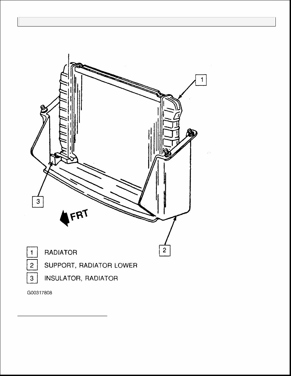
Fig. 3: Removing Radiator Assembly
L98
Removal
1989-90 ENGINES 5.0L & 5.7L TPI V8 - VINS F & 8

1. Radiator upper support. See Radiator Upper Support L98 .
2. Radiator inlet and outlet clamps and hoses.
3. Automatic transmission oil cooler lines from radiator (if equipped).
4. Radiator from vehicle. See Fig. 3 .
Installation
1. Radiator. See Fig. 3 .
2. Automatic transmission oil cooler lines to radiator (if equipped).
3. Radiator inlet and outlet clamps and hoses.
4. Radiator upper support.
LT5
Removal
1. Radiator upper support. See Radiator Upper Support LT5 .
2. Radiator inlet and outlet clamps and hoses.
3. Radiator from vehicle.
Installation
1. Radiator.
2. Radiator inlet and outlet clamps and hoses.
3. Radiator upper support.
INTAKE MANIFOLD
Removal
1. Disconnect negative battery cable and drain cooling system. Relieve fuel pressure. See FUEL
PRESSURE RELEASE . Remove air intake duct assembly. Disconnect accelerator, throttle valve and
cruise control cables (if equipped). Mark and disconnect necessary electrical connectors and vacuum
hoses.
2. Remove bolts attaching left runners to upper and lower intake manifold. See Fig. 4 . Remove PCV valve
and hose. Remove bolts attaching right runners to upper and lower intake manifold. Remove EGR
solenoid.
3. Remove bolts retaining lower manifold to runners on each side. Right side bolt is located near engine
front and left side bolt is located near rear of engine. Remove upper intake manifold and runners. Remove
and discard gaskets.
4. Disconnect injector harness and fuel lines. Remove fuel rail and injectors as an assembly. Mark and
IMPORTANT: Tighten Fittings to 27 N.m (20 Ft. Lbs.)
1989-90 ENGINES 5.0L & 5.7L TPI V8 - VINS F & 8

remove spark plug wires at distributor. Mark position of distributor for installation reference and remove
distributor assembly. Disconnect necessary cooling system hoses. Remove lower intake manifold bolts.
Remove lower intake manifold and gaskets.
Installation
1. Clean all gasket surfaces. Apply 3/16" bead of RTV Sealer (1052289) on front and rear of cylinder block
and up 1/2" onto each cylinder head. Install NEW gaskets. Install lower intake manifold.
2. Apply Thread Sealant (1052624) to lower intake manifold bolts. Tighten bolts and studs in sequence to
specifications. See TORQUE SPECIFICATIONS . See Fig. 4 . To complete installation, reverse removal
procedure.
1989-90 ENGINES 5.0L & 5.7L TPI V8 - VINS F & 8
You're Reading a Preview
What's Included?
Fast Download Speeds
Online & Offline Access
Access PDF Contents & Bookmarks
Full Search Facility
Print one or all pages of your manual
$41.99
Viewed 97 Times Today


Secure transaction
What's Included?
Fast Download Speeds
Online & Offline Access
Access PDF Contents & Bookmarks
Full Search Facility
Print one or all pages of your manual
$41.99
Get your hands on the 1983-1996 Chevrolet Corvette C4 Service & Repair Manual, a comprehensive guide ideal for both professional mechanics and DIY enthusiasts. This manual covers every service and repair procedure specific to the Chevrolet Corvette C4 for the model years 1983-1996 with clear, step-by-step instructions and detailed pictures.
The manual provides:
- Easy-to-follow service and repair procedures, allowing you to perform repairs and potentially save on professional costs
- Downloadable content that you keep forever, with printable pages, chapters, or the entire manual
- Compatibility with PCs, MACs, tablets, and smartphones, requiring only Adobe Reader (commonly pre-installed or available for free download)
All relevant models, engines, trim, and transmission types for the Chevrolet Corvette C4 are covered, ensuring detailed technical information from A-Z for every service need.
After payment via Visa, MasterCard, or PayPal, the manual is instantly emailed to the address provided during checkout, guaranteeing fast access and full customer satisfaction.


