ACCESSORIES & EQUIPMENT Cellular, Entertainment, and Navigation - Caprice SPECIFICATIONS FASTENER TIGHTENING SPECIFICATIONS Fastener Tightening Specifications SCHEMATIC WIRING DIAGRAMS RADIO/NAVIGATION SYSTEM WIRING SCHEMATICS Radio Power, Ground, and Serial Data Wiring Schematics Application Specification Metric English Amplifier Mounting Bracket to Vehicle Retaining Bolts 22 N.m 16 lb ft Amplifier to Battery Tray 15 N.m 11 lb in Amplifier to Mounting Bracket Retaining Screws 2 N.m 18 lb in Radio Antenna Module Ground Point to Roof Panel Retaining Bolt 2 N.m 18 lb in Radio Antenna Module to Roof Panel Retaining Bolt 4 N.m 35 lb in Radio Front Side Door Lower Speaker Screws 2 N.m 18 lb in Radio Front Speaker Screws 2 N.m 18 lb in Radio Rear Side Door Speaker Screws 2 N.m 18 lb in Radio Rear Speaker Screws 2 N.m 18 lb in Radio Screws 2 N.m 18 lb in
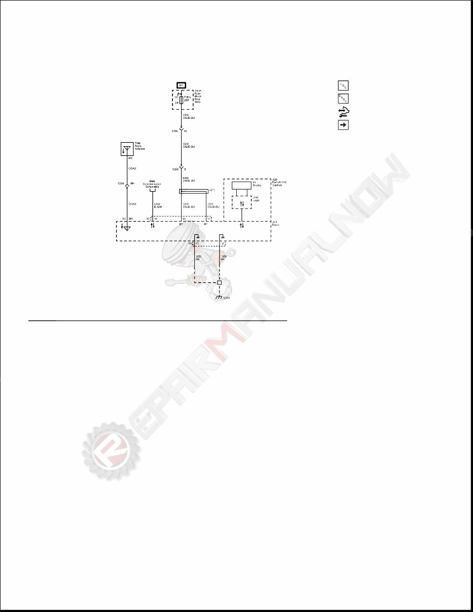
Fig. 1: Radio Power, Ground, and Serial Data Wiring Schematics Courtesy of GENERAL MOTORS COMPANY Speakers (without WX7) Wiring Schematics
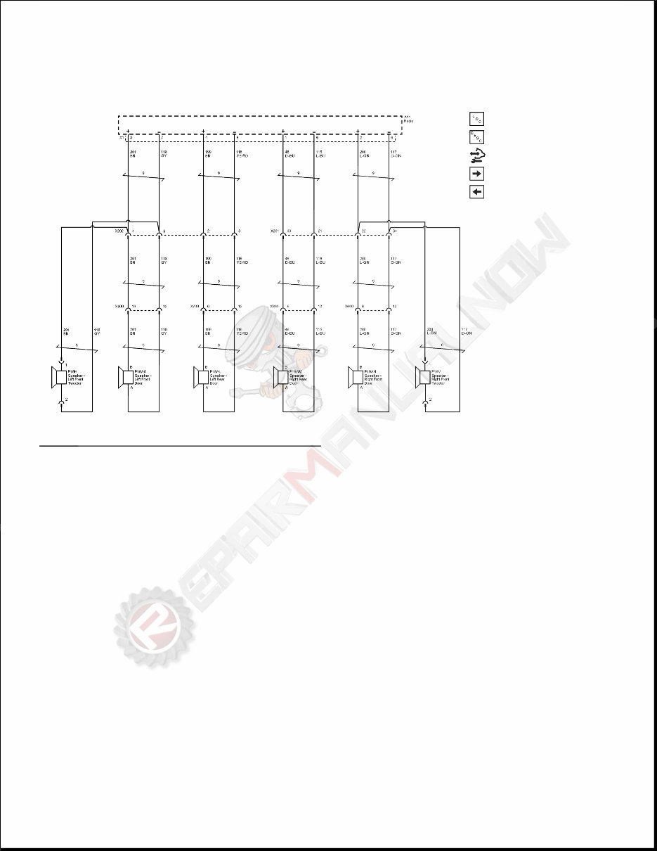
Fig. 2: Speakers (without WX7) Wiring Schematics Courtesy of GENERAL MOTORS COMPANY Speakers (WX7) Wiring Schematics
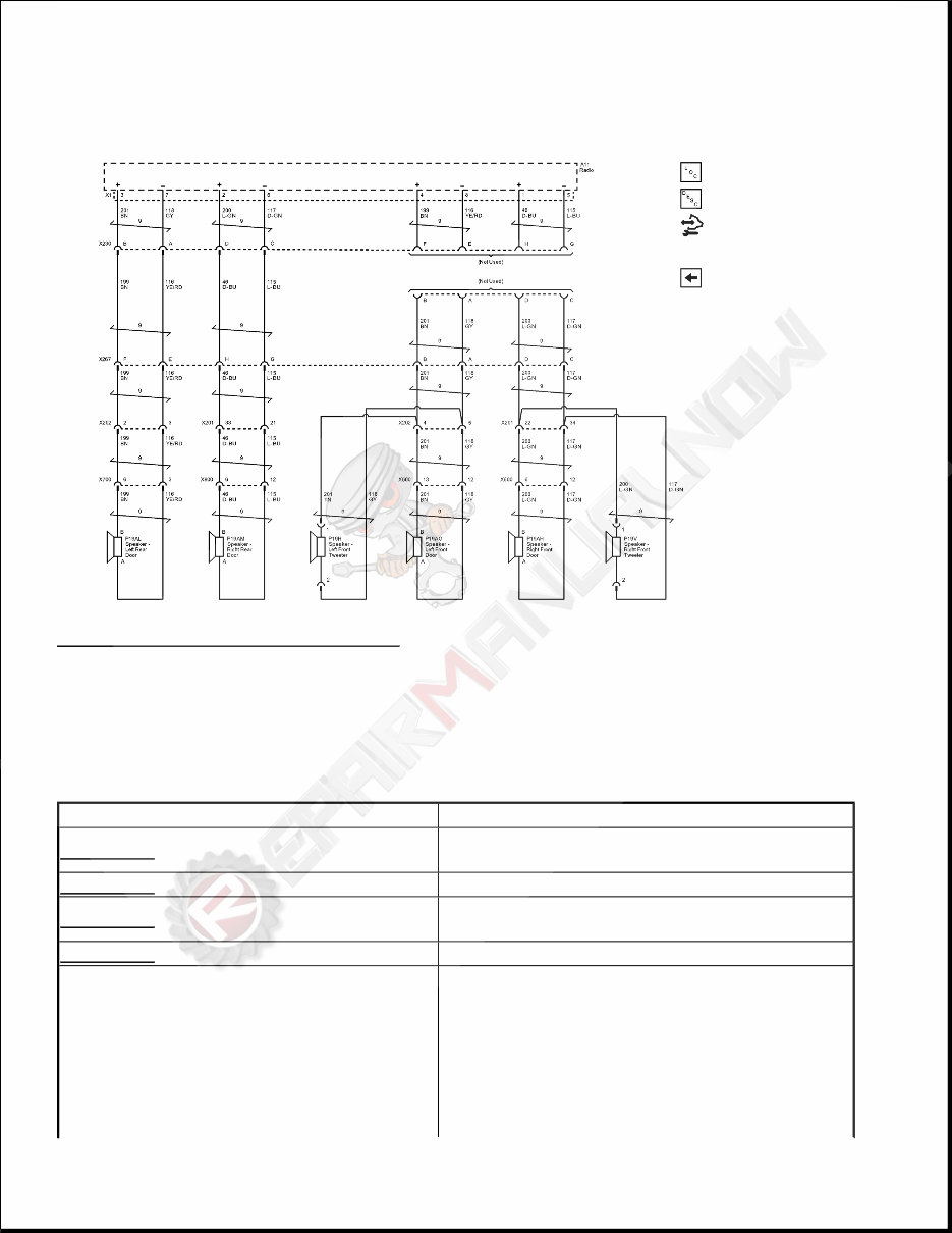
Fig. 3: Speakers (WX7) Wiring Schematics Courtesy of GENERAL MOTORS COMPANY DIAGNOSTIC INFORMATION AND PROCEDURES DIAGNOSTIC CODE INDEX DIAGNOSTIC CODE INDEX DTC Description DTC B0997 DTC B0997 3A Auxiliary Electronic Control Unit (ECU) 2 Performance Incorrect Component DTC B1019 DTC B1019 45 System Configuration Error DTC B1020 DTC B1020 39: Auxiliary Electronic Unit (ECU) Performance Internal Electronic Failure DTC B1023 DTC B1023 00 Integral Switch Performance DTC B1025 01 Audio Output 1 Left Front Circuit Short to Battery DTC B1025 02 Audio Output 1 Left Front Circuit Short to Ground DTC B1025 04 Audio Output 1 Left Front Circuit Open DTC B1025 0E Audio Output 1 Left Front Circuit Resistance below Threshold
DTC B0997 Diagnostic Instructions Perform the Diagnostic System Check - Vehicle prior to using this diagnostic procedure. Review Strategy Based Diagnosis for an overview of the diagnostic approach. Diagnostic Procedure Instructions provides an overview of each diagnostic category. DTC Descriptor DTC B0997 3A Auxiliary Electronic Control Unit (ECU) 2 Performance Incorrect Component Circuit/System Description The EEPROM (Electrically Erasable Programmable Read Only Memory) is part of the printed circuit board housed within the radio/HVAC control assembly. It stores the variables required for the operation of the DTC B1025, B1035, B1045, or B1055 DTC B1035 01 Audio Output 2 Right Front Circuit Short to Battery DTC B1035 02 Audio Output 2 Right Front Circuit Short to Ground DTC B1035 04 Audio Output 2 Right Front Circuit Open DTC B1035 0E Audio Output 2 Right Front Circuit Resistance below Threshold DTC B1045 01 Audio Output 3 Left Rear Circuit Short to Battery DTC B1045 02 Audio Output 3 Left Rear Circuit Short to Ground DTC B1045 04 Audio Output 3 Left Rear Circuit Open DTC B1045 0E Audio Output 3 Left Rear Circuit Resistance below Threshold DTC B1055 01 Audio Output 4 Right Rear Circuit Short to Battery DTC B1055 02 Audio Output 4 Right Rear Circuit Short to Ground DTC B1055 04 Audio Output 4 Right Rear Circuit Open DTC B1055 0E Audio Output 4 Right Rear Circuit Resistance below Threshold DTC B1240 DTC B1240 00 Compact Disc Player Not Responding DTC B125A DTC B125A 02 Antenna 1 Circuit Short to Ground DTC B125A 04 Antenna 1 Circuit Open DTC B1271 DTC B1271 00 Theft Protection Active
entertainment system. Conditions for Running DTC Ignition is ON or in the ACC position The system voltage is 9-16 V The test is run once during radio wake up Conditions for Setting the DTC The radio display internal EEPROM has failed or is corrupt. An incompatible radio/HVAC control assembly is installed to the radio. Action Taken When DTC Sets The radio will set the DTC and the infotainment system will not function. Conditions for Clearing the DTC The radio detects that a compatible radio/HVAC control assembly is installed to the radio. Reference Information Schematic Reference Radio/Navigation System Schematics Connector End View Reference COMPONENT CONNECTOR END VIEWS - INDEX Description and Operation Radio/Audio System Description and Operation Electrical Information Reference Circuit Testing Connector Repairs Testing for Intermittent Conditions and Poor Connections Wiring Repairs Scan Tool Reference Control Module References for scan tool information
Circuit/System Verification If this DTC is retrieved as a current DTC, replace the radio/HVAC control assembly. Repair Instructions Perform the Diagnostic Repair Verification after completing the diagnostic procedure. Radio Control Assembly Replacement DTC B1019 Diagnostic Instructions Perform the Diagnostic System Check - Vehicle prior to using this diagnostic procedure. Review Strategy Based Diagnosis for an overview of the diagnostic approach. Diagnostic Procedure Instructions provides an overview of each diagnostic category. DTC Descriptor DTC B1019 45 System Configuration Error Circuit/System Description When the ignition is turned ON, the radio performs a self test to verify proper calibration exists within the system. Conditions for Running the DTC This DTC test runs when the radio changes from OFF to ON. Conditions for Setting the DTC The radio calibration has failed or is corrupt. Action Taken When DTC Sets The system will set the DTC and disable itself. Conditions for Clearing the DTC Re-calibration with the correct calibrations for the vehicle and cycling the radio to OFF then to ON will clear the DTC if there is no damage to the radio. Reference Information
Schematic Reference Radio/Navigation System Schematics Connector End View Reference COMPONENT CONNECTOR END VIEWS - INDEX Description and Operation Radio/Audio System Description and Operation Electrical Information Reference Circuit Testing Connector Repairs Testing for Intermittent Conditions and Poor Connections Wiring Repairs Scan Tool Reference Control Module References for scan tool information Circuit/System Verification 1. Access the Service Programming System (SPS) and follow the on-screen instructions. 2. On the SPS Supported Controllers screen, select IRC Audio System - 3. Configuration & Setup and follow the on-screen instructions. 3. After completing the Configuration and Setup procedure, clear any DTCs and turn OFF the ignition. 4. Ignition ON, verify DTC B1019 is not set as current. If DTC B1019 is retrieved as a current DTC, replace the radio. Repair Instructions Perform the Diagnostic Repair Verification after completing the diagnostic procedure. Control Module References for radio replacement, setup, and programming DTC B1020 Diagnostic Instructions Perform the Diagnostic System Check - Vehicle prior to using this diagnostic procedure. Review Strategy Based Diagnosis for an overview of the diagnostic approach. Diagnostic Procedure Instructions provides an overview of each diagnostic category.
DTC Descriptor DTC B1020 39: Auxiliary Electronic Unit (ECU) Performance Internal Electronic Failure Circuit/System Description The radio communicates with the radio/HVAC control assembly via serial data. This DTC indicates a fault in the Bluetooth hardware in the radio/HVAC control assembly. No external circuits are involved. Conditions for Running the DTC Ignition is ON or in the ACC position The system voltage is 9-16 V The test is run once during radio wake up Conditions for Setting the DTC A message is received from the Bluetooth component that indicates initialization failure. Action Taken When the DTC Sets Bluetooth features will be inoperative An error message will be displayed if the phone or Bluetooth media are selected from the menu Conditions for Clearing the DTC A message is received from the Bluetooth component that indicates successful initialization during radio wake up. A history DTC clears after 50 fault-free ignition cycles. Diagnostic Aids This DTC may be stored as a history DTC without affecting the operation of the radio/HVAC control assembly. If stored only as a history DTC and not retrieved as a current DTC, do not replace the radio/HVAC control assembly. If this DTC is retrieved as both a current and history DTC, replace the radio/HVAC control assembly. Reference Information Schematic Reference Radio/Navigation System Schematics Connector End View Reference
The 2011 Chevrolet Caprice Service & Repair Manual is the perfect guide for maintaining and repairing this rear-wheel-drive sedan, known for its police-duty roots and solid drivetrains. Whether you're working with the 3.6L LY7 or LFX V6, or the 6.0L L77 V8, this manual provides detailed service procedures tailored to the platform—along with full coverage of the 6-speed 6L80 automatic transmission.
Inside, you'll find step-by-step instructions for engine servicing, transmission maintenance, cooling system checks, brake work, suspension inspections, and driveline repairs. Every task includes proper torque specs, clear mechanical tolerances, and procedures pulled straight from GM’s original service data.
This manual is made for those who want to keep their Caprice running strong—whether it’s daily-driven or repurposed for performance. It's written in a straightforward, shop-friendly tone that helps you work efficiently, without the guesswork. Perfect for both pro mechanics and capable DIYers who like doing things right.
Printable: Yes Language: English Compatibility: Pretty much any electronic device, incl. PC & Mac computers, Android and Apple smartphones & tablet, etc. Requirements: Adobe Reader (free)