1995 Chevrolet C1500 Service & Repair Manual Software
What's Included?
Lifetime Access
Fast Download Speeds
Online & Offline Access
Access PDF Contents & Bookmarks
Full Search Facility
Print one or all pages of your manual
CHEVROLET C/K SERVICE AND REPAIR MANUAL 1988-2002
A/C COMPRESSOR CLUTCH CONTROLS 1994 AIR CONDITIONING & HEAT General Motors Corp. A/C Compressor Clutch Controls MODEL IDENTIFICATION SERIES CODE DESIGNATIONS (LIGHT TRUCKS & VANS) DESCRIPTION & OPERATION On vehicles with a Powertrain Control Module (PCM) controlled A/C compressor clutch, the A/C compressor clutch relay is controlled by the PCM. The PCM improves idle quality by delaying A/C compressor clutch engagement until idle speed is increased, and disengages A/C compressor clutch when idle speed is too low. A/C compressor clutch is cycled by PCM. PCM smooths cycling of A/C compressor clutch by adding fuel the instant A/C compressor clutch is applied. On vehicles without a PCM-controlled A/C compressor clutch, turning on A/C system supplies battery voltage to the A/C compressor clutch and A/C request signal terminal of Engine Control Module (ECM), Powertrain Control Module (PCM) or Vehicle Control Module (VCM). When the ECM, PCM or VCM sees battery voltage at A/C request signal terminal, it maintains idle speed. The ECM, PCM or VCM does not control A/C compressor clutch operation. An A/C pressure cycling switch is used to control A/C compressor clutch operation. TROUBLE SHOOTING TROUBLE SHOOTING CHART DIRECTORY NOTE: The following figures are courtesy of General Motors Corp. Model (1) Series Designation 2WD "C" 4WD "K" (1) Series codes are determined by fifth character of VIN code. NOTE: The "C" and "K" Series trucks use an Engine Control Module (ECM), Powertrain Control Module (PCM) or Vehicle Control Module (VCM) to maintain engine idle speed during A/C compressor clutch operation. NOTE: This article contains test flow charts which are part of General Motors Computerized Engine Controls. Only those flow charts required to test A/C compressor clutch control are included. Other diagnostic information may be referenced while performing A/C compressor clutch control diagnosis. For complete information on General Motors Computerized Engine Control systems, see appropriate articles in ENGINE PERFORMANCE section. 1994 Chevrolet Pickup C1500 A/C COMPRESSOR CLUTCH CONTROLS 1994 AIR CONDITIONING & HEAT General Motors Corp. A/C Compressor Clutch Controls
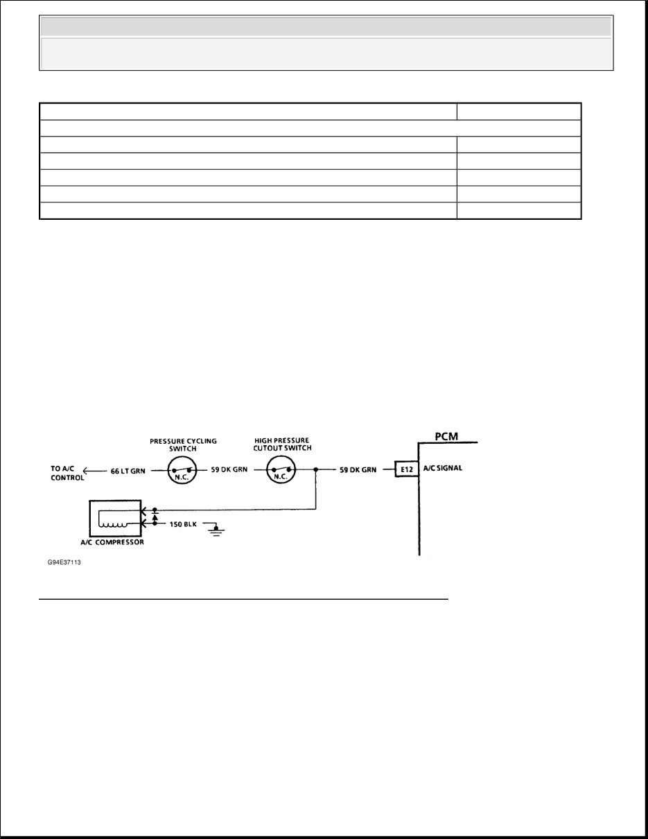
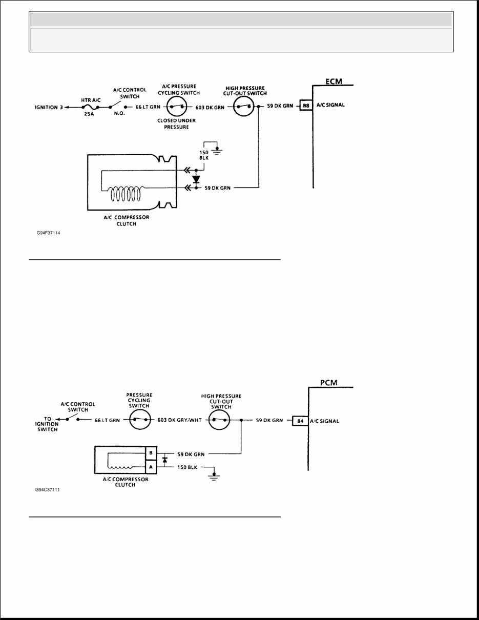
A/C COMPRESSOR CLUTCH CHART INDEX SCAN TESTER A variety of information is transmitted through Data Link Connector (DLC) terminal "E" or "M", depending on engine. This data is transmitted at a high frequency which requires a Tech 1 scan tester for interpretation. Several scan testers are available for diagnostic work. Scan testers other than Tech 1 scan tester will function and provide information for diagnostic work; however, some flow charts will specify a Tech 1 scan tester. Failure to use a Tech 1 scan tester when specified may result in incorrect diagnosis of a system. A/C COMPRESSOR CLUTCH CHARTS A/C REQUEST SIGNAL CIRCUIT DIAGNOSIS (4.3L, 5.0L, 5.7L, 7.4L) Fig. 1: A/C Request Signal Ckt. Diagnostic Schematic 4.3L, 5.0L, 5.7L, 7.4L A/C REQUEST SIGNAL CIRCUIT DIAGNOSIS (M/T) Turning on A/C system supplies battery voltage to A/C compressor clutch and Engine Control Module (ECM) terminal B8 through circuit No. 59, increasing idle speed. ECM does not control A/C compressor clutch. If A/C compressor clutch is malfunctioning, repair basic A/C system problem. If A/C system is operating properly and idle speed drops too low when A/C compressor turns on or flares too high when A/C compressor turns off, check for an open circuit No. 59 to ECM. If circuit No. 59 is okay, repair faulty ECM connection or replace faulty ECM. Application Figure No. "C" & "K" Series 4.3L VIN Z 1-2 5.0L VIN H 1-2 5.7L VIN K 1-2 6.5L VIN F, P & S 3 7.4L VIN N 1-2 1994 Chevrolet Pickup C1500 A/C COMPRESSOR CLUTCH CONTROLS 1994 AIR CONDITIONING & HEAT General Motors Corp. A/C Compressor Clutch Controls
Fig. 2: A/C Request Signal Circuit Diagnostic Schematic (M/T) A/C REQUEST SIGNAL CIRCUIT DIAGNOSIS (6.5L) Turning on A/C system supplies battery voltage to A/C compressor clutch and Powertrain Control Module (PCM) terminal B4 through circuit No. 59, increasing idle speed. PCM does not control A/C compressor clutch. If A/C compressor clutch is malfunctioning, repair basic A/C system problem. If A/C system is operating properly and idle speed drops too low when A/C compressor turns on or flares too high when A/C compressor turns off, check for an open circuit No. 59 to PCM. If circuit No. 59 is okay, repair faulty PCM connection or replace faulty PCM. Fig. 3: A/C Request Signal Circuit Diagnostic Schematic (6.5L) 1994 Chevrolet Pickup C1500 A/C COMPRESSOR CLUTCH CONTROLS 1994 AIR CONDITIONING & HEAT General Motors Corp. A/C Compressor Clutch Controls
1994 AIR CONDITIONING & HEAT MANUAL A/C DESCRIPTION SYSTEM DESCRIPTION The A/C system is a Cycling Clutch Orifice Tube (CCOT) type with a fixed displacement compressor and pressure cycling switch to control evaporator temperature. Electric motors are used to control mode, temperature and recirculation doors. A series of relays and a resistor are used to control blower speed. Motors and relays are controlled by a microprocessor-driven control panel (A/C controller). See Fig. 1 . A/C-heater system is a blend-air system. Air entering vehicle passes through evaporator core and through, or around, heater core to provide desired temperature. Suburban may be equipped with an optional auxiliary (rear unit) A/C or A/C-heater system. Auxiliary system operates with main A/C-heater system, but has separate blower controls. See Fig. 3 and Fig. 4 . CAUTION: When discharging air conditioning system, use only approved refrigerant recovery/recycling equipment. Make every attempt to avoid discharging refrigerant into the atmosphere. CAUTION: When battery is disconnected, radio will go into anti-theft protection mode. Obtain radio anti-theft protection code from owner prior to servicing vehicle. 1994 Chevrolet Pickup C1500 1994 AIR CONDITIONING & HEAT MANUAL A/C
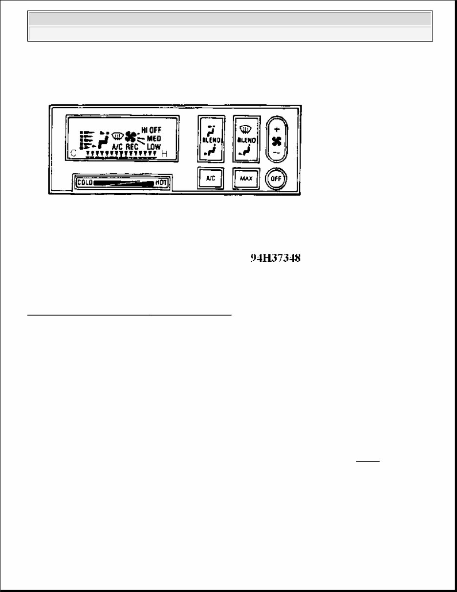
Fig. 1: Identifying Manual A/C - Heater Control Panel Courtesy of GENERAL MOTORS CORP. OPERATION AUXILIARY BLOWER CONTROLS Front blower control switch for auxiliary system is located above front seats. Rear blower control switch for auxiliary system is located above center seat. To operate auxiliary system from rear control, turn main A/C system on, then turn front control switch to REAR CNTL position. Auxiliary system can be operated separately from main system. MAIN CONTROL PANEL Air Control Switches The 2 BLEND buttons, located on right side of display, control airflow. Airflow is directed to defrost, heater and vent outlets. Amount of blending is shown on display by arrow moving between stick figure's feet and head. Blower Control Switch NOTE: For location of control panel switches, refer to illustration. See Fig. 1 . 1994 Chevrolet Pickup C1500 1994 AIR CONDITIONING & HEAT MANUAL A/C
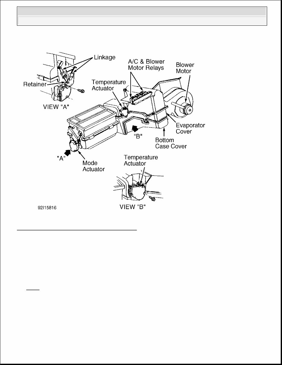
Main blower control switch can increase or decrease fan speed. The setting selected will appear on display as LOW, MED LOW, MED HI or HI. MAX Switch When MAX button is pushed, air in vehicle will be recirculated for maximum cooling. REC light will be shown on display. Temperature Selector Bar Bar under display controls temperature of air entering vehicle. Press COLD or HOT for desired temperature. Temperature is shown on display by arrows moving between "C" and "H". ADJUSTMENTS ACTUATORS To access actuator, remove instrument panel or glove box. Turn ignition switch to ACC position. Allow actuator to position itself. Turn ignition off, and reinstall components. See Fig. 2 . 1994 Chevrolet Pickup C1500 1994 AIR CONDITIONING & HEAT MANUAL A/C
Fig. 2: Locating Actuators & Blower Motor Relays Courtesy of GENERAL MOTORS CORP. TROUBLE SHOOTING A/C system has on-board diagnostic capabilities. Whenever a fault is detected, characters flash on control panel. See Fig. 1 . LOW REFRIGERANT CHARGE DETECTION When low refrigerant level is detected, low refrigerant charge detector shuts A/C system down. Letters A/C will flash on control panel for 2 minutes at each ignition switch ON cycle until refrigerant level is corrected and battery is disconnected to allow control head to reset. NOTE: Before performing trouble shooting procedures, ensure A/C-heater fuse is not blown. 1994 Chevrolet Pickup C1500 1994 AIR CONDITIONING & HEAT MANUAL A/C
MODE DOOR FAULT DETECTION When mode door fault is detected, arrows moving between stick figure's feet and head on control panel will flash for 2 minutes at each ignition switch ON cycle and each mode selection, until condition is repaired. TEMPERATURE DOOR FAULT DETECTION When temperature door fault is detected, all temperature arrows between "C" and "H" will flash for 2 minutes at each ignition switch ON cycle and each temperature selection, until condition is repaired. OPERATIONAL TESTING When trouble shooting and diagnosing an air conditioning system, always refer to appropriate vacuum and wiring diagrams for the system involved. If blower operates at all speeds and compressor clutch engages, electrical circuits are functioning properly. If evaporator inlet pipe and accumulator surface appear to be the same temperature when felt by hand, system is properly charged with refrigerant. Ensure vacuum and diaphragm function properly when moving selector control. BLOWER MOTOR WILL NOT RUN Check fuses. Turn ignition switch to RUN position. Check for voltage at function control switch. Switch blower switch to HI position. Check for voltage at switch and at high-speed blower relay. Ground blower motor with ignition switch in RUN position. If blower operates, motor is okay. BLOWER DOES NOT OPERATE IN HI Check for voltage at high-speed blower relay with ignition switch in RUN position and blower switch in HI position. If voltage is not present, check for voltage at blower switch. BLOWER OPERATES ONLY IN HI Check blower resistors for open condition. Check blower switch for voltage in each position. BLOWER OPERATES IN HI WITH IGNITION OFF Check blower motor relay. A/C DOES NOT WORK With engine running and function control switch at NORM position, check for voltage at pressure cycling switch. Check for voltage between pressure cycling switch and compressor clutch. Ground compressor clutch circuit. If clutch engages, check wide-open throttle cut-out switch and A/C compressor cut-off switch. INSUFFICIENT COOLING 1994 Chevrolet Pickup C1500 1994 AIR CONDITIONING & HEAT MANUAL A/C
Quick Check Procedure 1. Engine must be at normal operating temperature (not on fast idle or cold enrichment). Open vehicle doors and engine hood. Select NORM A/C position. Move temperature lever to COLD position. Turn blower switch to HI position. Engine should be at normal slow idle speed. 2. While compressor is engaged, feel temperature of accumulator surface and evaporator inlet pipe. If temperature of both components is the same (slightly cooler than ambient air), system is normal. If inlet pipe is frosted or feels cooler than accumulator surface, refrigerant charge is low. 3. Add refrigerant in 4-ounce increments, allowing system to stabilize between additions, until accumulator and pipe appear to be same temperature. Add 14 more ounces of refrigerant. CCOT SYSTEM, INSUFFICIENT COOLING CHART "A" NOTE: QUICK CHECK procedure may be used to check for proper refrigerant charge in A/C system, provided ambient air temperature is more than 70°F (21°C). On vehicles with Cycling Clutch Orifice Tube (CCOT) system, compressor will cycle on and off to meet system requirements. CCOT system does not use a sight glass to check refrigerant charge. 1994 Chevrolet Pickup C1500 1994 AIR CONDITIONING & HEAT MANUAL A/C
If you are in need of a repair manual for your 1995 Chevrolet C1500, look no further. Our comprehensive repair manual software is now available in a convenient digital format, making it an ideal resource for both professional mechanics and DIY enthusiasts.
Gone are the days of relying on traditional paper manuals, which were not only more expensive but also less convenient. Our accessible repair manual software covers all aspects of the Chevrolet C1500 and offers a cost-effective and user-friendly alternative to traditional manuals.
Whether you are looking to address brake issues, replace suspension components, troubleshoot engine problems, or perform standard maintenance, our repair manual software provides all the necessary information. From brakes, engine, suspension, and steering to drivetrain, electrical systems, heating, and air conditioning, this manual has got you covered.
By utilizing this repair manual software, you can save a significant amount of money on vehicle maintenance and repairs. Professional mechanics often charge high fees for their services, making a DIY approach not only cost-effective but also empowering. The manual is designed for easy use and is compatible with Windows, Mac computers, smartphones, and tablets, ensuring accessibility across various devices.
Recently Viewed
5,521,897Happy Clients
2,594,462eManuals
1,120,453Trusted Sellers
15Years in Business
Price:
Actual Price:
1995 Chevrolet C1500 Service & Repair Manual Software