2006-2013 Cherry QQ6 (S21) Service & Repair Manual
What's Included?
Lifetime Access
Fast Download Speeds
Offline Viewing
Access Contents & Bookmarks
Full Search Facility
Print one or all pages of your manual
Service Manual For CHERY QQ6 (Maintenance And Care) After Sales Service Department of Chery Automobile Sales Co., Ltd
TABLE OF CONTENTS Chapter 1 Overview of Vehicle ......................................................................................................... 4 1. Overview of Engine ................................................................................................................. 4 2. Overview of Transmission ....................................................................................................... 4 3. Rubbing Numbers .................................................................................................................... 4 3.1. Vehicle Identification Number (VIN) ........................................................................... 4 3.1.1. VIN position....................................................................................................... 4 3.1.2. Meaning of VIN code ........................................................................................ 5 3.2. Engine Number ............................................................................................................. 6 3.2.1. Engine number position ..................................................................................... 6 3.2.2. Meaning of Engine Number ............................................................................... 6 3.3. Transmission Number ................................................................................................... 9 3.3.1. QR513 series transmission nubmer position ...................................................... 9 3.3.2. Meaning of QR513 series transmission number ................................................ 9 Chapter 2 Technical Specifications ................................................................................................. 11 1. Specification Table................................................................................................................. 11 1.1. Engine specification table ........................................................................................ 11 1.2. Transmission specification table ................................................................................. 11 2. Oil/Fluid Capacity Table ........................................................................................................ 12 3. Oil/Fluid Specifications Table ............................................................................................... 12 Chapter 3 Basic Operation and Adjustment .................................................................................... 13 1. Vehicle Delivery Check ......................................................................................................... 13 1.1. Interior and exterior .................................................................................................... 13 1.2. Engine compartment section ....................................................................................... 13 1.3. Manipulation and control section................................................................................ 13 1.4. Engine startup check ................................................................................................... 13 1.5. Engine shutdown check .............................................................................................. 14 1.6. Each light turnoff check .............................................................................................. 14 1.7. All doors open check................................................................................................... 14 1.8. Vehicle uplift check..................................................................................................... 15 1.9. Vehicle jackdown c.Check .......................................................................................... 15 1.10. Final check ................................................................................................................ 15 1.11. Final preparation ....................................................................................................... 15 2. Vehicle Jack Lift Points ......................................................................................................... 15 2.1. Position of front jack lift point .................................................................................... 15 2.2. Position of rear jack lift point ..................................................................................... 16 3. Towing ................................................................................................................................... 16 3.1. Towing position........................................................................................................... 16 3.2. Towing method ........................................................................................................... 17 4. Instrument Setting .................................................................................................................. 17 4.1. Clock setting ............................................................................................................... 17 4.2. Mileage setting ............................................................................................................ 18
4.3. Maintenance indicator light reset ................................................................................ 18 5. Battery Check ........................................................................................................................ 18 6. Airbag Check ......................................................................................................................... 18 7. Engine Oil Check ................................................................................................................ 19 7.1. Oil level check ............................................................................................................ 19 7.2. Method to replace the engine oil ................................................................................. 19 8. Transmission Oil Check ......................................................................................................... 20 8.1. Oil level check ............................................................................................................ 20 8.2. Method to replace the transmission oil ....................................................................... 20 9. Trouble Diagnosis of Electronic Control System................................................................... 20 10. Lubrication and Maintenance of All Hinges and Door Locks ............................................. 21 11. Wiper System Check ............................................................................................................ 21 11.1. Wiper blade check and maintenance ......................................................................... 21 11.2. Nozzle check and adjustment .................................................................................... 21 12. Coolant Check...................................................................................................................... 22 13. Check and Maintenance of Windscreen Cleaning Fluid ...................................................... 23 14. Tire Check............................................................................................................................ 24 14.1. Pattern depth check ................................................................................................... 24 14.2. Tire pressure check ................................................................................................... 24 15. Timing Belt Check ............................................................................................................... 24 16. Check and Maintenance of Engine Accessaries’ Belts......................................................... 25 17. Check and Adjustment of Clutch ......................................................................................... 25 18. Check and Maintenance of Brake System ........................................................................... 25 19. Check and Maintenance of Vehicle Bottom......................................................................... 26 20. Check and Maintenance of Intake and Exhaust Systems ..................................................... 28 21. Check and Maintenance of Fuel System.............................................................................. 28 22. Check and Maintenance of Steering System........................................................................ 28 23. Check and Maintenance of A/C System .............................................................................. 29 24. Check and Replacement of Three Filters ............................................................................. 30 25. Four-Wheel Alignment Check ............................................................................................. 31 26. Lamp Check ......................................................................................................................... 32 27. Exhaust Emission................................................................................................................. 33 Chapter 4 Regular Maintenance Specifications ............................................................................ 33 1. Regular Maintenance Schedule.............................................................................................. 33 2. Regular Maintenance Process ................................................................................................ 35 2.1. Standard first maintenance (5,000 KM) work procedure ............................................ 35 2.2. Standard 15,000 KM maintenance work procedure .................................................... 37 2.3. Standard 30,000 KM maintenance work procedure .................................................... 39
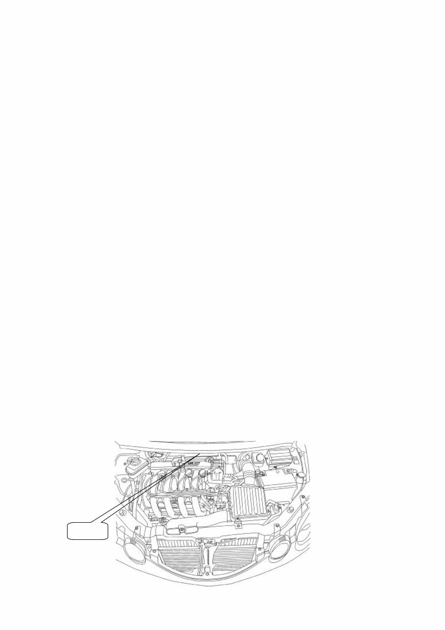
Chapter 1 Overview of Vehicle 1. Overview of Engine The QQ6 car is equipped with a engine of 1.3L or 1.1L displacements which is developed and produced by CHERY Automobile Co.. Ltd. The models of the eninge are: SQR473 F and SQR472 F respectively. Two kinds of engines have the following characteristics: SQR473 F series: Vertical, four cylinders, water-cooled, 4 strokes, in-line, double overhead camshaft, 4 valves, multipoint electronic gasoline injection. SQR472 F series: Vertical, four cylinders, water-cooled, 4 strokes, in-line, double overhead camshaft, 4 valves, multipoint electronic gasoline injection. 2. Overview of Transmission QQ6 car is equipped with two kinds of manual transmissions developed by CHERY Automobile Co.. Ltd.: QR513MHA and QR512. These transmissions have the following characteristics: QR513MHA: Integrated variable differential transmission, two shafts, five gears (five forward gears, one reverse gear), five forward gears have a synchronizer. QR512: Integrated variable differential transmission, two shafts, five gears (five forward gears, one reverse gear), five forward gears have a synchronizer. 3. Rubbing Numbers 3.1. Vehicle Identification Number (VIN) 3.1.1. VIN position VIN code is engraved on the lower of gutter channel at front side of the vehicle, as shown in the figure below: VIN Code
3.1.2. Meaning of VIN code 1) The VIN code is structured according to the requirements of GB16735. □□□ □□○○□○ □○ ○○○○○○ World Manufacturer Identifier Code 2) The application for the World Manufacturer Identifier (WMI) Section is submitted by the CHERY Company to the Bureau of Automotive Industry of the Ministry of Machinery Industry. P.R China. Now, the CHERY Automobile Co., Ltd.’ s WMI code is LVV. 3) The Vehicle Descriptor Section (VDS) consists of manufacturer, body style and driving type, transmission type, engine type, constraint system type and check digit. i. The first character of VDS section identifies the make of the vehicle, and the CHERY brand vehicle is represented as the character D. ii. The second character of VDS section represents the body style and driving type: A for the three-compartment fiver-door 4×2 type; B for the two-compartment five-door 4×2 type; C for the three-compartment four-door 4×2 type: D for the two-compartment five-door 4×4 type; E for the two-compartment four-door 4×2 type, F for the three-compartment two-door 4×2 type; and G for the two-compartment three-door 4×2 type. iii. The third character of VDS section means the transmission type, where the digit 1 represents the manual transmission and 2 for automatic transmission. iv. The fourth character of VDS section represents the engine type, where the digit 1 represents the 1.5L - 2.0L (2.0L exclusive) series EFI gasoline engine; digit 2 for the 1.5L (1.5L exclusive) or below EFI gasoline engine; digit 4 for the 2.0L - 2.5L (2.5L exclusive) series EFI gasoline engine. v. The fifth character of VDS section identifies the constraint system, where the character A represents the seat belt, and the character B for the seat belt + air bag. 4) The sixth character of VDS section is the check digit whose purpose is to provide a means for verifying the accuracy of any VIN transcription. After the other 16 characters in VIN have been determined, the check digit shall be calculated. The Vehicle Indicator Section (VIS) consists of vehicle model year, plant of manufacture, and sequential number. ① The first character of VIS section represents the vehicle model year. The year shall be designated as indicated in Table 1 as follows: Table 1 Year Code Year Code Year Code Year Code 1999 X 2002 2 2005 5 2008 8 2000 Y 2003 3 2006 6 2009 9 2001 1 2004 4 2007 7 2010 A Manufacturer Body Style and Driving Type Transmission Type Engine Tyep Constraint System Type Check Digit Model Year Assembly Plant Sequential Number VDS Section VIS Section WMI Section
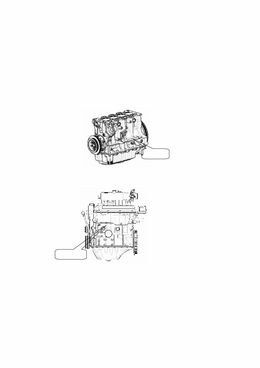
② The second character of VIS section represents the plant of manufacture. The CHERY Automobile Co., Ltd. is represented as the character D. ③ The third through the eighth of VIS section represents the number sequentially assigned by the manufacturer in the production process. The number is assigned yearly, starting from 000001. 3.2. Engine Number 3.2.1. Engine number position 1). Number of SQR473F series engine is printed on the boss of cylinder body near the engine exhaust side oil cleaner (as shown in the figure below). 2). Number of SQR472F series engine is printed on the boss of cylinder body over the engine exhaust side oil cleaner (as shown in the figure below). 3.2.2. Meaning of Engine Number As shown in the figure above, the engine number located at the engine block consists of engine type and serial sumber. 1. Engine type The engine type conforms to the requirements of GB725, which consists of enterprise code, number of engine cylinders, bore, feature code and differentiation code. A complete engine type is structured as follows: Engine No Engine No
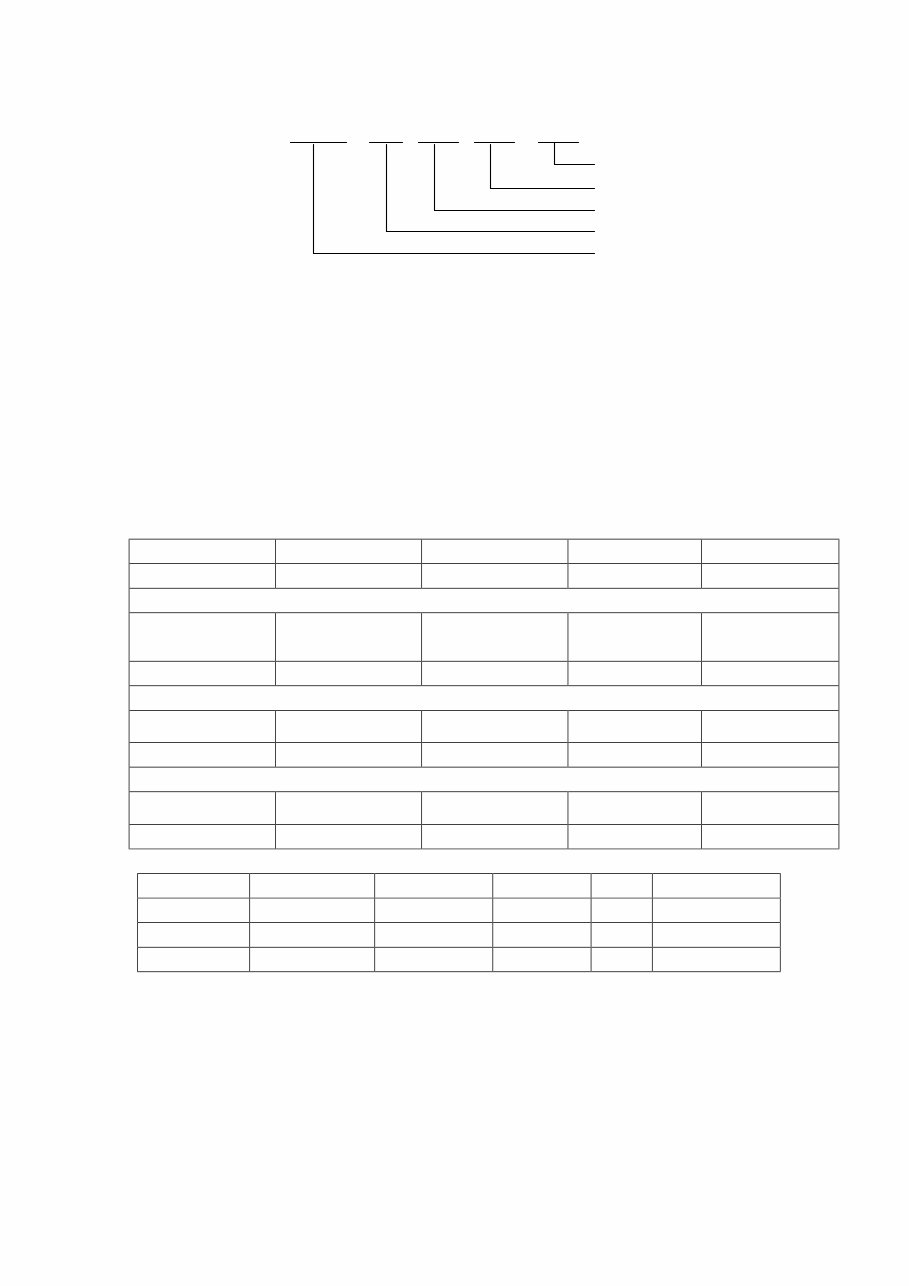
□□□ ○ ○○ □ □ where, ○ represents an arabic numeral, and □ represents an alphabetic character. 1.1 The enterprise code is fixed as SQR; 1.2 The number of engine cylinders is a 1 to 2-digit integer; 1.3 The bore is the diameter of cylinder barrel, expressed by a 2 to 3-digit integer, and its decimal is rounded to ainteger with the unit of mm according to the rounding principle. 1.4 Feature code: Represent the basic feature of an engine, expressed with a capital English alphabet, and its meaning is shown in Table 1. If multiple features in Table 1 appear at the same time, a feature code is choosed in turn according to the sequence specified in Table 2. In case that the line engine’ s basic feature code L is omitted, the other feature codes in Table 2 can be choosed in turn according to the sequence of these codes. Table 1 Feature Code of Engine Engine Characteristics Line engine V-engine Feature Code L V Engine Characteristics Direct injection Gasoline combustion rate variable valve timing Feature Code J H Engine Characteristics Diesel natural aspirationi Diesel turbo Diesel turbo intercooler Gasoline turbo intercooler Feature Code D T A B Engine Characteristics Carburetor Single point injection Two-valve multipoint injection Four-valve multipoint injection Feature Code C M E F Table 2 Sequence of Engine Feature Code Optional 1 st Structure Line L (omitted) V 2 nd Special technique J H 3 rd Air intake D T A B 4 th Fuel supply C M E F 1.5 Differentiation code: Expressed with a capital English alphabet, used as a complementary code to differentiate the type of engine when all the number of engine cylinders, bore and feature code are the same while the structure, main parameter(s) or fuel supply method and etc change (e.g., the change of engine stroke, bifuel engine, etc). For the change of engine’s peripheral parts (such as intake and exhaust manifolds), the engine type is invaried but differeniated by changing the number of engine assy. 1.6. Example of engine type: “SQR473F” means a 4-cylinders, 73 mm bore , line gasoline engine manufactured by the CHERY Automobile Feature Code Bore Differentiation code Enterprise Code Number of Cylinders
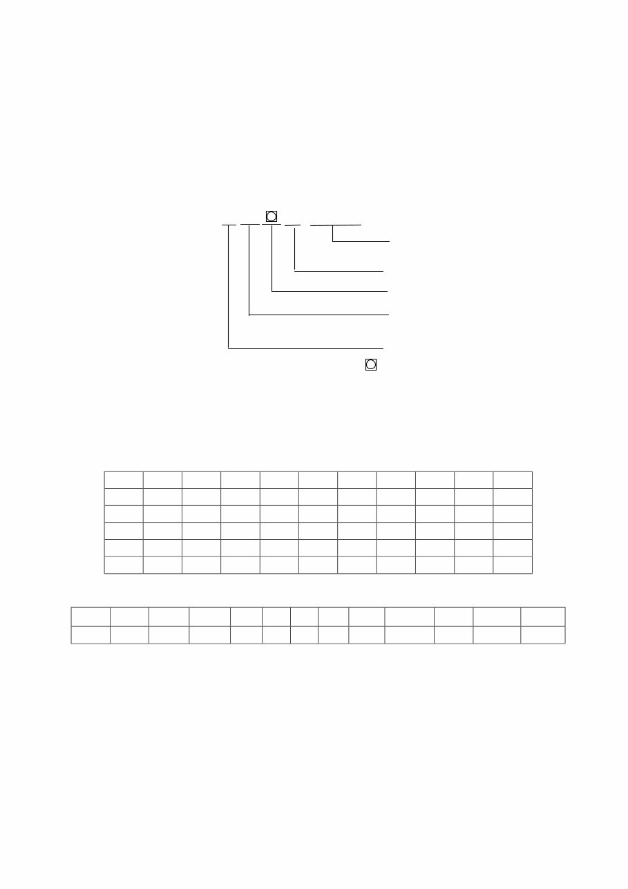
Co., Ltd., which is a four-valve multipoint injection engine (the line gasoline engine feature code “L” is omitted and then is occupied by the “four-valve multipoint injection, and the first structure differentiation code A is also omitted). 2. Serial number The serial number of an engine consists of engine feature code, EFI system manufacturer code, manufacture year code, month code, the number sequentially assigned by the manufacturer of the engine in the production month of this type of engines and the start/end symbol *. A complete serial number for an engine is as follows: * □ □ □ ○○○○○ * Month Code where ○ represents an arabic numeral, □ represents an alphabet, represents an arabic numeral or alphabet. 2.1. The engine feature code is performed according to the provisions in paragraph 2.1.4. 2.2. EFI system manufacturer: C – Motorola; D – Marelli; E – Delphi; F – United Automotive Electronic Systems (UAES) Co., Ltd.; G – Siemens; H – TROITEC Automotive Electronics Co., Ltd.; B – Bosch 2.3. The year and month codes are performed in accordance with Tables 3 and 4 respectively. Table 3 Characters used for designating the year (recycleable) Year 2001 2002 2003 2004 2005 2006 2007 2008 2009 2010 Code 1 2 3 4 5 6 7 8 9 A Year 2011 2012 2013 2014 2015 2016 2017 2018 2019 2020 Code B C D E F G H J K L Year 2021 2022 2023 2024 2025 2026 2027 2028 2029 2030 Code M N P R S T V W X Y Table 4 Characters used for designating the month Month January February March April May June July August September October November December Code A B C D E F G H J K L M 2.4. Example of serial number “*FF5H00106*” means the 106 th UAES four-valve multipoint EFI engine manufactured in August 2005. EFI System Manufacturer Code Sequential number in this producetion month Year Code Feature Code
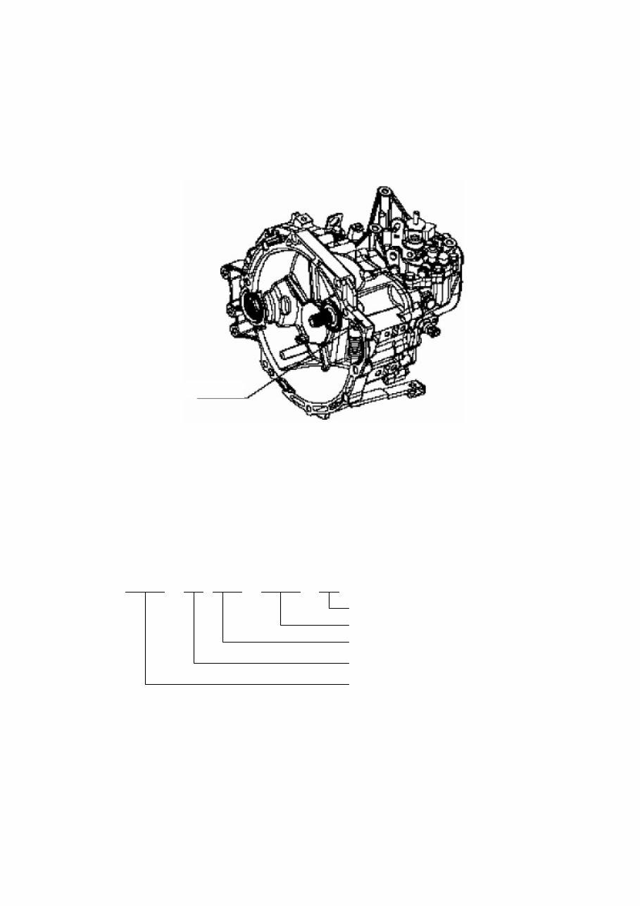
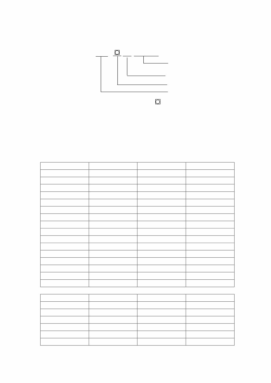
3.3. Transmission Number 3.3.1. QR513 series transmission nubmer position The position of QR513 series transmission number is as shown in the figure: 3.3.2. Meaning of QR513 series transmission number The number of QR513 series transmission consists of transmission type and serial number. 1). Transmission type The transmission type consists of code QR, number of transmission gears, max transmission torque, feature code and structure differentiation code. A complete transmission type is as follows: □ □ ○ ○○ □ □ □ Structure Differentiation Code Feature Code Max Transmission Torque (kg·m) Number of Transmission Gears Code QR where, ○ represents an arabic numeral, and □ represents an alphabet. 2). Serial number The serial number consists of the suffix of assy part code number (AA for the part code number without suffix), manufacture year code, month code, the number sequentially assigned by the manufacturer of the transmission in the production month of this type of transmission and the start/end symbol *. The year and month codes are performed according to Tables 3 and 4 respectively. Position of Number
A complete seiral number for a transmission is as follows: * □ □ □ □ ○○○○○ * Month Code where, ○ represents an arabic numeral, □ represents an alphabet, and represents an arabic numeral or alphabet. The suffix is located the last portion of the part code number, and unavailable for the basic type transmission.. In case that its structure, dimension, materials, heat treatment requirements, surface treatment and etc of part and assy are changed on basis of the original products, the suffix shall be modified. In the codes, the English alphabets shall be capital ones, and used in ture starting from A. To avoid the confusion, the alphabets “I ”, “O” and “X” shall not be used. When the modification makes no influence on the interchangeability, the alphabet A shall take the lead; and if the modification makes an influence on the interchangeability, the alphabet A shall be neglected and B takes the lead. Table 5 Characters used for designating the year Year Code Year Code 1999 X 2015 F 2000 Y 2016 G 2001 1 2017 H 2002 2 2018 J 2003 3 2019 K 2004 4 2020 L 2005 5 2021 M 2006 6 2022 N 2007 7 2023 P 2008 8 2024 R 2009 9 2025 S 2010 A 2026 T 2011 B 2027 V 2012 C 2028 W 2013 D 2029 X 2014 E 2030 Y Table 2 Characters used for designating the month Month Code Month Code January A July G February B August H March C September J April D October K May E November L June F December M Sequential number in this producetion month Year Code Suffix of Assy Part Code Nubmer
The service manual has been meticulously prepared to enhance the quality of repairs by providing the serviceman with precise insights into the product and the correct repair procedures. It is an invaluable resource for both professional mechanics and DIY enthusiasts.
This Service and Repair Manual covers the following models:
CHERRY QQ6 (S21), Years 2006-2013 Workshop Service Manual
This comprehensive service manual includes detailed information on the following:
BODY ACCESSORIES AND DIMENSIONS
Engine Hood and Luggage Compartment
Disassembly/Reassembly of Interior Decorations
Removal and Maintenance of Door
Disassembly/Reassembly and Maintenance of Front/Rear Bumper
Disassembly/Reassembly and Maintenance of Headlamp and Fog Lamp
Disassembly/Reassembly of Ceiling
Disassembly/Reassembly of Instrument Panel
Air Conditioning (A/C) System
Body Dimension
Wire Harness
CHASSIS
Brake System
Adjustment of Suspension System And Four-Wheel Alignment System
Disassembly/Reassembly and Maintenance of Steering System
ELECTRICAL, CIRCUIT
Control Principle of Some Systems
BCM Control
Fog and Position Lamps Control
Headlamp Control
Turn Signal Lamp Control
Electric Rear-View Mirror
Wiper Motor Control
Schematic Diagrams of Circuit Control
Definition of Main Harness Connectors
Drawing Description
Schematic Diagram of Main Electric Box and Module Position
Electrical Box Description
Schematic Diagrams of Circuit Control
MAINTENANCE AND CARE
Overview of Vehicle
Technical Specifications
Basic Operation and Adjustment
Regular Maintenance Specifications
TRANSMISSION CASE
Introduction of QR513 Transmission
Decomposition of QR513 Transmission
Assembly and Regulation of QR513 Transmission
General Failures and Troubleshooting
ENGINE-MECHANICAL
Introduction of Characteristics
Specification
Special Tools
Measurement of Cylinder Pressure
Disassembly of Power-assisted Steering System
Disassembly of A/C Compressor
Disassembly of Generator
Replacement of Engine Timing Belt
Disassembly of Engine Assembly
Disassembly of Intake Manifold
Disassembly of Cylinder Head
Disassembly and Installation of Oil Pump and Lubrication System
Disassembly of Crank-Connecting Rod Mechanism
ENGINE
Disassembly and Installation of Electronic Fuel Injection System
Principle of Electronic Fuel Injection System
Fundamental Principle for Failure Diagnosis of Electronic Fuel Injection System
... and more
This service manual is an essential resource for both professional mechanics and DIY enthusiasts. It provides detailed substeps, notes, cautions, warnings, numbered instructions, and detailed illustrations to guide you through each service and repair procedure. The manual also facilitates troubleshooting and electrical service procedures with detailed wiring diagrams for ease of use.
Product Details:
Brand: CHERRY
Model: QQ6 (S21)
Years: 2006-2013
Language: English
Format: Adobe Acrobat Document (.PDF) / (.OVA)
Compatible: All Versions of Windows & Mac
Recently Viewed
5,521,897Happy Clients
2,594,462eManuals
1,120,453Trusted Sellers
15Years in Business
Price:
Actual Price:
2006-2013 Cherry QQ6 (S21) Service & Repair Manual

 Years 2006-2013 Workshop Service Manual")