

2010-2011 Cadillac SRX Service & Repair Manual
What's Included?
Fast Download Speeds
Online & Offline Access
Access PDF Contents & Bookmarks
Full Search Facility
Print one or all pages of your manual
CADILLAC
SRX
BRAKES 22-10 • DRIVE TRAIN 22-19
ANTI-LOCK BRAKE SYSTEM
(ABS) 22-10
General Information 22-10
Precautions 22-10
Speed Sensors 22-10
Removal & Installation: 22-10
BLEEDING THE BRAKE
SYSTEM 22-11
Bleeding Procedure .". 22-11
Bleeding the ABS
System 22-11
Fluid Fill Procedure 22-13
Hydraulic Brake System
Bleeding 22-12
Master Cylinder Bench.
Bleeding 22-13
FRONT DISC BRAKES 22-14
Brake Caliper 22-14
Removal & Installation. 22-14
Disc Brake Pads 22-14
Removal & Installation 22-14
PARKING BRAKE 22-16
Parking Brake Cables 22-16
Adjustment 22-16
Parking Brake Shoes 22-16
Parking Brake Adjuster
Disabling... 22-17
Parking Brake Adjuster
Enabling :22-17
Removal & Installation 22-16
REAR DISC BRAKES 22-15
Brake Caliper..... 22-15
Removal & Installation 22-15
Disc Brake Pads ....22-16
Removal & Installation 22-16
CHASSIS ELECTRICAL 22-18
AIR BAG (SUPPLEMENTAL
RESTRAINT SYSTEM) 22-18
General Information .' 22-18
Arming the System 22-18
Clockspring Centering 22-19
Disarming the System 22-18
Service Precautions 22-18
Automatic Transmission
Fluid 22-19
Checking Fluid ....22-19
Fluid Refill .22-19
Front Halfshaft 22-21
Removal & Installation 22-21
Rear Axle Fluid -. 22-21
Drain & Refill 22-21
Rear Driveshaft (Propeller
Shaft) 22-22
Removal & Installation 22-22
Rear Halfshaft 22-22
Removal & Installation 22-22
Transfer Case Assembly 22-20
Removal & Installation 22-20
ENGINE COOLING 22-23
Engine Coolant 22-23
Drain & Refill Procedure 22-23
Flushing 22-23
Engine Fan 22-23
Removal & Installation 22-23
Radiator 22-24
Removal & Installation 22-24
Thermostat 22-24
Removal & Installation 22-24
Water Pump 22-24
Removal & Installation 22-24
ENGINE ELECTRICAL 22-25
BATTERY SYSTEM 22-25
Battery 22-25
Removal & Installation 22-25
CHARGING SYSTEM 22-26
Alternator 22-26
Removal & Installation 22-26
IGNITION SYSTEM 22-26
Firing Order 22-26
Ignition Coil 22-26
Removal & Installation 22-26
Ignition Timing 22-26
Adjustment 22-26
SparkPlugs 22-26
Removal & Installation...' 22-26
STARTING SYSTEM 22-27
Starter 22-27
Removal & Installation 22-27
ENGINE MECHANICAL 22-27
Accessory Drive Belts 22-27
Accessory BELT Routing 22-27
Adjustment 22-27
Inspection 22-27
Removal & Installation 22-27
Air Cleaner 22-27
Filter/element
Replacement 22-28
Removal & Installation 22-27
Camshaft and Valve Lifters 22-28
Inspection 22-28
Removal & Installation 22-28
Catalytic Converter/
Exhaust Manifold 22-30
.Removal & Installation 22-30
Crankshaft Front Seal 22-32
Removal & Installation 22-32
Cylinder Head 22-32
Removal & Installation 22-32
Engine Oil & Filter 22-34
Replacement 22-34
Exhaust Manifold 22-34
Removal & Installation 22-34
Intake Manifold • 22-35
Removal & Installation 22-35
Oil Pan 22-35
Removal & Installation 22-35.
Oil Pump..... 22-36
Inspection 22-36
Removal & Installation 22-36
Piston and Ring ,...22-36
Positioning 22-36
Rear Main Seal 22-36
' Removal & Installation 22-36
Timing Chain & Sprockets 22-41
Removal & Installation 22-41
Timing Chain Front
Cover 22-37
Removal & Installation..: 22-37
Turbocharger 22-43
Removal & Installation 22-43
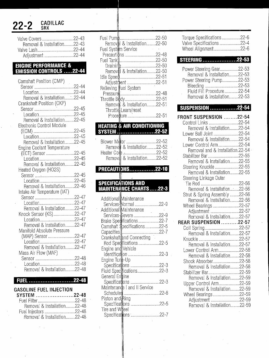
22-2
CADILLAC
SRX
Valve Covers 22-43
Removal & Installation 22-43
Valve Lash 22-44
Adjustment 22-44
ENGINE PERFORMANCE &
EMISSION CONTROLS .....22-44
Camshaft Position (CMP)
Sensor 22-44
Location 22-44
Removal & Installation :..22-44
Crankshaft Position (CKP)
Sensor : 22-45
Location 22-45
Removal & Installation 22-45
Electronic Control Module
(ECM) 22-45
Location 22-45
Removal & Installation 22-45
Engine Coolant Temperature
(ECT) Sensor 22-45
Location 22-45
Removal & Installation 22-45
Heated Oxygen (H02S)
Sensor -. 22-45
Location 22-45
Removal & Installation 22-46
Intake Air Temperature (IAT)
Sensor 22-47
Location 22-47
Removal & Installation 22-47
Knock Sensor (KS) 22-47
Location 22-47
Removal & Installation 22-47
Manifold Absolute Pressure
(MAP) Sensor 22-47
Location 22-47
Removal & Installation 22-47
Mass Air Flow (MAF)
Sensor 22-48
Location 22-48
Removal & Installation 22-48
FUEL.... .....22-48
GASOLINE FUEL INJECTION
SYSTEM 22-48
Fuel Filter 22-48
Removal & Installation 22-48
Fuel Injectors 22-48
Removaf & Installation 22-48
Tl
Fuel Pum
Remov
Fuel Syst
Precauti!
Fuel Tank
Drainir
Remov
Idle Speec
Adjustment
Relieving
Pressure
Throttle B
Remov
Throttle1
Proce
22-50
& Installation 22-50
Service
ns... 22-48
22-50
22-50
& Installation 22-50
22-51
22-51
uel System
22-48
dy 22-51
& Installation 22-51
Learn/reset
ure....'. 22-51
HEATING & AIR CONDITIONING
SYSTEM.! 22-52
Blower
Remove
Heater Coj
RemovE
.or 22-52
& Installation 22-52
i, 22-52
& Installation 22-52
PRECAUTIONS.. 22-10
SPECIFICATIONS AND
MAINTENANCE CHARTS 22-3
Additional
Services^
Additional
Services-
Brake Spei
Camshaft:
Capacities
Crankshaft
Rod Spec
Engine anc
Identifica
Engine Tur
Specificai
Fluid Speci
General En'
Maintenam
Schedule:
Piston and
Specificat
Tire and
Specificai
Maintenance
ormal 22-9
/laintenance
evere '. 22-9
ications 22-7
pecifications 22-5
22-7
.nd Connecting '
ications • 22-5
Vehicle
on..., 22-3
-Up
ons 22-3
ications 22-3
ine
Specificat ons 22-3
and II Service
{ing
ons.
eel
ons1.
.22-5
.22-7
Torque Specifications 22-6
Valve Specifications 22-4
Wheel Alignment 22-6
STEERING 22-53
Power Steering Gear 22-53
Removal & Installation 22-53
Power Steering Pump 22-53
Bleeding 22-53
Fluid Fill Procedure 22-54
Removal & Installation 22-53
SUSPENSION 22-54
FRONT SUSPENSION 22-54
Control Links 22-54
Removal & Installation 22-54
Lower BallJoint 22-54
Removal & Installation 22-54
Lower Control Arm 22-54
Removal and & lnstallation.22-54
Stabilizer Bar 22-55
Removal & Installation 22-55
Steering Knuckle 22-55
Removal & Installation 22-55
Steering Linkage Outer
Tie Rod 22-56
Removal & Installation...- 22-56
Strut & Spring Assembly 22-56
Removal & Installation 22-56
Wheel Bearings 22-57
Adjustment 22-57
Removal & Installation 22-57
REAR SUSPENSION 22-57
Coil Spring 22-57
Removal & Installation 22-57
Knuckle 22-57
Removal & Installation 22-57
Lower Control Arm 22-58
Removal & Installation 22-58
Shock Absorber 22-58
Removal & Installation 22-58
Stabilizer Bar 22-59
Removal & Installation 22-59
Upper Control Arm 22-59
Removal & Installation 22-59
Wheel Bearings 22-59
Adjustment 22-59
Removal & Installation 22-59
CADILLAC
SRX 22-3
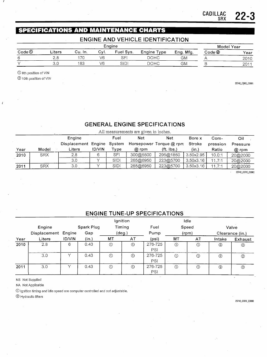
ENGINE AND VEHICLE IDENTIFICATION
Engine
Model Year
Code© Liters Cu. In. Cyl. Fuel Sys. Engine Type Eng. Mfg. Code® Year
6 170 V6 SFI DOHC GM A 2010
Y 3.0 183 V6 SIDI DOHC GM 2011
©8th position of VIN
© 10th position of VIN
25742_CSRX_C0001
GENERAL ENGINE SPECIFICATIONS
All measurements are given, in inches.
Engine Fuel Net Net Bore x Com- Oil
Displacement Engine System Horsepower Torque @ rpm Stroke pression Pressure
Year Model Liters ID/VIN Type @ rpm (ft. Ibs.) (in.) Ratio @ rpm
2010
2011
SRX
SRX
2.8
3.0
3.0
6
Y
Y
SFI
SIDI
SIDI
300@5500
265@6950
265@6950
295@1850
223@5700
223@5700
3.50x2.95
3.50x3.16
3.50x3.16
10.0:1
11.7:1
11.7:1
20@2000
20@2000
20@2000
25742_CSRX_C0002
ENGINE TUNE-UP SPECIFICATIONS
Ignition Idle
Engine Spark Plug Timing Fuel Speed Valve
Displacement Engine Gap
Year Liters IDA/IN (in.)
2010
2011
2.8
3.0
3.0
6
Y
Y
0.43
0.43
0.43
(deg.)
MT AT
©
©
©
©
©
©
Pump
(psi)
276-725
PSI
276-725
PSI
276-725
PSI
(rpm) Clearance (in.)
MT AT Intake Exhaust
©
©
©
©
©
©
©
©
©
©
©
©
NS Not Supplied
NA Not Applicable
© Ignition timing and idle speed are computer controlled and not adjustable.
@ Hydraulic lifters
25742_CSRX_C0003
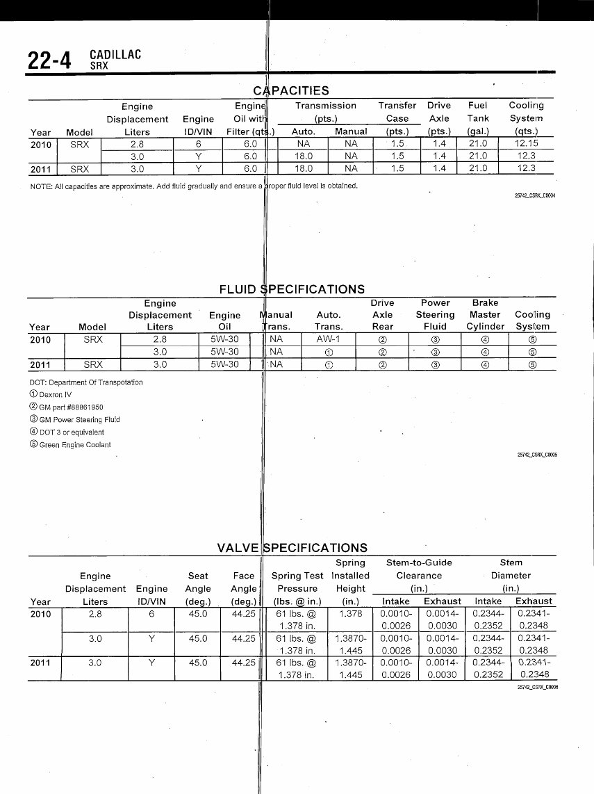
22-4
CADILLAC
SRX
C)
Engine Engine
Displacement Engine Oil with
Year Model Liters IDA/IN Filter (qt
2010 SF
2011 SF
RX 2.8 f
3.0 N
RX 3.0
3 6.0
< 6.0
{ 6.0 t
NOTE: All capacitiesare approximate. Add fluid gradually and ensure a
PACITIES
Transmission Transfer Drive Fuel Cooling
(pts.) Case Axle Tank System
.) Auto. Manual (pts.)
NA NA 1.5
18.0 NA 1.5
18.0 NA • 1.5
roper fluid level is obtained.
(pts.) (gal.) (qts.)
1.4 21.0 12.15
1.4 21.0 12.3
1.4 21.0 12.3
25742_CSRX_C0004
FLUID SPECIFICATIONS
Engine II Drive Power Brake
Displacement Engine lyjanual Auto. Axle Steering Master Cooling
Year Model Liters Oil
2010
2011
SRX
SRX
2.8
3.0
3.0
5W-30
5W-30
5W-30
Trans. Trans. Rear Fluid Cylinder System
NA
[NA
II'-NA
AW-1
®
©
©
©
©
®
• ©
©
©
©
©
©
©
©
DOT: Department Of Transpotation
© Dexron IV
©GM part #88861950
© GM Power Steering Fluid
©DOTS or equivalent
© Green Engine Coolant
25742_CSRX_C0005
VALVE
Engine Seat Face
Displacement Engine Angle Angle;
Year Liters IDA/IN (deg.) (deg.)
2010
2011
2.8
3.0
3.0
6
Y
Y
45.0
45.0
45.0
44.25
44.25 '
44.25
SPECIFICATIONS
Spring
Spring Test Installed
Pressure Height
(Ibs. @ in.) (in.)
61 Ibs. @
1.378 in.
61 Ibs. @
•1.378 in.
61 Ibs. @
1.378 in.
1.378
1.3870-
1 .4,45
1.3870-
1.445
Stem-to-Guide Stem
Clearance Diameter
(in.) (in.)
Intake Exhaust Intake Exhaust
0.0010-
0.0026
0.0010-
0.0026
0.0010-
0.0026
0.0014-
0.0030
0.0014-
0.0030
0.0014-
0.0030
0.2344-
0.2352
0.2344-
0.2352
0.2344-
0.2352
0.2341-
0.2.348
0.2341-
0.2348
0.234V
0.2348
25742_CSRX_C0006
CADILLAC
SRX 22-5
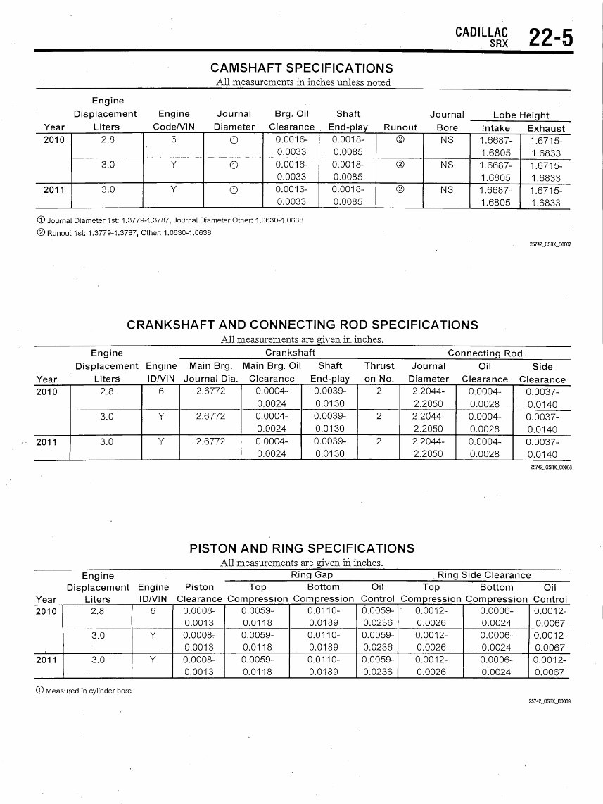
CAMSHAFT SPECIFICATIONS
All measurements in inches unless noted
Engine
Displacement Engine Journal Brg. Oil Shaft Journal
Year Liters Code/VIN Diameter Clearance . End-play Runout Bore
2010
2011
2.8
3.0
3.0
6
Y
Y
©
©
©
0.0016-
0.0033
0.0016-
0.0033
0.0016-
0.0033
0.0018-
0.0085
0.0018-
0.0085
0.0018-
0.0085
©
©
©
NS
NS
NS
Lobe Height
Intake Exhaust
1 .6687-
1.6805
1.6687-
1.6805
1.6687-
1.6805
1.6715-
1.6833
1.6715-
1.6833
1.6715-
1.6833
©Journal Diameter 1st: 1.3779-1.3787, Journal Diameter Other: 1.0630-1.0638
© Runout 1st: 1.3779-1.3787, Other. 1.0630-1.0638
25742_CSRX_C0007
CRANKSHAFT AND CONNECTING ROD SPECIFICATIONS
All measurements are given in inches.
Engine
Displacement Engine
Year Liters ID/VIN
2010
2011
2.8
3.0
3.0
6
Y
Y
Crankshaft Connecting Rod
Main Brg. Main Brg. Oil Shaft Thrust Journal Oil Side
Journal Dia. Clearance End-play on No. Diameter Clearance Clearance
2.6772
2.6772
2.6772
0.0004-
0.0024
0.0004-
0.0024
0.0004-
0.0024
0.0039-
0.0130
0.0039-
0.0130
0.0039-
0.0130
2
2
2
2.2044-
2.2050
2.2044-
2.2050
2.2044-
2.2050
0.0004-
0.0028
0.0004-
0.0028
0.0004-
0.0028
0.0037-
0.0140
0.0037-
0.0140
0.0037-
0.0140
25742_CSRX_C0008
PISTON AND RING SPECIFICATIONS
All measurements are alven in inches.
Engine
Displacement
Year Liters
Ring Gap Ring Side Clearance
Engine Piston Top Bottom Oil Top Bottom Oil
ID/VIN Clearance Compression Compression Control Compression Compression Control
2010
2011
2.8
3.0
3.0
6
Y
Y
0.0008-
0.0013
0.0008-
0.0013
0.0008-
0.0013
0.0059-
0.0118
0.0059-
0.0118
0.0059-
0.0118
0.0110-
0.0189
0.0110-
0.0189
0.0110-
0.0189
0.0059-
0.0236
0.0059-
0,0236
0.0059-
0.0236
' 0.0012-
0.0026
0.0012-
0.0026
0.0012-
0.0026
0.0006-
0.0024
0.0006-
0.0024
0.0006-
0.0024
0.0012-
0.0067
0.0012-
0.0067
0.0012-
0.0067
© Measured in cylinder bore
25742_CSRX_C0009
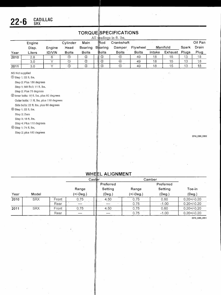
99 c CADILLAC
££"
Year
2010
2011
U SRX
Engine
Disp.
Liters
2.8
3.0
3.0
Engine
IDA/IN
6
Y
Y
Cylinder
Head
Bolts
©
©
©
TORQUE
All*
Main
Bearing
Bolts
©
©
©
B
.
SPECIFICATIONS
;adings in ft. Ibs.
^od Crankshaft
taring Damper
$olts Bolts
|© ©
© ©
(I © ©
NS Not supplied
©Step 1:22 ft. Ibs.
Step 2: Plus 150 degrees
Step 1:M8 Bolt: 11 ft. Ibs.
Stpn 9- Pln<; 75 dpnrpps
Flywheel Manifold
Oil Pan
Spark Drain
Bolts Intake Exhaust Plugs Plug
49 18
49 18
49 18
5 13 18
5 13 18
5 13 18
@ Inner bolts: 15 ft. Ibs. plus 80 degrees
Outer bolts: 11 ft. Ibs. plus 110 degrees
Side bolts: 22 ft. Ibs. plus 60 degrees
©Step 1:22ft. Ibs.
Step 2: Zero
Step 3:18 ft. Ibs.
Step 4: Plus 110 degrees
©Step 1:74 ft. Ibs.
Step 2: plus 150 degrees
25742_CSRX_C0010
WHEEL ALIGNMENT
Cast Camber
Range
Year Model (+/-Deg.j
2010
2011
SRX
SRX
Front
Rear
Front
Rear
0.75
—
0.75
—
[
Preferred Preferred
Setting Range Setting Toe-in
(Deg.) (+/-Deg.) (Deg.) (Deg.)
4.50
—
4.50
—
0.75
0.75
0.75
0.75
0.60
-1.00
0.60
-1.00
0.20+/-0.20
0.20+/-0.20
0.20+/-0.20
0.20+/-0.20
25742_CSRX_C0011
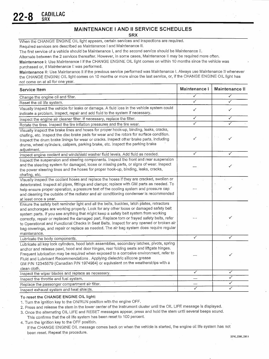
22-8
CADILLAC
SRX
MAINTENANCE I AND II SERVICE SCHEDULES
SRX
When the CHANGE ENGINE OIL light appears, certain services and inspections are required.
Required services are described as Maintenance I and Maintenance II.
The first service of a vehicle should be Maintenance I, and the second service should be Maintenance II.
Alternate between the 2 services thereafter. However, in some cases, Maintenance II may be required more often.
Maintenance I: Use Maintenance I if the CHANGE ENGINE OIL light comes on within 10 months since the vehicle was
purchased or, if Maintenance II was performed.
Maintenance II: Use Maintenance II if the previous service performed was Maintenance I. Always use Maintenance II whenever
the CHANGE ENGINE OIL light comes on 10 months or more since the last service, or, if the CHANGE ENGINE OIL light has
not come on at all for one year.
Service Item
Change the engine oil and filter.
Reset the oil life system.
Visually inspect the vehicle for leaks or damage. A fluid loss in the vehicle system could
indicate a problem. Inspect, repair and add fluid to the system if necessary.
Inspect the engine air cleaner filter. If necessary, replace the filter.
Rotate the tires. Inspect the tire inflation pressures and the tire wear.
Visually inspect the brake lines and hoses for proper hook-up, binding, leaks, cracks,
chafing, etc. Inspect the disc brake pads for wear and the rotors for surface condition.
Inspect the drum, brake linings for wear or cracks. Inspect other brake parts, including
drums, wheel cylinders, calipers, parking brake, etc. Inspect the parking brake
adjustment.
Inspect engine coolant and windshield washer fluid levels. Add fluid as needed.
Inspect the suspension and steering components. Inspect the front and rear suspension
and the steering system for damaged, loose or missing parts, or signs of wear. Inspect
the power steering lines and the hoses for proper hook-up, binding, leaks, cracks,
chafing, etc.
Visually inspect the coolant hoses and replace the hoses if they are cracked, swollen or
deteriorated. Inspect all pipes, fittings and clamps; replace with GM parts as needed. To
help ensure proper operation, a pressure test of the cooling system and pressure cap
and cleaning the outside of the radiator and air conditioning condenser is recommended
at least once a year.
Ensure the safety belt reminder light and all the belts, buckles, latch plates, retractors
and anchorages are working properly. Look for any other loose or damaged safety belt
system parts. If you see anything that might keep a safety belt system from working
correctly, repair or replaced, the damaged part. Replace torn or frayed safety belts, refer
to Operational and Functional Checks in Seat Belts. Inspect for any opened or broken air
bag coverings, and repair or replace as needed. The air bag system does require regular
maintenance.
Lubricate the body components.
Lubricate all key lock cylinders, hood latch assemblies, secondary latches, pivots, spring
anchor and release pawl, hood and door hinges, rear folding seats and liftgate hinges.
Frequent lubrication may be required when exposed to a corrosive environment, refer to
Fluid and Lubricant Recommendations . Applying dielectric silicone grease
GM P/N 12345579 (Canadian P/N 1974984) or equivalent on the weatherstrips with a
clean cloth.
Inspect the wiper blades and replace as necessary.
Inspect the throttle and fuel system.
Replace the passenger compartment air filter. ' . • '
Inspect exhaust system and heat shields.
Maintenance I
S
V
V
•/
•/
V
•/
—
—
—
•/
—
•/
—
—
s
Maintenance II
S
•s
V
s
s
•/
•S
-/
V
V
•/
V
V
•S
s
V
To reset the CHANGE ENGINE OIL light:
1. Turn the ignition key to the ON/RUN position with the engine OFF.
2. Press and release the stem in the lower center of the instrument cluster until the OIL LIFE message is displayed.
3. Once the alternating OIL LIFE and RESET messages appear, press and hold the stem until several beeps sound.
This confirms that the oil life system has been reset to 100 percent.
4. Turn the ignition key to the OFF position.
If the CHANGE ENGINE OIL message comes back on when the vehicle is started, the engine oil life system has not
been reset. Repeat the procedure.
25742_CSRX_C0014
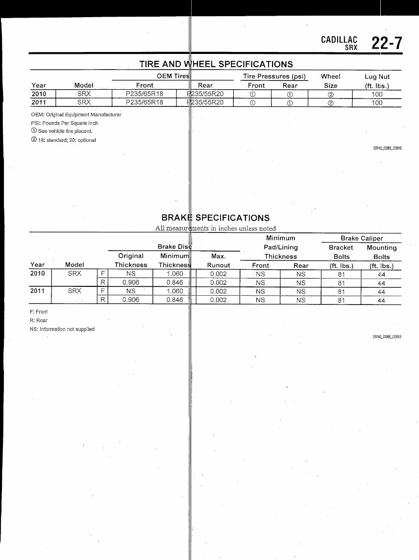
^^^^^^^^^^^^^^^^^^-^—
TIRE AND V
OEM Tires
Year Model Front
2010 SRX P235/65R18 f}
2011 SRX P235/65R18 ff
OEM: Original Equipment Manufacturer
PSl: Pounds Per Square Inch
© See vehicle tire placard.
@ 1 8: standard; 20: optional
BRAKl
All measun
Brake Dis
Original Minimum
Year Model Thickness Thickness
2010 SRX F NS 1.060
R 0.906 0.846
2011 SRX F NS 1.060
R 0.906 0.846
F: Front
R: Rear
NS: Information not supplied
CADILLAC 99 7
SRX "" /
HEEL SPECIFICATIONS
Tire Pressures (psi) Wheel Lug Nut
Rear Front Rear Size (ft. Ibs.)
235/55R20 © © © 100
235/55R20 © © © 100
25742_CSRX_C0012
i SPECIFICATIONS
merits in inches unless noted
i Minimum Brake Caliper
Pad/Lining Bracket Mounting
Max. Thickness Bolts Bolts
Runout Front Rear (ft. Ibs.) (ft. Ibs.)
0.002 -NS NS 81 44
0.002 NS NS 81 44
0.002 NS NS 81 44
; 0.002 NS NS 81 44
2574!LCSRX_C0013
CADILLAC
SRX
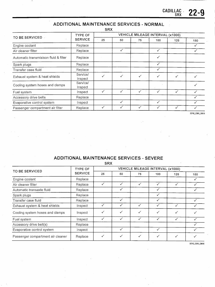
22-9
ADDITIONAL MAINTENANCE SERVICES - NORMAL
SRX
TO BE SERVICED
Engine coolant
Air cleaner filter
Automatic transmisison fluid & filter
Spark plugs
Transfer case fluid
Exhaust system & heat shields
Cooling system hoses and clamps
Fuel system
Accessory drive belts
Evaporative control system
Passenger compartment air filter
TYPE OF
SERVICE
Replace
Replace
Replace
Replace
Replace
Service/
Inspect
Service/
Inspect
Inspect
Replace
Inspect
Replace
VEHICLE MILEAGE INTERVAL (x1 000)
25
•/
S
•/
50
s
•/
s
•/
•/
75
•/
S •
•/
100
^
•/
s
s
s
•/
s
V
125
V
•/
•/
150
Y
S
V
S
•/
S
S
•/
25742_CSRX_C0015
ADDITIONAL MAINTENANCE SERVICES - SEVERE
SRX
TO BE SERVICED
Engine coolant
Air cleaner filter
Automatic transaxle fluid
Spark plugs
Transfer case fluid
Exhaust system & heat shields
Cooling system hoses and clamps
Fuel system
Accessory drive belt(s)
Evaporative control system
Passenger compartment air cleaner
TYPE OF
SERVICE
Replace
Replace
Replace
Replace
Replace
Inspect
Inspect
Inspect
Replace
Inspect
Replace
VEHICLE MILEAGE INTERVAL (xlOOO)
25
•/
S
•/
•s
•/
50
•/
S
•/
V
•/
•/
•/
s
75
S
S
-/
S
•/
100
•/
•/
•/
•/
s
s
•/
s
•/
125
V
V
•/
S
•/
150
•/
V
V
s
•/
s
s
•s
•/
•s
25742_CSRX_C0016
22-10 CADILLAC
SRX
PRECAUTIONS
Before servicing any vehicle, please be
sure to read all of the following precautions,
which deal with personal safety, prevention
of component damage, and important points
to take into consideration when servicing a
motor vehicle:
• Never open, service or drain the radia-
tor, or cooling system when the engine is
hot; serious burns can occur from the steam
and hot coolant.
• Observe all applicable safety precau-
tions when working around fuel. Whenever
servicing the fuel system, always work in a
well-ventilated area. Do not allow fuel spray
or vapors to come in contact with a spark,
open flame, or excessive heat (a hot drop
light, for example). Keep a dry chemical fire
extinguisher near the work area. Always
keep fuel in a container specifically
designed for fuel storage; also, always
properly seal fuel containers to avoid the
possibility of fire or explosion. Refer to the
additional fuel system precautions later in
this section.
• Fuel injection systems often remain
pressurized, even after the engine has been
turned OFF. The fuel system pressure must,
be relieved before disconnecting any fuel
lines. Failure to do so may result in fire
and/or personal injury.
• Brake fluid often contains polyglycol
ethers and polyglycols. Avoid contact with
the eyes and wash your hands thoroughly
after handling brake fluid. If you do get
brake fluid in your eyes, flush your eyes
with clean, running water for 15 minutes.
If eye irritation persists, or if you have taken
GENERAL INFORMATION
PRECAUTIONS
• Certain components within the ABS '
system are not intended to be serviced or
repaired individually.
• Do not use rubber hoses or other parts
not specifically specified for and ABS sys-
tem. When using repair kits, replace all
parts included in the kit. Partial or incorrect
repair may lead to functional problems and
require the replacement of components.
• Lubricate rubber parts with clean,
fresh brake fluid to ease assembly. Do not
use shop air to clean parts; damage to rub-
ber components may result.
• Use only DOT 3 brake fluid from an
unopened container.
• If any hydraulic component or line is
:e n
brake fluid in]
medical assis'
• The EP/^
with used enc
of skin disord
should make!
exposure to u
gloves slioulc
Wash your ha
skin areas as
sure to used e
waterless nan
• All new
with an air ba
a Supplement
Supplemental'
tern. The syst
performing se
components,
panel compor
Failure to
dures could re
deployment,
unnecessary
• Always v
working with,
When carrying a
sure the bag
away from yoi
deployed air
face the bag a
from the surfa
motion of the
deployed. Refe
system precai
• Clean, h
sealed contair
rnally, IMMEDIATELY seek
nee.
warns that prolonged contact
ne oil may cause a number
rs, including cancer. You
very effort to minimize your
ed engine oil. Protective
be worn when changing oil.
ds and any other exposed
oon as possible after expo-
igine oil. Soap and water, or
cleaner should be used,
ehicles are now equipped
system, often referred to as
Restraint System (SRS) or
nflatable Restraint (SIR) sys-
must be disabled before
vice on or around system
:eeririg column, instrument
fits, wiring and sensors.
N safety and disabling proce-
sult in accidental air bag
personal injury and
/stem repairs,
ear safety goggles when
r around, the air bag system.
non-deployed air bag, be
trim cover are pointed
• body. When placing anon-
ig on a work surface, always
d trim cover upward, away
e. This will reduce the
nodule if it is accidentally
'to the additional air bag
ions later in this section.
;h quality brake fluid from a
r is essential to the safe and
aid
proper operation of the brake system. You
should always buy the correct type of brake
fluid' for your vehicle. If the brake fluid
becomes contaminated, completely flush the
system with new fluid. Never reuse any
brake fluid. Any brake fluid that is removed
from the system should be discarded. Also,,
do not allow any brake fluid to come in con-
tact with a painted surface; it will damage
the paint.
• Never operate the engine without the
proper amount and type of engine oil; doing
so WILL result in severe engine damage.
• Timing belt maintenance is extremely
important. Many models utilize an
interference-type, non-freewheeling engine.
If the timing belt breaks, the valves in the
cylinder head may strike the pistons, caus-
ing potentially serious (also time-consum-
ing and expensive) engine damage. Refer to
the maintenance interval charts for therec-
ommended replacement interval for the tim-
• ing belt, and to the timing belt section for
belt replacement and inspection.
• Disconnecting the negative battery
cable on some vehicles may interfere with
the functions of the on-board computer sys-
tem^) and may require the computer to
undergo a relearning process once the
negative battery cable is reconnected.
• When servicing drum brakes, only dis-
assemble and assemble one side at a time,
leaving the remaining side intact for refer-
ence.
• .Only an MVAC-trained, EPA-certified
automotive technician should service the air
conditioning system or its components.
ANTI-LOCK BRAKE SYSTEM (A^S)
removed or re
bleed the entiij
• A clean r
clean the resei
before removing
amount of dirt
fice and impai
repairs
oughly cleane
to clean comp
components to
substance
includes used
• TheAntH
laced, it may be necessary to
system.
pair area is essential. Always
/oir and cap thoroughly
the cap. The slightest
n the fluid may plug an ori-
•the system function. Perform
after components have been thor-
use only denatured alcohol
nents. Do not allow ABS
come into contact with any
mineral oil; this
;hop rags.
.ock control unit is a micro-
processor simj ar to other computer units in
the vehicle. Erj ;ure that the ignition switch
is OFF before emoving or installing con-
troller harnessi s. Avoid static electricity dis-
charge at or ne.br the controller.
con aming
• If any arc welding is to be done on
the vehicle, the control unit should be
unplugged before welding operations
begin.
SPEED SENSORS
REMOVAL & INSTALLATION
Front
See Figure 1.
1. Before servicing the vehicle, refer to
the Precautions Section.
2. Raise and support the vehicle.
3. Remove the tire and wheel assembly.
4. Remove the wheel speed sensor bolt.
5. Clean the wheel speed sensor
mounting area on the suspension knuckle of
any accumulated dirt and debris.
You're Reading a Preview
What's Included?
Fast Download Speeds
Online & Offline Access
Access PDF Contents & Bookmarks
Full Search Facility
Print one or all pages of your manual
$33.99
Viewed 28 Times Today


Secure transaction
What's Included?
Fast Download Speeds
Online & Offline Access
Access PDF Contents & Bookmarks
Full Search Facility
Print one or all pages of your manual
$33.99
The SRX 2010-2011 Service Repair Manual covers a comprehensive range of repairs, including brakes, wiring, engine, and transmission. It is an invaluable resource for both professional mechanics and DIY enthusiasts.
By utilizing this manual, you can avoid expensive hourly labor costs and mark-up fees on parts. It enables you to take control of your car repairs and save money by purchasing your own parts.
Whether you are looking to perform routine maintenance or tackle more complex repairs, this manual provides the necessary guidance and instructions to empower you to make your own repairs.


