1990 Cadillac Brougham Service & Repair Manual Software
What's Included?
Lifetime Access
Fast Download Speeds
Online & Offline Access
Access PDF Contents & Bookmarks
Full Search Facility
Print one or all pages of your manual
1990 ENGINES 5.0L (307CI) V8 - VIN Y ENGINE IDENTIFICATION This 5.0L engine may be identified from the Vehicle Identification Number (VIN). The VIN is stamped on a plate, on top of the instrument panel. This plate is visible the through windshield. The VIN contains 17 characters. The 8th character of the VIN identifies the engine. The 10th character of the VIN identifies the model year (L = 1990) of the vehicle. All engines are stamped with an engine identification label. This engine identification label will identify the assembly plant, the month/date produced, and the engine type code. ENGINE IDENTIFICATION CODES ADJUSTMENTS VALVE ARRANGEMENT I-E-I-E-E-I-E-I (Front-to-rear, both banks). VALVE CLEARANCE ADJUSTMENT Valve clearance is nonadjustable. Tighten rocker arms to specifications. See TORQUE SPECIFICATIONS table at end of this article. TROUBLE SHOOTING REMOVAL & INSTALLATION NOTE: For engine repair procedures not covered in this article, see ENGINE OVERHAUL PROCEDURES - GENERAL INFORMATION article in the GENERAL INFORMATION section. Application Engine Code VIN Code 4-Bbl. LV2 Y NOTE: For reassembly reference, label all electrical connectors, vacuum hoses and fuel lines prior to removal. Match mark engine hood and all other major components prior to removal. NOTE: To trouble shoot mechanical engine components, see appropriate table in TROUBLE SHOOTING article in GENERAL INFORMATION.
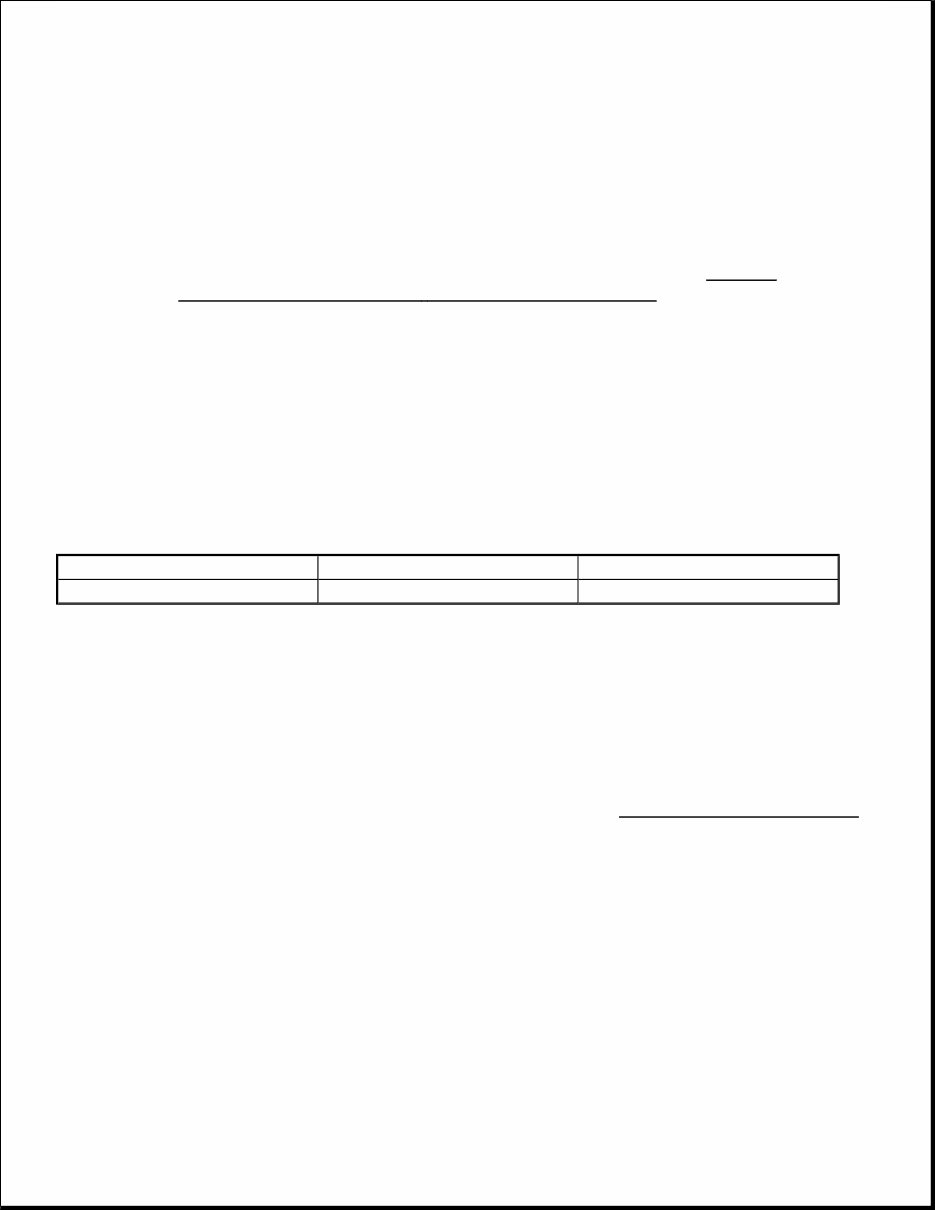
ENGINE Removal 1. Disconnect battery and remove air cleaner. Drain radiator. Disconnect radiator hoses and remove upper fan shroud. Remove fan assembly. Disconnect heater hoses at engine. 2. Remove power steering pump and lay aside. Remove A/C compressor and lay aside. Disconnect accelerator and throttle valve cable. Disconnect cooler lines at radiator (if equipped). Remove radiator. 3. Disconnect vacuum hoses. Disconnect Computer Command Control (CCC) wiring harness. Disconnect Air Injection Reaction (AIR) hose at pipe from converter. Remove washer bottle. Disconnect engine wiring harness at bulkhead. Disconnect necessary wires. Remove hood. 4. Remove distributor cap. Disconnect cruise control cable. Disconnect positive battery cable. Disconnect negative battery cable at A/C hose bracket and alternator bracket. Raise and support vehicle. 5. Remove crossover pipe and catalytic converter as an assembly. Remove flexplate cover. Remove torque converter bolts. Remove motor mount bolts. Disconnect fuel inlet hose at fuel pump. Disconnect torque converter clutch wiring at transmission. 6. Disconnect transmission cooler lines at clip on engine oil pan. Remove transmission-to-engine bolts. Lower vehicle. Support transmission. Install lifting device and remove engine. Installation To install, reverse removal procedure. Tighten bolts to specification. See TORQUE SPECIFICATIONS . With engine off, fill radiator until level is even with base of filler neck. Fill coolant recovery reservoir to COLD FILL mark. Install coolant recovery reservoir cap. Run engine until radiator inlet hose is hot. With engine at idle, add coolant to radiator until level is even with base of filler neck. Install cap. INTAKE MANIFOLD Removal 1. Disconnect battery negative cable and drain coolant. Remove air cleaner. Remove AIR crossover pipe. Disconnect upper radiator hose, thermostat by-pass hose and heater hose(s) at rear of manifold. Mark and disconnect fuel and vacuum lines. Disconnect linkage at carburetor. Mark and remove necessary electrical connectors. 2. Remove rear brace from alternator and A/C compressor. Remove EGR valve, idle load compensator and bracket assembly. Remove intake manifold bolts in reverse sequence of installation. See Fig. 1 . Remove intake manifold and gaskets. Clean surfaces thoroughly.
Fig. 1: Intake Manifold Sealing & Tightening Sequence Courtesy of GENERAL MOTORS CORP. Installation Apply Sealer (1050026) to both sides of intake manifold gasket at all port areas. Apply Sealer (1052915) to both ends of front and rear seals. See Fig. 1 . Lubricate intake bolts with engine oil. To complete installation, reverse removal procedure. Tighten bolts in sequence to specifications. See TORQUE SPECIFICATIONS . EXHAUST MANIFOLD Removal & Installation (Left) Disconnect negative battery cable. Remove air cleaner. Raise and support vehicle. Separate inlet pipe at exhaust manifold. Lower vehicle. Remove exhaust manifold heat shields. Remove lower alternator bracket. Remove exhaust manifold and gasket. To install, reverse removal procedure. Tighten bolts to specification. See TORQUE SPECIFICATIONS . Removal & Installation (Right)
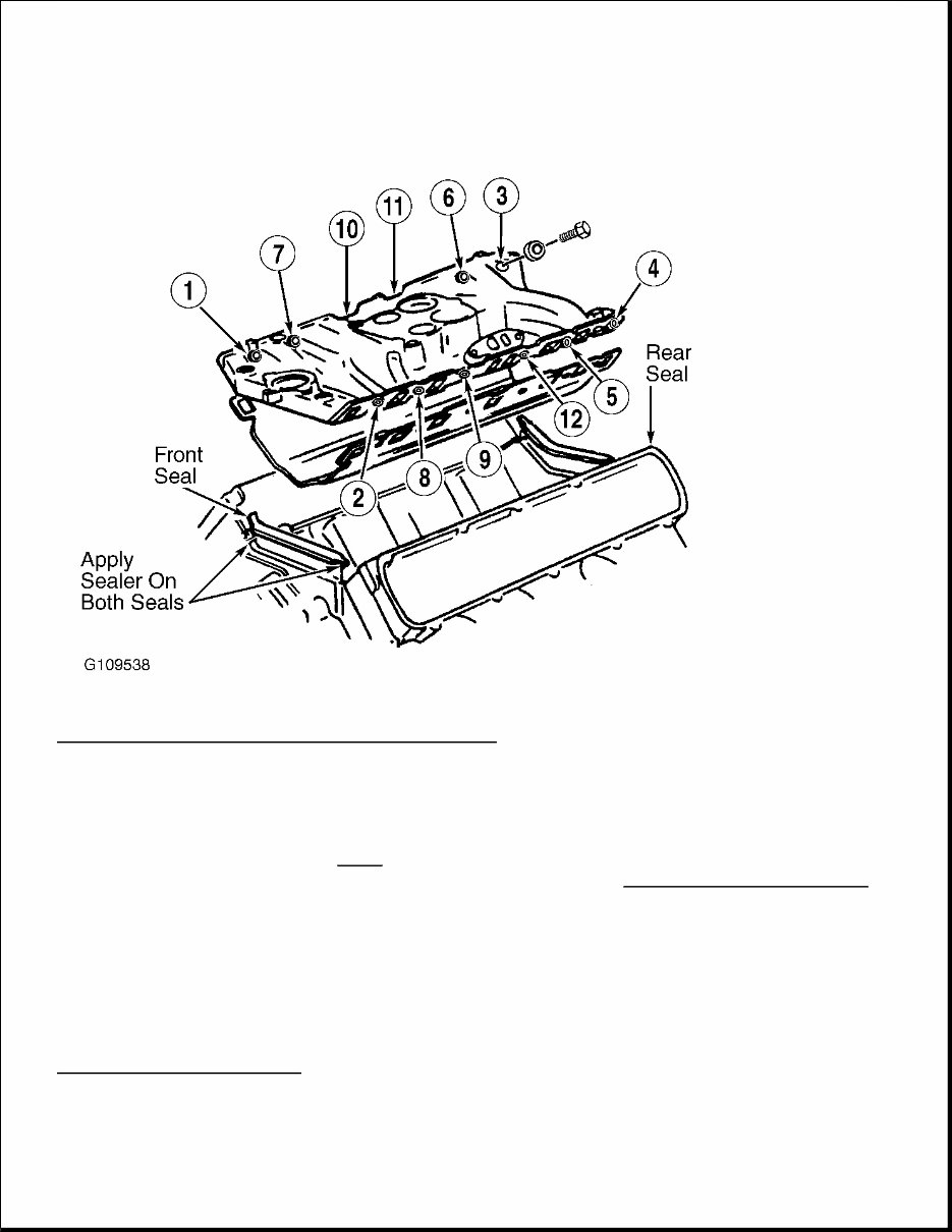
Disconnect negative battery cable. Remove air cleaner. Disconnect O2 sensor wire. Raise vehicle. Remove crossover AIR pipe. Separate inlet pipe at exhaust manifold. Remove right front tire, oil filter adapter, gasket, exhaust manifold and gasket. To install, reverse removal procedure. Tighten bolts to specification. See TORQUE SPECIFICATIONS . VALVE COVERS Removal 1. Disconnect negative battery cable. On left side, mark and remove spark plug wires and necessary electrical connectors. Remove anti-dieseling solenoid. Remove alternator belt and rear brace. Loosen exhaust manifold upper heat shield only. Remove EGR valve and oil dipstick. 2. On right side, reposition and move heater hoses. Remove PCV valve and hose. Disconnect anti-dieseling solenoid vacuum hoses. Disconnect AIR, O2 sensor and anti-dieseling solenoid. Disconnect canister purge hose. Disconnect hoses to AIR switching valve and catalytic converter pipe. Remove AIR switching valve, AIR/AC belt, AIR pump pulley and A/C compressor rear brace. 3. On both sides, remove valve cover bolts/nuts. Install Valve Cover Seal Breaker (BT-8315 or J-34144) midway between the ends of valve cover, on upper side. See Fig. 2 . Tighten screw on seal breaker until a load is applied to valve cover. Place cloth on valve cover and strike with rubber mallet. If cloth is not used to absorb mallet, valve cover will be damaged. Fig. 2: Removing Valve Cover With Special Tool Courtesy of GENERAL MOTORS CORP. Installation
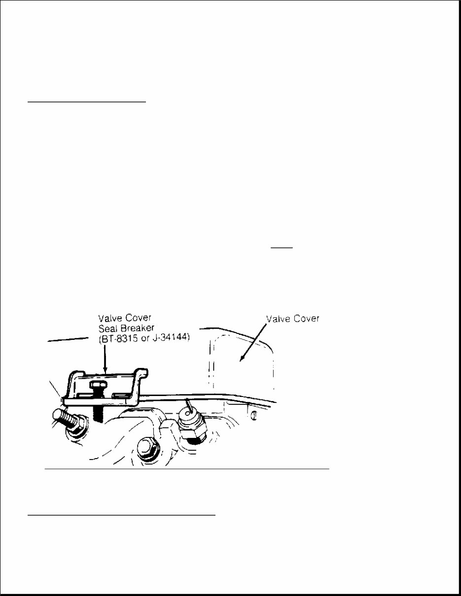
Clean sealing mating surfaces. Apply 1/4" bead of Sealer (1052915) to valve cover. Sealer should be on inner side of bolt holes. Install and tighten valve cover. To complete installation, reverse removal procedure. CYLINDER HEAD Removal 1. Disconnect battery negative cable and drain coolant. Remove intake manifold, exhaust manifold(s) and valve cover(s) as previously described. Disconnect ground cable to cowl. Remove accessories and brackets as necessary. 2. Remove rocker arm bolts, rocker arm pivots, rocker arms and push rods. Note location for installation. If rear cylinder head bolts and/or push rods can not be removed, remove them with cylinder head. Remove cylinder head bolts, cylinder head and gasket. Inspection 1. Clean gasket surfaces. Check head and block gasket surface for warpage. Replace cylinder head if more than .006" (.15 mm) needs to be machined from original surface. Check for cracks and replace as necessary. Check head bolts for damage and stretching. Replace as necessary. Tap threads on bolts and in block. 2. Clean push rods in solvent and blow out oil passage with compressed air. Check ends of push rod for excessive wear and runout. If runout exceeds .015" (.38 mm), replace push rod. Apply Molykote to rocker arm contact points and push rod ends during installation. Installation Properly install head gasket onto dowel pins. Install cylinder head over dowel pins and gasket. Dip head bolt threads in engine oil and allow to drain. Install head bolts. Tighten in sequence to specifications. See TORQUE SPECIFICATIONS table at end of this article. To complete installation, reverse removal procedure. NOTE: Check and record compression before removing cylinder head. Ensure components are installed to original position and location. NOTE: DO NOT use any sealant on head gaskets.
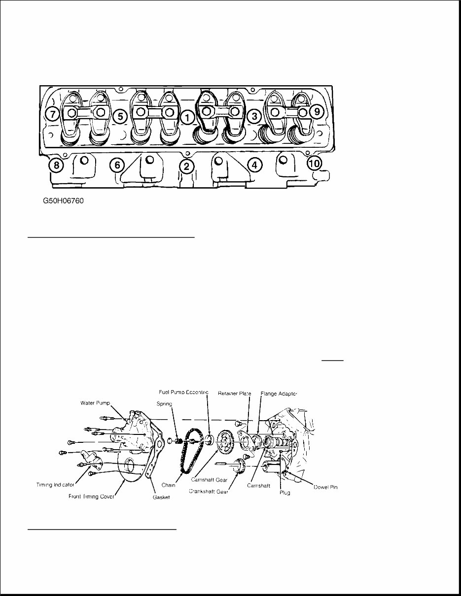
Fig. 3: Cylinder Head Tightening Sequence Courtesy of GENERAL MOTORS CORP. FRONT TIMING COVER & SEAL Removal 1. Disconnect negative battery cable. Drain cooling system and remove radiator. Remove A/C and power steering assembly with hoses attached and set aside. Remove cooling fan and pulley. Remove crankshaft balancer hub (damper) with Balancer Puller (J-8614). 2. Remove front timing cover seal, if cover does not require removal, with an inside 3-finger type puller. Remove fuel pump (if removing cover). Remove front timing cover retaining bolts/studs. Remove timing indicator. Remove front timing cover and water pump as an assembly. See Fig. 4 . Remove dowel pins. Fig. 4: Exploded View of Engine Front Courtesy of GENERAL MOTORS CORP.
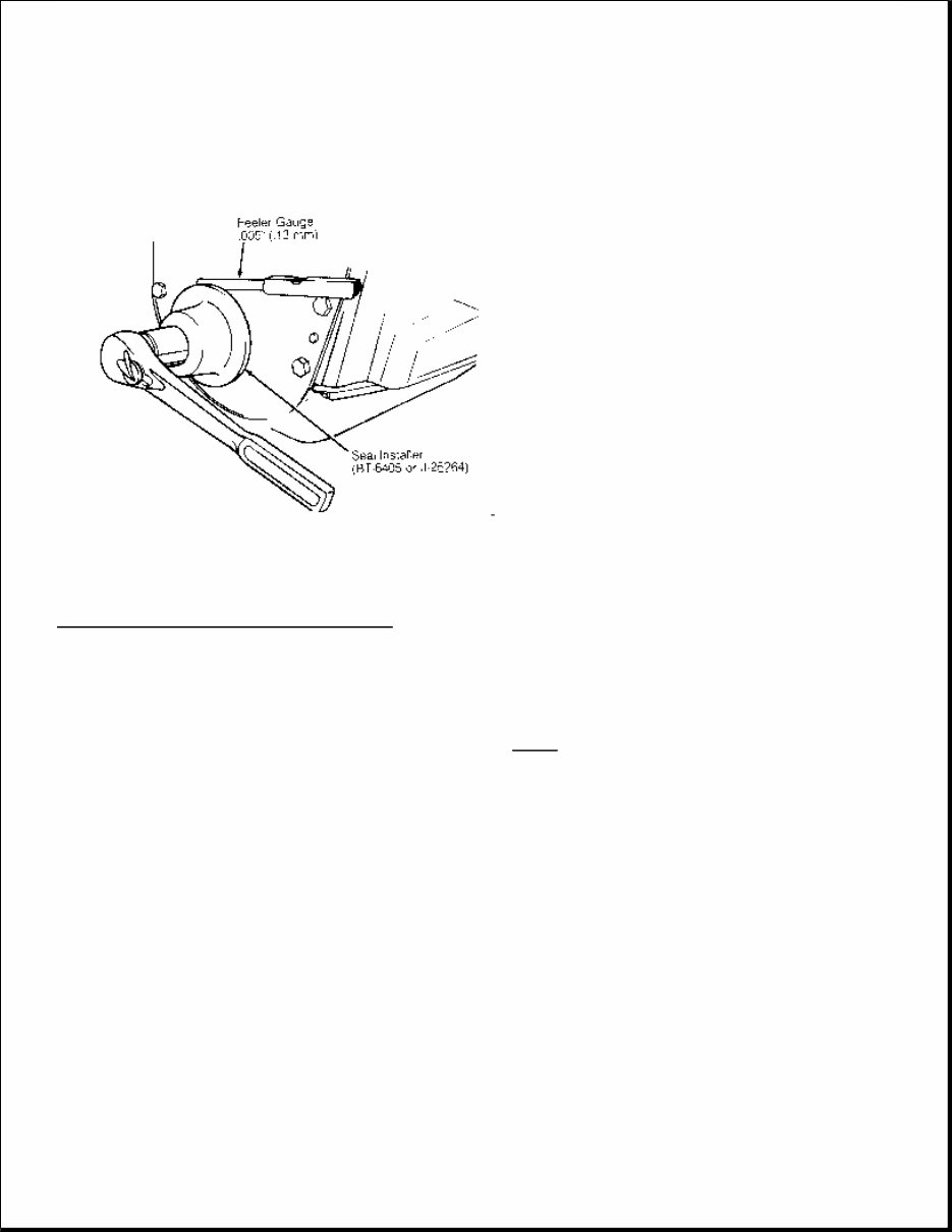
Fig. 5: Installing Front Timing Cover Seal Courtesy of GENERAL MOTORS CORP. Installation 1. If front timing cover was not removed, install seal with Seal Installer (BT-6405 or J-25264) until proper clearance between installer and cover is achieved. See Fig. 5 . 2. If front timing cover was removed, trim protruding oil pan gasket material flush with engine. Apply Sealer (1050026) around coolant holes in new cover gasket and place gasket on block. Trim 1/8" from each end of cover-to-oil pan saddle seal. 3. Apply Sealer (1052915) to joining corners of engine block, oil pan and saddle seal. Glue oil pan saddle seals in place on timing cover. Position bottom of cover with saddle seal to oil pan. Press down to compress saddle seal. Using a small screwdriver, guide saddle seal edges into cavity while installing timing cover. 4. Oil timing cover retaining bolts and install 2 bolts finger tight. Install dowel pins, chamfer end first. To complete installation, reverse removal procedure.
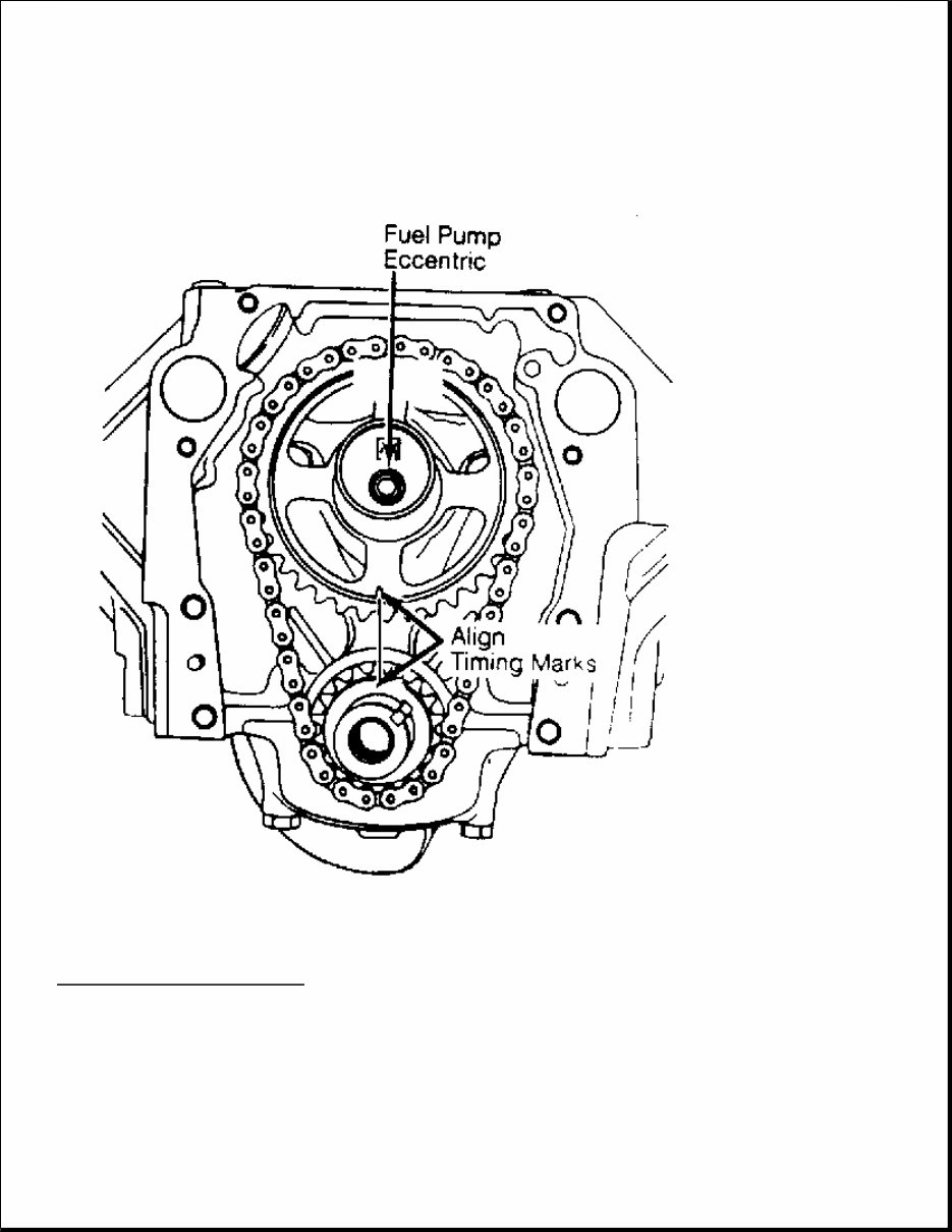
Fig. 6: Timing Gear Alignment Courtesy of GENERAL MOTORS CORP. TIMING CHAIN & GEARS Removal & Installation 1. Remove front timing cover. See FRONT TIMING COVER & SEAL. Remove fuel pump eccentric. See
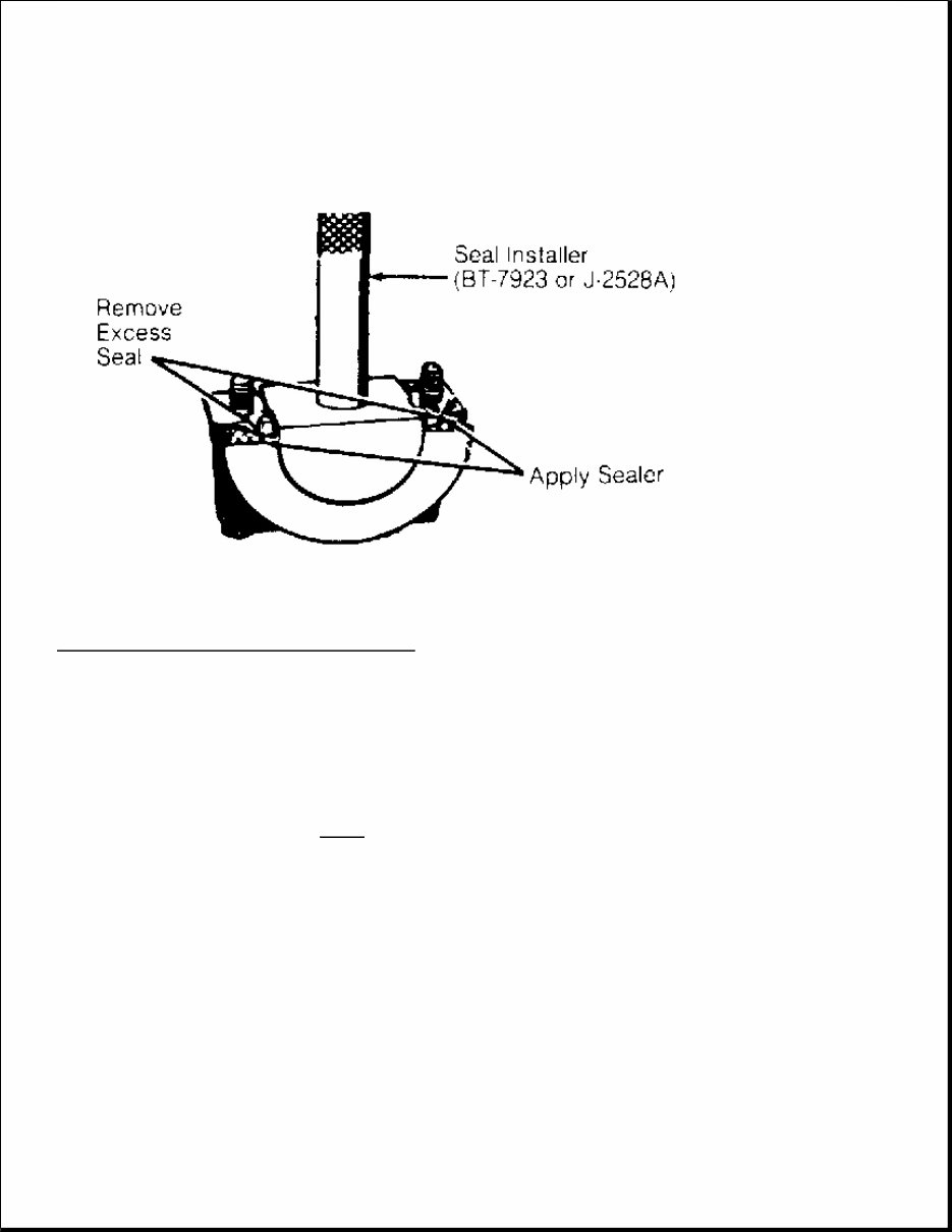
Fig. 4 . Align timing marks on camshaft and crankshaft gears. See Fig. 6 . 2. Remove camshaft gear and chain as an assembly. Remove crankshaft key BEFORE attempting to remove crankshaft gear. Remove crankshaft gear with a puller (if replacing). To install, reverse removal procedure. With camshaft and crankshaft gear marks aligned, No. 6 cylinder is at TDC on compression stroke. See Fig. 6 . CAMSHAFT Removal & Installation 1. Remove timing chain and gears. See TIMING CHAIN & GEARS. Discharge A/C system and remove A/C condenser. Remove distributor cap with plug wires. Remove intake manifold and valve covers. See INTAKE MANIFOLD and VALVE COVERS. Mark and remove rocker arms, pushrods and lifters. Note location for installation. 2. Remove camshaft retainer plate. Remove flange adapter. See Fig. 4 . Pull camshaft out of engine. If installing new camshaft add EP Lubricant (1051396) to engine oil. To install, reverse removal procedure. Use EP lubricant on components during installation. Inspection Check bearing and lobe surfaces for wear, galling, gouges and discoloration (overheating). Measure lobe lift, bearing journal runout and diameter with camshaft in "V" block. Replace as necessary. See ENGINE SPECIFICATIONS table at end of article. REAR MAIN BEARING OIL SEAL Removal & Installation Rear main bearing oil seal is a 2 piece rope seal. The lower portion may be replaced with engine in vehicle. Crankshaft removal is required for replacing upper portion. Use Seal Installer (J-2528A or BT-7923) to install seal. Cut excess seal material flush. Apply Sealer (1050026) to the main bearing cap as shown. See Fig. 7 . NOTE: Engine must be removed to install camshaft bearings. Ensure oil holes in bearings and block are aligned.
Fig. 7: Installing Rear Main Bearing Oil Seal Courtesy of GENERAL MOTORS CORP. WATER PUMP Removal & Installation Disconnect negative battery. Drain cooling system. Remove necessary accessories and brackets. Remove fan and pulley. Disconnect lower radiator hose and heater hoses from water pump. Remove water pump retaining bolts and remove water pump. See Fig. 4 . Apply Sealer (10500026) to new gasket and place on water pump. To complete installation, reverse removal procedure. OIL PAN 1. Disconnect negative battery cable. Remove air cleaner, fan shroud and distributor cap. Raise vehicle and drain crankcase. Disconnect exhaust pipe at manifold, Air Injection Reaction (AIR) pipe clamp and catalytic converter hanger bolts. 2. Remove front starter brace, starter and flexplate access cover. On models with M/T, it may be necessary to remove oil filter for access to flywheel cover bolts. 3. Remove engine mount through bolts and oil pan bolts. Raise engine and lower pan. Position front crankshaft throw and/or counterweights as to clear oil pan. Remove oil pan. NOTE: For further information on cooling systems, see ENGINE COOLING.
If you are in need of a repair manual for your 1990 Cadillac Brougham, look no further. Our comprehensive repair manual software is designed to provide all the necessary service and repair information for professional mechanics and DIY enthusiasts alike.
In the past, obtaining a traditional service manual in book format was not only costly but also inconvenient. Our repair manual software offers a more affordable and accessible alternative, allowing you to access the same valuable information in a digital format.
Whether you are looking to address brake issues, replace suspension components, troubleshoot engine problems, or perform standard maintenance, our repair manual software for the Cadillac Brougham has you covered. It encompasses a wide range of service information, including brakes, engine, suspension, steering, drivetrain, electrical systems, heating, and air conditioning.
By utilizing this repair manual software, you can save a significant amount of money on vehicle maintenance and repairs. Professional mechanic services can be costly, making a DIY approach with our comprehensive manual a cost-effective solution.
Our repair manual software is designed for ease of use and compatibility with Windows, Mac computers, smartphones, and tablets, ensuring convenient access to the manual for your 1990 Cadillac Brougham.
Recently Viewed
5,521,897Happy Clients
2,594,462eManuals
1,120,453Trusted Sellers
15Years in Business
Price:
Actual Price:
1990 Cadillac Brougham Service & Repair Manual Software