1986-1993 Cadillac Allante Service & Repair Manual
What's Included?
Lifetime Access
Fast Download Speeds
Online & Offline Access
Access PDF Contents & Bookmarks
Full Search Facility
Print one or all pages of your manual
1986-1993 CADILLAC ALLANTE SERVICE AND REPAIR MANUAL
RESTRAINT SYSTEMS Air Bags - Allante DESCRIPTION & OPERATION SUPPLEMENTAL INFLATABLE RESTRAINT (SIR) SYSTEM Supplemental Inflatable Restraint (SIR) system is designed to protect the driver in a frontal collision. The air bag will deploy only upon frontal or near frontal impact of no more than 30 degrees off the centerline of the vehicle. The system is not designed to deploy in rear impacts, side impacts or rollover. A frontal impact of sufficient severity (comparable to a collision into a solid wall at approximately 14 MPH or more) will cause the sensors in the vehicle to detect this sudden deceleration. These sensors, in turn, trigger the inflator module. DIAGNOSTIC ENERGY RESERVE MODULE (DERM) The Diagnostic Energy Reserve Module (DERM) maintains a 36-Volt Loop Reserve (36VLR) energy supply to provide deployment energy for approximately 10-14 minutes if voltage is low or lost in an accident. In addition, the DERM performs diagnostic monitoring of all system components, stores both current and past SIR system fault code information, warns driver of SIR system faults by controlling INFLATABLE RESTRAINT indicator light and records SIR system status during a vehicle accident. The DERM is connected to the SIR harness by a 24-pin connector. The harness connector uses gold-plated terminals and a gold-plated shorting bar in the contact area. The DERM connector also has a gold-plated shorting bar to connect INFLATABLE RESTRAINT indicator input to ground when the DERM connector is disconnected. With the DERM disconnected, the INFLATABLE RESTRAINT indicator remains on when ignition switch is turned to RUN or START positions. The DERM is located under the instrument panel. INFLATABLE RESTRAINT INDICATOR LIGHT When ignition switch is in RUN or START position, battery voltage is applied to the INFLATABLE RESTRAINT indicator light. The Diagnostic Energy Reserve Module (DERM) illuminates the light by providing a ground to a lamp driver. The INFLATABLE RESTRAINT indicator light verifies bulb and DERM operation by flashing 7-9 times when the ignition is first turned on, warning the driver of SIR electrical system faults which could potentially affect the operation of the SIR system. In addition, on vehicles without on-board diagnosis, the light provides diagnostic information by flashing fault codes when the flash code diagnostic mode is entered. The INFLATABLE RESTRAINT indicator light is the key to driver notification of SIR system faults. ARMING SENSOR The arming sensor is a protective switch located in the power feed side (positive side) of the deployment loop. It is calibrated to close at low-level velocity changes (lower than discriminating sensors). This ensures inflator WARNING: To avoid injury from accidental air bag deployment, read and carefully follow all WARNINGS and SERVICE PRECAUTIONS.
module is connected directly to the 36-Volt Loop Reserve (36VLR) output of the Diagnostic Energy Reserve Module (DERM) and ignition voltage when either discriminating sensor closes. The arming sensor consists of a sensing element, normally open switch contacts, a diagnostic resistor and 2 diodes. The sensing element closes the normally open switch contacts when the velocity of the vehicle changes at a rate indicating potential need for deployment. The diagnostic resistor is connected parallel with the normally open switch contacts and allows for a small amount of current flow through the deployment loop during normal non-deployment conditions. This small current flow results in voltage drops across each component within the loop. The DERM monitors these voltage drops to detect circuit or component faults. The 2 diodes provide isolation between the 36VLR output of the DERM and ignition voltage. In some vehicles, the arming sensor is combined with the passenger compartment discriminating sensor. The arming sensor is located under the center of the instrument panel/console area of the vehicle. DISCRIMINATING SENSORS There are 2 discriminating sensors in the SIR system. Some vehicles have 2 forward discriminating sensors, while other vehicles have one forward discriminating sensor and a passenger compartment discriminating sensor. The forward discriminating sensor(s) is located on the radiator support brace. The passenger compartment discriminating sensor is located under the center of the instrument panel/console area or under the front passenger seat. In some vehicles, the passenger compartment discriminating sensor is combined with the arming sensor. Discriminating sensors are wired in parallel on the ground side of the deployment loop. These sensors are calibrated to close when deceleration velocity changes are severe enough to warrant deployment. The sensors consist of a sensing element, normally open switch contacts and a diagnostic resistor. The sensing element closes the normally open switch contacts when the vehicle velocity changes are severe enough to warrant deployment. A diagnostic resistor is connected parallel with the normally open switch contacts within each of the sensors. These parallel resistors supply the ground path for the current passing through the deployment loop during normal non-deployment conditions. This small current flow results in a voltage drop across each component within the loop. The DERM monitors these voltage drops to detect circuit or component faults. SIR COIL ASSEMBLY The SIR coil assembly consists of 2 current-carrying coils. It is installed in the steering column and allows rotation of the steering wheel while maintaining continuous (directly wired) contact of the deployment loop through the inflator module. The SIR system does not use slip rings to transmit current from the column to the steering wheel. Gold-plated terminals and shorting bar are used on the coil assembly lower steering column Yellow connector. The shorting bar shorts the circuits to the main coil and inflator module when the lower steering column connector is disconnected. This shorts the circuit to the inflator module, preventing unwanted deployment of the air bag when servicing the steering column or other SIR components. INFLATOR MODULE
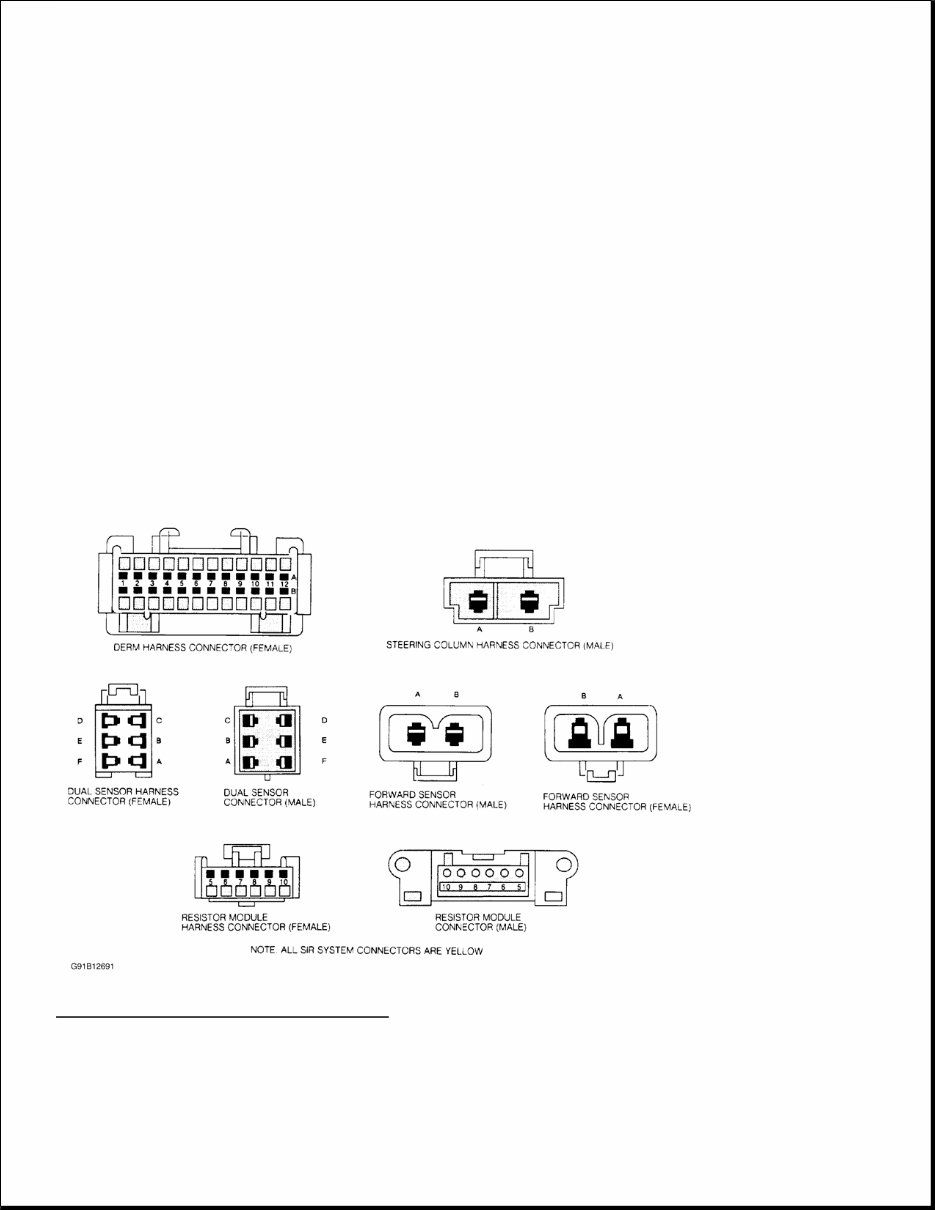
When the vehicle is in an accident of sufficient force to simultaneously close the arming sensor and at least one discriminating sensor, nitrogen gas inflates the air bag packed inside the steering wheel hub. The air bag inflates and deploys in less than 1/20 of a second. As the driver contacts the air bag, the gas is vented and deflation occurs. RESISTOR MODULE The resistor module is located in the SIR harness between the inflator module and the Diagnostic Energy Reserve Module (DERM). The resistor module allows the DERM to monitor the deployment loop for faults and to detect when a deployment has occurred. The resistors in the resistor module are balanced with the resistors on the arming and discriminating sensors to allow the DERM to monitor the voltage drops across the components of the deployment loop. Faults are detected during normal non-deployment conditions by monitoring these voltages. On some vehicles, the resistor module is mounted on the DERM. CONNECTOR IDENTIFICATION Fig. 1: SIR Wiring Connectors Face Views Courtesy of GENERAL MOTORS CORP. SERVICE PRECAUTIONS
Disable air bag system before servicing any air bag system or steering column component. Failure to do this could result in accidental air bag deployment and possible personal injury. See DISABLING & ACTIVATING AIR BAG SYSTEM . After an accident, all SIR components, including harness and brackets, must be inspected. If any components are damaged or bent, they must be replaced, even if a deployment did not occur. Check steering column, knee bolster, instrument panel steering column reinforcement plate and lower brace for damage. DO NOT service resistor module, inflator module, coil assembly, discriminating sensors, arming sensor or Diagnostic Energy Reserve Module (DERM). If these components are damaged or defective, replacement is necessary. After repairs, turn ignition on from passenger side of vehicle in case of accidental air bag deployment. Ensure INFLATABLE RESTRAINT light is working properly and no system faults are indicated. See SYSTEM OPERATION CHECK under DIAGNOSIS & TESTING. Always wear safety glasses when servicing or handling an air bag. Air bag module must be stored in its original special container until used for service. It must be stored in a clean, dry place, away from sources of extreme heat, sparks or high electrical energy. When placing a live air bag module on a bench or other surface, always face air bag and trim cover up, away from surface. This will reduce motion of module if accidentally deployed. After deployment, air bag surface may contain deposits of sodium hydroxide, which can irritate skin. Always wear safety glasses, rubber gloves and long-sleeved shirt during clean- up, and wash hands using mild soap and water. Follow correct disposal procedures. See DISPOSAL PROCEDURES . At no time should any electrical source be allowed near inflator on back of air bag module. When carrying a live air bag module, trim cover should be pointed away from your body to minimize injury in case of accidental deployment. DO NOT probe a wire through insulator; this will damage it and eventually cause failure due to corrosion. Coil assembly must be replaced whenever air bag deploys. When performing electrical tests, prevent accidental shorting of terminals. Such mistakes can damage fuses or components and may cause a second fault code to set, making diagnosis of original problem more difficult. When using diagnostic charts to diagnose air bag system, under no circumstances should a volt/ohmmeter, test light or any type of electrical equipment not specified by manufacturer be used. See SPECIAL TOOLS . If air bag system is not fully functional for any reason, vehicle should not be driven until system is repaired. DO NOT remove bulbs, modules, sensors or other components or in any way disable system from operating normally. If air bag system is not functional, park vehicle until repairs can be made. SPECIAL TOOLS To avoid deployment when working on SIR system, DO NOT use electrical test equipment such as test lights, battery or A/C-powered volt/ohmmeter or any type of electrical equipment not specified by manufacturer. See SIR RECOMMENDED TOOL table. NOTE: These precautions should be observed when working with air bag systems:
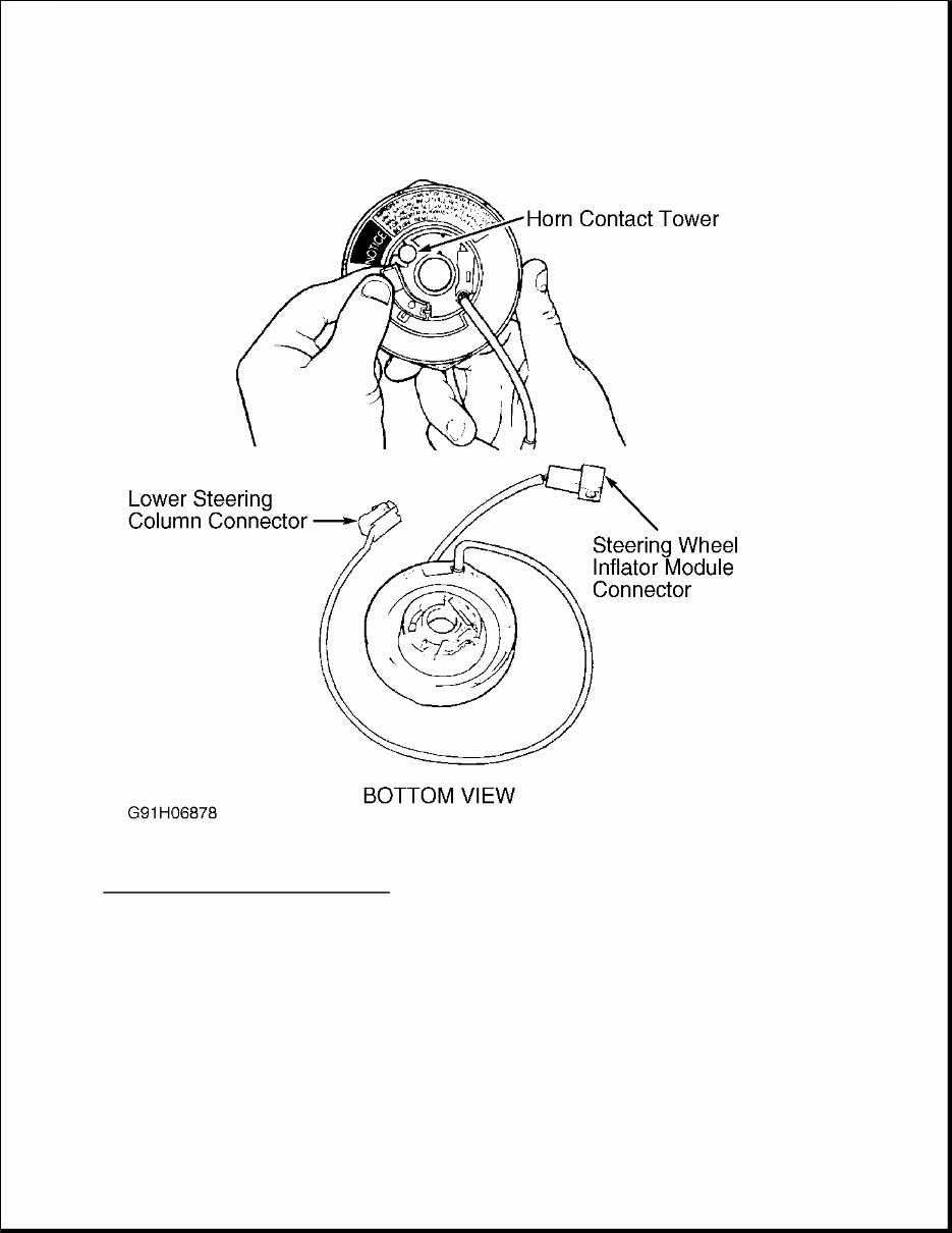
SIR RECOMMENDED TOOL ADJUSTMENTS CENTERING COIL ASSEMBLY ADJUSTMENTS 1. If coil assembly has been removed from steering column and is being reinstalled, go to step 2). New coil assemblies are provided pre-centered and include a Blue plastic tab, which is snapped off once coil is installed. See Fig. 2 . Tool Name Tool Number Connector Test Adapter Kit J-35616 Digital Volt/Ohmmeter J-34029-A Inflator Module Load Tool J-37808 Wire Repair Kit J-38125-A
Fig. 2: Installing SIR Coil Assembly Courtesy of GENERAL MOTORS CORP. 2. Ensure front wheels face straight ahead when installing or removing a coil assembly. If coil is removed without wheels in straight-ahead position and steering wheel has not been moved, same coil can be reinstalled if coil hub also has not been rotated. 3. Hold coil assembly with clear bottom upward to see coil ribbon. Note there are 2 different styles of coil assemblies; one rotates clockwise and other rotates counterclockwise. 4. While holding coil assembly housing, depress spring lock and rotate hub in direction of arrow until it stops. Coil assembly should now be wound up snug against center hub. Rotate coil assembly hub in opposite direction approximately 2 1/2 turns. Release spring lock between locking tabs in front of arrow.
DISABLING & ACTIVATING AIR BAG SYSTEM 1. To disable air bag system, turn ignition switch to OFF position. Remove SIR fuse from fuse block. Disconnect Yellow SIR connector at base of steering column. Wait 15 minutes before working on vehicle. All connectors used on SIR system use Connector Position Assurance (CPA) clips to ensure connector retention. 2. To activate air bag system, turn ignition switch to OFF position. Connect Yellow 2-pin connector and CPA clip at base of steering column. Install SIR fuse. Turn ignition switch to RUN position. Observe INFLATABLE RESTRAINT indicator light. See SYSTEM OPERATION CHECK under DIAGNOSIS & TESTING. DISPOSAL PROCEDURES DEPLOYED AIR BAG Deployed air bag modules can be disposed of as would any other part. Handle air bag module with gloves, and wear safety glasses. UNDEPLOYED AIR BAG Undeployed air bag modules must NOT be disposed of at normal refuse locations. Undeployed air bag modules contain substances which can cause illness or injury if handled improperly. Disposal of air bag module in any manner inconsistent with proper procedures may be a violation of federal, state and/or local laws. If possible, deploy air bag module in vehicle. See SCRAPPED VEHICLE . Transportation of undeployed air bag modules is regulated by hazardous materials regulations of Department of Transportation (DOT) and most state governments. Special shipping procedures are required. Repair shops should check with hazardous material section of their respective state governments for applicable shipping requirements. SCRAPPED VEHICLE Some vehicles which have to be scrapped may have an undeployed SIR module. Follow these procedures when scrapping a vehicle with an undeployed module: 1. Turn ignition switch to OFF position. Remove SIR fuse. Disconnect Yellow 2-pin connector at base of steering column. Cut harness side of SIR wiring approximately 3-6" from Yellow 2-pin connector. 2. Splice 2 wires at least 20 feet long to wiring cut from SIR harness. Connect Yellow 2-pin connector. 3. Ensure inflator module is secured to steering wheel. Remove all loose objects from front seat, and ensure no one is in vehicle. Stretch wires as far away from car as possible. 4. Connect wires to a 12-volt battery. Air bag should deploy. DO NOT touch inflator module area for 20 minutes due to heat generated during deployment. Wear gloves and safety glasses before handling deployed air bag. Wash hands with soap and water afterward. POST-COLLISION INSPECTION
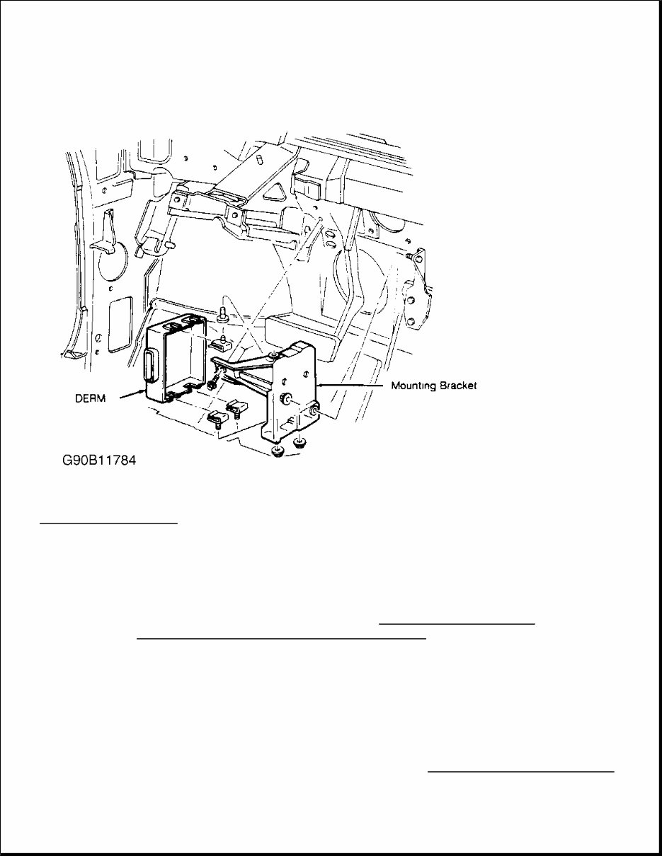
When a vehicle has been involved in a collision, certain components of the passive restraint system must be inspected or replaced. See PASSIVE RESTRAINT SYSTEM INSPECTION article in the GENERAL INFORMATION section for post-collision inspection information. REMOVAL & INSTALLATION DIAGNOSTIC ENERGY RESERVE MODULE (DERM) Removal & Installation 1. Before proceeding, follow air bag service precautions. See SERVICE PRECAUTIONS . Disable air bag system. See DISABLING & ACTIVATING AIR BAG SYSTEM . 2. Disconnect electrical connector from DERM, located under left side of instrument panel, right of steering column. Loosen 3 nuts, and remove DERM from vehicle. See Fig. 3 . To install, reverse removal procedure. Check INFLATABLE RESTRAINT indicator light to ensure system is functioning properly. See SYSTEM OPERATION CHECK under DIAGNOSIS & TESTING. WARNING: Before any repairs are performed, disconnect and shield battery ground. Because system has ability to retain voltage, remove SIR fuse and disconnect Yellow SIR connector at base of steering column. Wait 10 minutes before beginning service. All SIR system connectors use Connector Position Assurance (CPA) clips to ensure connector retention. Even if system is disconnected, use caution when working near steering column.
Fig. 3: Removing DERM Courtesy of GENERAL MOTORS CORP. PASSENGER COMPARTMENT DISCRIMINATING SENSOR Removal 1. Before proceeding, follow air bag service precautions. See SERVICE PRECAUTIONS . Disable air bag system. See DISABLING & ACTIVATING AIR BAG SYSTEM . 2. Passenger compartment discriminating sensor is located under right side of instrument panel. Remove 4 screws and glove box unit. Remove 2 nuts retaining Body Computer Module (BCM). Remove BCM electrical connectors and BCM from mounting bracket. Remove Connector Position Assurance (CPA) and disconnect electrical connector from sensor. Remove 2 sensor retaining bolts and sensor. Installation To install, reverse removal procedure. Tighten retaining bolts to 98 INCH lbs. (11 N.m). Check INFLATABLE RESTRAINT indicator light to ensure system is functioning properly. See SYSTEM OPERATION CHECK
The 1986-1993 Cadillac Allante Service & Repair Manual is an essential tool for resolving issues specific to the Cadillac Allante range. Whether you are a professional mechanic or a DIY enthusiast, this manual provides comprehensive, model-specific instructions and procedures designed to help you repair and maintain your vehicle with confidence.
This service manual offers:
Detailed technical data, wiring schematics, and electrical diagrams specific to the Cadillac Allante.
Step-by-step repair procedures with clear illustrations and drawings to simplify even complex repairs.
A complete list of car parts and accessory recommendations to enhance your vehicle’s performance.
Extensive maintenance, engine, control system, mechanical, and emission control guidelines tailored to the 1986-1993 models.
Engineered with the same precision as the information used by Cadillac engineers, this manual covers every repair from A to Z, backed by hundreds of photos, diagrams, and detailed specifications.
Compatible with both Windows and Mac systems, the manual is conveniently printable, allowing you to easily access and use the necessary repair data from your PC anytime.
Overall, the 1986-1993 Cadillac Allante Service & Repair Manual is an indispensable resource, providing reliable guidance and support for maintaining and repairing your Cadillac Allante effectively.
Recently Viewed
5,521,897Happy Clients
2,594,462eManuals
1,120,453Trusted Sellers
15Years in Business
Price:
Actual Price:
1986-1993 Cadillac Allante Service & Repair Manual