


GENERAL INFORMATION
Air Bag Deactivation Procedures - BMW
SPECIAL CARE DURING MECHANICAL REPAIRS
In some instances, it may be necessary to remove steering column or instrument panel to gain access to blower
motor housing, heater assembly, evaporator assembly, or other A/C-heater system related components. Observe
manufacturer service precautions when working on a vehicle equipped with an air bag system. See SERVICE
PRECAUTIONS .
Electrical sources should never be allowed near inflator on back of air bag module. Never probe air bag system
electrical wires with analog volt-ohmmeter or test light. Always disable air bag system before servicing vehicle.
See DISABLING & ACTIVATING AIR BAG SYSTEM procedure. Failure to do so could result in
accidental air bag deployment and possible personal injury.
If air bag system is not fully functional for any reason, DO NOT drive vehicle until system is repaired and is
again operational. DO NOT remove bulbs, modules, sensors or other components, or in any way disable system
from operating normally. If air bag system is not functional, park vehicle until system is repaired and functions
properly.
SYSTEM OPERATION CHECK
1. Turn ignition switch to ON position, with engine off. SRS is operational if AIR BAG warning light
comes on and then goes out after about 6 seconds with engine off.
2. If AIR BAG warning light remains on, this indicates a fault in the SRS. If AIR BAG warning light fails to
illuminate when ignition is first turned on, this indicates bulb is faulty or there is a fault in the wiring
circuit to the bulb.
WARNING: To avoid injury from accidental air bag deployment, read and carefully
follow all SERVICE PRECAUTIONS and DISABLING & ACTIVATING AIR
BAG SYSTEM procedures.
WARNING: Some vehicles are equipped with a passenger's side air bag ON/OFF
switch. This switch should NOT be used in place of specified vehicle air
bag system disabling and activating procedures.
WARNING: DO NOT use any type of back-up power supply (memory saver) from
outside vehicle to avoid memory loss in memory systems, if equipped.
Back-up power supplies can provide enough voltage to deploy air bags.
NOTE: When the battery is disconnected, vehicle computer and memory system may
lose data. Driveability problems may exist until computer systems have
completed a relearn cycle.

SERVICE PRECAUTIONS
Observe these precautions when working on SRS:
When working around steering column and before any repairs are performed, disable SRS. See
DISABLING & ACTIVATING AIR BAG SYSTEM .
Before straightening damaged metal or arc-welding, disable SRS and disconnect front sensors, front air
bag modules, seat belt tensioners (if equipped) and side air bag modules connectors. See DISABLING &
ACTIVATING AIR BAG SYSTEM .
After disabling SRS, wait at least 5 minutes before servicing vehicle. SRS control unit maintains SRS
voltage for about 5 minutes after system is disabled. Servicing SRS before 5 minutes may cause
accidental air bag deployment and possible personal injury.
Always wear safety glasses and gloves when handling a deployed air bag module. Air bag module may
contain sodium hydroxide deposits, which irritates skin.
Handle sensors carefully. Never strike or jar sensors. All sensors and mounting bracket bolts must be
tightened to specification to ensure proper sensor operation.
Never use any SRS component that has been dropped from a height of 2 feet or higher.
DO NOT repair any SRS component or wiring harness; replace only. Wiring harnesses and connectors
are Orange for immediate identification.
To avoid air bag deployment, DO NOT use self-powered electrical test equipment on driver's or
passenger's air bag modules. This equipment includes battery powered circuit testers, voltmeters and
ohmmeters.
Always handle air bag module with trim cover away from body. Always place air bag module on
workbench with trim cover up, away from loose objects. DO NOT leave air bag modules unattended.
Never expose SRS components to temperatures greater than 167°F (75°C).
Front air bag modules, belt tensioners and side air bag modules (if equipped) can only be checked while
installed in vehicle and using a BMW Service Tester/DIS. Only attempt SRS inspections using specified
procedures and checking devices.
Never expose any SRS system components to cleaning agents such as solvents, gasoline, lye, etc.
DISABLING & ACTIVATING AIR BAG SYSTEM
1. Before proceeding, see SERVICE PRECAUTIONS . Retrieve fault codes before disconnecting battery.
Ensure radio and ignition is off. Disconnect and shield negative battery cable. WAIT at least 5 minutes
(one minute on 7-series models) for energy capacitor in SRS control unit to discharge. System is now
disabled.
2. Ensure no one is inside vehicle and connect negative battery cable. System is now activated. Perform
system operation check to ensure system is functioning properly and no fault codes are set. See SYSTEM
CAUTION: Ensure radio is off before disconnecting battery. This will prevent damage
to radio microprocessor. On cars with radio codes, ask customer for radio
code card before disconnecting battery. Make a note of stored
transmitters, restore these transmitters after reconnecting the battery.

OPERATION CHECK .
ACCESSORIES AND EQUIPMENT
Audio, Navigation and Anti-Theft - SI Techniques - X3
MULTIPLE RESTRAINT SYSTEM 4
E83
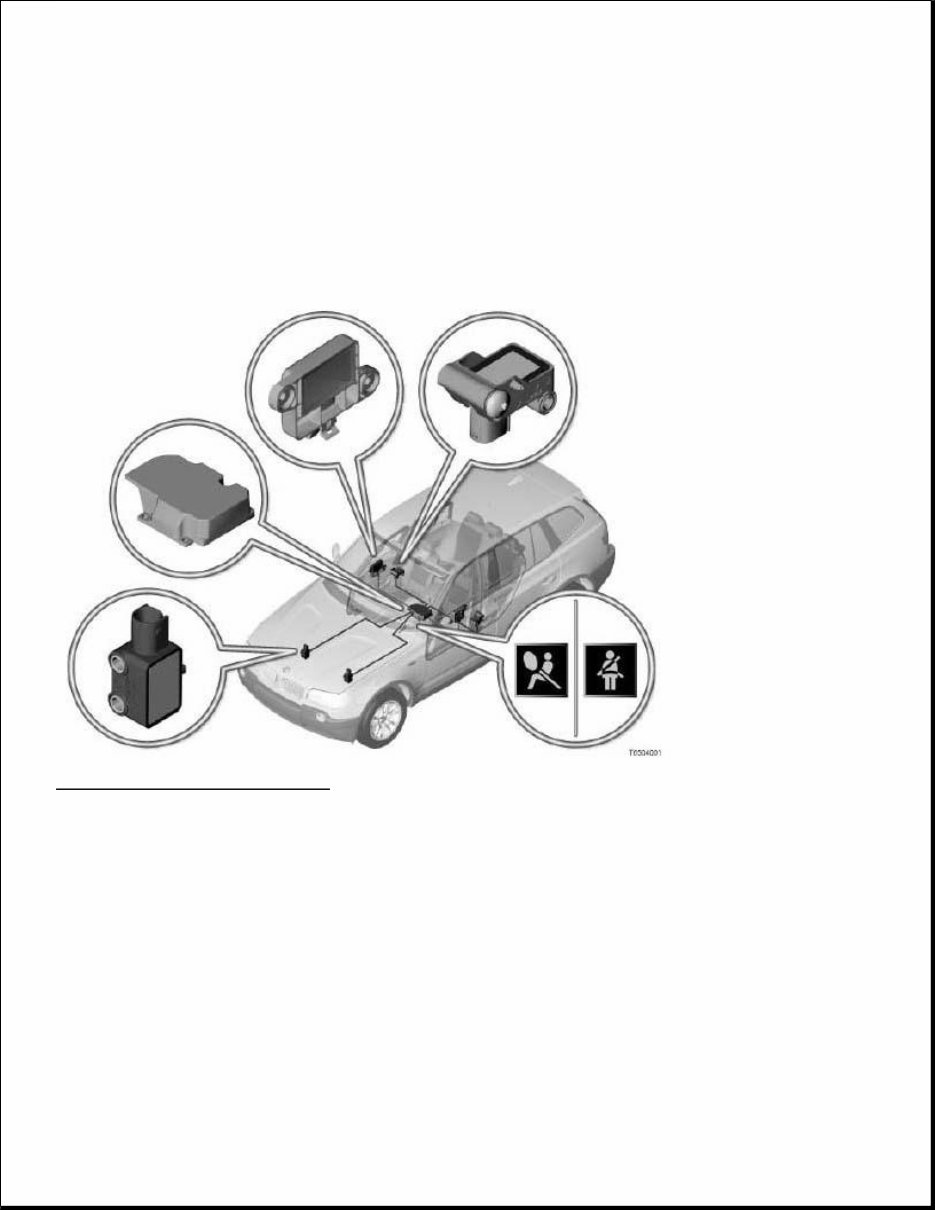
Fig. 1: Multiple Restraint System 4
Courtesy of BMW OF NORTH AMERICA, INC.
INTRODUCTION
Multiple restraint system 4 is a further development of the multiple restraint system (MRS) in the E46.
The MRS performs the following functions:
Detects an accident situation which could be critical for the occupants
Activates the necessary restraint systems (selectively, depending on the severity and type of accident)
New features, compared to the previous MRS (E46):
2 airbag front sensors

Front left door satellite and front right door satellite
Left-hand B-pillar satellite and right-hand B-pillar satellite with lateral and longitudinal acceleration
sensors
The MRS control unit interfaces have been expanded to 75 pins (50 pins in the E46).
Discontinuation of the MRS acceleration sensors under the front seats
The lateral acceleration sensors are now in the left and right-hand B-pillar satellites.
An advantage compared to the previous multiple restraint system is more precise airbag trigger control
BRIEF DESCRIPTION OF COMPONENTS
The following sensors detect the direction and severity of an impact:
Airbag front sensors
The airbag front sensors are longitudinal acceleration sensors. The front airbag sensors detect a head-on
collision.
Front left door satellite and front right door satellite
There is a pressure sensor in each satellite door. The pressure sensors detect a side impact.
Left-hand B-pillar satellite and right-hand B-pillar satellite
The B-pillar satellites each contain a lateral acceleration sensor and a longitudinal acceleration sensor.
The sensors are arranged at 90 degrees to each other.
Acceleration sensors in the MRS control unit
There is a lateral acceleration sensor and a longitudinal acceleration sensor in the MRS control unit. The
sensors are arranged at 90 degrees to each other.
The following components provide input signals for the multiple restraint system (MRS):
Seat-belt-lock switch (driver and passenger seat)
The seat-belt-lock switch indicates whether the seat belt is engaged or not.
The seat-belt-lock switch is powered by the MRS control unit. The power consumption of the switch
forms the signal for the switch position (seat belt engaged or not engaged).
The seat-belt-lock switches on the driver and passenger seats are permanently monitored when terminal R
is ON. For example, if a seat belt is released while the vehicle is in motion, there is a seat-belt warning.
A seat-belt warning is started when terminal 15 is ON.

The seat-belt warning indicates to the occupants that they should fasten their seat belts.
The seat-belt warning is an extension of the previous time-dependent display (seat-belt warning lamp in
the instrument cluster for approximately 6 seconds after terminal 15 is switched ON).
Seat-belt-lock switch (US version)
When terminal 15 is ON, a seat-belt warning lamp lights up and a warning sounds if the driver and
passenger seat belts are not engaged. Once the driver and passenger seat belts are engaged in the
corresponding buckles, the seat-belt warning lamp and the audible warning are switched off.
If a seat belt is released while the vehicle is in motion, the seat-belt warning lamp lights up and a warning
signal sounds for approximately 90 seconds.
The MRS control unit uses the signal from the seat-belt-lock switch to determine whether an airbag
should be triggered at stage 1 (seat belt not engaged) or at stage 2 (seat belt engaged).
Passenger seat occupancy detector
The passenger seat-occupancy detector recognizes whether the seat is occupied or not. When a weight is
placed on the seat, resistance in the seat-occupancy mat changes.
If the multiple restraint system (MRS) triggers the driver's airbag, the passenger airbag and belt tensioner
will not be triggered if the passenger seat is unoccupied.
Passenger seat-occupancy detector (US version)
Due to legal requirements in the USA, a child seat securing a one-year-old child which is placed on the
passenger seat must be automatically detected. Upon detection, the airbags on the passenger side are
automatically deactivated (passenger airbag and front right-hand side airbag).
The passenger seat-occupancy detector is based on an evaluation of the surface pressure generated by the
person sitting down. The electronic evaluation decides whether a person or a child seat is occupying the
seat. If a one-year-old child in a child seat is detected, the airbags on the passenger side are deactivated
(warning lamp for passenger-airbag deactivation lights up).
Several control units make up the multiple restraint system (MRS):
Multiple restraint system control unit
All gas generators and sensors in the multiple restraint system (MRS) are connected to the MRS control
unit.
The MRS control unit evaluates the data it receives from the sensors. In the event of a head-on or side
impact, the control unit determines whether it is necessary to deploy any airbags and which airbags
should be deployed.

Digital motor electronics or digital diesel electronics
When an airbag is triggered, the electric fuel pump is switched off by the DME or DDE (DME = Digital
Motor Electronics, DDE = Digital Diesel Electronics).
Signal path: MRS control unit -> K bus -> instrument cluster -> PT-CAN -> DME or DDE -> direct line -
> fuel-pump relay> electric fuel pump
Instrument cluster
The instrument cluster triggers the optical and audible seat-belt warning.
The MRS control unit only sends a message on the status of the seat belts and the seat-occupancy
detector.
The instrument cluster receives the status message from the MRS control unit via the body bus when
terminal R is ON. Depending on the status, the optical and audible warning is triggered when terminal 15
is ON.
The following components are controlled:
Ignition circuit for the airbags
With the maximum amount of equipment, the multiple restraint system consists of the following ignition
circuits:
Driver's airbag (stage 1)
Passenger airbag (stage 1)
Driver's airbag (stage 2)
Passenger airbag (stage 2)
Side airbag in the front left door
Side airbag in the front right door
Side airbag in the left rear door (option 261)
Side airbag in the right rear door (option 261)
Left-hand head airbag
Right-hand head airbag
Belt tensioner, front left
Belt tensioner, front right
Safety battery terminal
Driver and passenger airbag
The driver and passenger airbag reduce the risk of injury to the occupants in the event of a head-on collision.

The driver airbag is located in the center pad on the steering wheel. The passenger airbag is integrated into the
instrument panel above the glove compartment. The driver and passenger airbags each have a dual-stage gas
generator. The airbags are triggered at different levels depending on the severity of the accident.
Side airbags
The side airbags reduce the risk of injury to the occupants in the event of a side collision. The side airbags are
located behind the door trim panel. The side airbags are always triggered at stage 1.
Head airbags
The head airbags protect the occupants' head in the event of an impact to the side body panels. They also protect
the head from objects that may enter the vehicle.
Belt tensioners
The pyrotechnic belt tensioners pull the front seat belts tight against the occupants' body in the event of a head-
on or rear-end collision.
In a normal situation, the seat belt does not sit completely tight against the body. The seat belt always has a
small degree of play to guarantee the occupants an adequate degree of comfort. The play of a fastened seat belt
is know as slack. The prevent the negative effects of this slack, the seat belt buckle is pulled down several
centimeters by gas generators in the event of an accident. This pulls the seat belt tight.
Safety battery terminal
Depending on the severity of the accident, the safety battery terminal disconnects the starter motor and the
alternator from the power circuit. This minimizes the risk of short circuits in a serious accident. The trigger
signal comes from the MRS control unit.
Airbag warning lamp
The airbag warning lamp shows the operational capability of the multiple restraint system (MRS). The
airbag warning lamp is located in the instrument cluster and is controlled by the MRS control unit (via the
K bus).
After the ignition is switched on, the MRS performs a self test. While this is being run, the airbag warning
lamp lights up (approximately 3 to 5 seconds). When the system is ready, the airbag warning lamp goes
out.
If, during the self test or while the vehicle is in motion, the MRS control unit detects an existing fault or
one that has been stored, the airbag warning lamp remains on.
If the MRS detects a fault, the operational capability is partially maintained, if possible, subject to the
following:
If a fault is detected in an MRS circuit, only the affected circuit is deactivated. The other airbags

and belt tensioners remain operational.
If there is a fault in the airbag warning lamp circuit, the lamp does not light up. If there is no other
fault, the MRS remains fully operational.
If there is an internal fault in the MRS control unit or in the power supply, the entire system is deactivated.
Deactivation of the passenger airbag and the front right-hand side airbag
The passenger airbag and the front right-hand side airbag are deactivated by a coding procedure.
Warning lamp for passenger-airbag deactivation (US version)
If the warning lamp for passenger-airbag deactivation (passenger airbag off lamp) is lit, both airbags on
the passenger side have been deactivated: the passenger airbag and the front right-hand side airbag The
passenger airbag off lamp is constantly monitored by the MRS control unit. A fault in the power supply
or a defective lamp is stored in the MRS control unit's fault memory. If this occurs, the airbag warning
lamp is switched on.
The passenger airbag OFF lamp is located in the control panel in the overhead console.
Shutting off the fuel pump
When an airbag is triggered, the fuel feed is also shut off.
Mechanical components in the multiple restraint system (MRS):
Seat belts
The seat belts are the primary restraint system for all occupants. A lap and diagonal automatic belt is
fitted on each seat.
If there is a very severe impact, the seat belt strap may cause injuries to the chest of the person it is
securing. To minimize this risk, the front seat belts are fitted with belt force limiters as standard. The belt
force limiters allow the seat belt to be unrolled in a controlled fashion if the belt force exceeds a critical
value. The risk of injury due to the belt force acting on the body is therefore reduced.
Passive knee protection (US version)
Not every state in the USA has a requirement for seat belts to be worn. Therefore, the E83 also has
additional plastic impact protection on the driver and passenger sides. In the event of an impact, the
passive knee protection provides a flat support for the lower leg, especially if the front passengers are not
wearing their seat belts. This causes the forwards movement of the upper body to be controlled towards
the relevant airbag (driver or passenger airbag).
SYSTEM FUNCTIONS

Triggering the multiple restraint system
Emergency call (EURO version)
Emergency call (US version)
Triggering the multiple restraint system
Extensive testing has allowed the triggering thresholds to be determined for all possible types of accidents.
Various triggering thresholds were set for activating the different restraint systems:
The multiple restraint system comprises:
Belt tensioners
Front airbags
Side airbags
Head airbags
Safety battery terminal
Electric fuel pump
The following examples illustrate how the various restraint systems are triggered:
Head-on collision
The belt tensioners, the front airbags and the safety battery terminal are triggered if the head-on collision
is so severe that the triggering threshold of the MRS control unit is exceeded.
The belt tensioners have a lower triggering threshold than the front airbags. The belt tensioners are
therefore triggered earlier.
If the seat-belt-lock switch is faulty, the triggering threshold for the front airbag on this side is lowered.
Even though there is a fault message, the MRS control unit will try to trigger the belt tensioners.
If the seat-occupancy detector is faulty, the control unit assumes that the passenger seat is occupied. The
restraint systems are activated.
The electric fuel pump is switched off. An automatic emergency call is initiated (only in vehicles with the
relevant equipment fitted).
Side impact
The side impact must be severe enough for the triggering threshold in the MRS control unit to be
exceeded.
The side airbag and the head airbag are deployed on the side affected. The safety battery terminal is also
triggered.
You're Reading a Preview
What's Included?
 Lifetime Access
Fast Download Speeds
Online & Offline Access
Access PDF Contents & Bookmarks
Full Search Facility
Print one or all pages of your manual
$37.99
2009 BMW X3-Series E83 Service and Repair Manual
Viewed 24 Times Today

What's Included?
Lifetime Access
Fast Download Speeds
Online & Offline Access
Access PDF Contents & Bookmarks
Full Search Facility
Print one or all pages of your manual
$37.99

Secure transaction
What's Included?
Lifetime Access
Fast Download Speeds
Online & Offline Access
Access PDF Contents & Bookmarks
Full Search Facility
Print one or all pages of your manual
Description
This 2009 BMW X3-Series E83 Service and Repair Manual is an essential resource for any BMW X3 owner. It provides detailed instructions and diagrams to help you maintain, service, and repair your vehicle. Whether you are a DIY enthusiast or a professional mechanic, this manual will assist you in keeping your BMW X3 in top condition.
Key features of this manual include:
- Comprehensive step-by-step instructions for all maintenance and repair tasks
- Clear and easy-to-follow diagrams and illustrations
- Covers all aspects of the 2009 BMW X3-Series E83, including engine, transmission, suspension, electrical system, and more
- Troubleshooting guides to help diagnose and fix common problems
Models covered in this manual:
- 2009 BMW X3-Series E83 2.0i
- 2009 BMW X3-Series E83 2.5i
- 2009 BMW X3-Series E83 3.0i
Whether you need to perform routine maintenance, diagnose a problem, or tackle a major repair, this Service and Repair Manual is an invaluable resource for BMW X3 owners. Get your copy today and keep your BMW running smoothly.


