61 00 ... Notes on handling wiring harnesses and cables The following applies in general: To avoid damage, observe the following instructions: Avoid compressive and tensile loads To ensure professional repairs, perform repair work only with BMW-approved or recommended special tools and spare parts Make sure cables are laid without kinks or abrasions Ensure non-contacting routing at sharp-edged body parts; use edge protection if necessary Secure additionally laid cables/leads with cable ties The following additionally applies Shielded cables Joins in the shield can cause problems with regard to noise radiation and interference immunity. Consequently, distinctions have to be drawn between the following types: Coaxial cable Shielded RTK031 coaxial lines may only be repaired using special crimping tools . CVBS cables CVBS cables may not be repaired. CVBS cables must be replaced in their entirety. HSD cables HSD cables may not be repaired. HSD cables must be replaced in their entirety. Fibre - optic cables: Note: Fibre-optic cables are coloured differently as follows: Green = MOST (Media OrientedSystems Transport) optical fibre Yellow = ISIS (Intelligent Safety Integration System) optical fibres Orange=repair fibre-optic cables 1/2
Important! Optical fibres are permitted to show only one junction point (bridge). Replace optical fibres if necessary Smallest permissible bending radius is 25 mm Avoid effects of heat ≥ 85 ° Treating cables and fibre - optic cables FlexRay: It is possible to repair the FlexRay. In the event of damage, the cables can be joined with conventional butt connectors and heat - shrink tubing . Note: FlexRay lines may only reveal one separation point (bride); renew complete line if necessary. The cable is a twisted cable. If possible, maintain twisted cable after repair. Airbag lines: Repairing airbag cables 2/2
1. Aerial amplifier 2. Blocking circuit 3. AM choke (US vehicles only) 4. Back ‐ up aerial 5. Interference suppression filter 65 20 ... Overview of aerial diversity 1/1
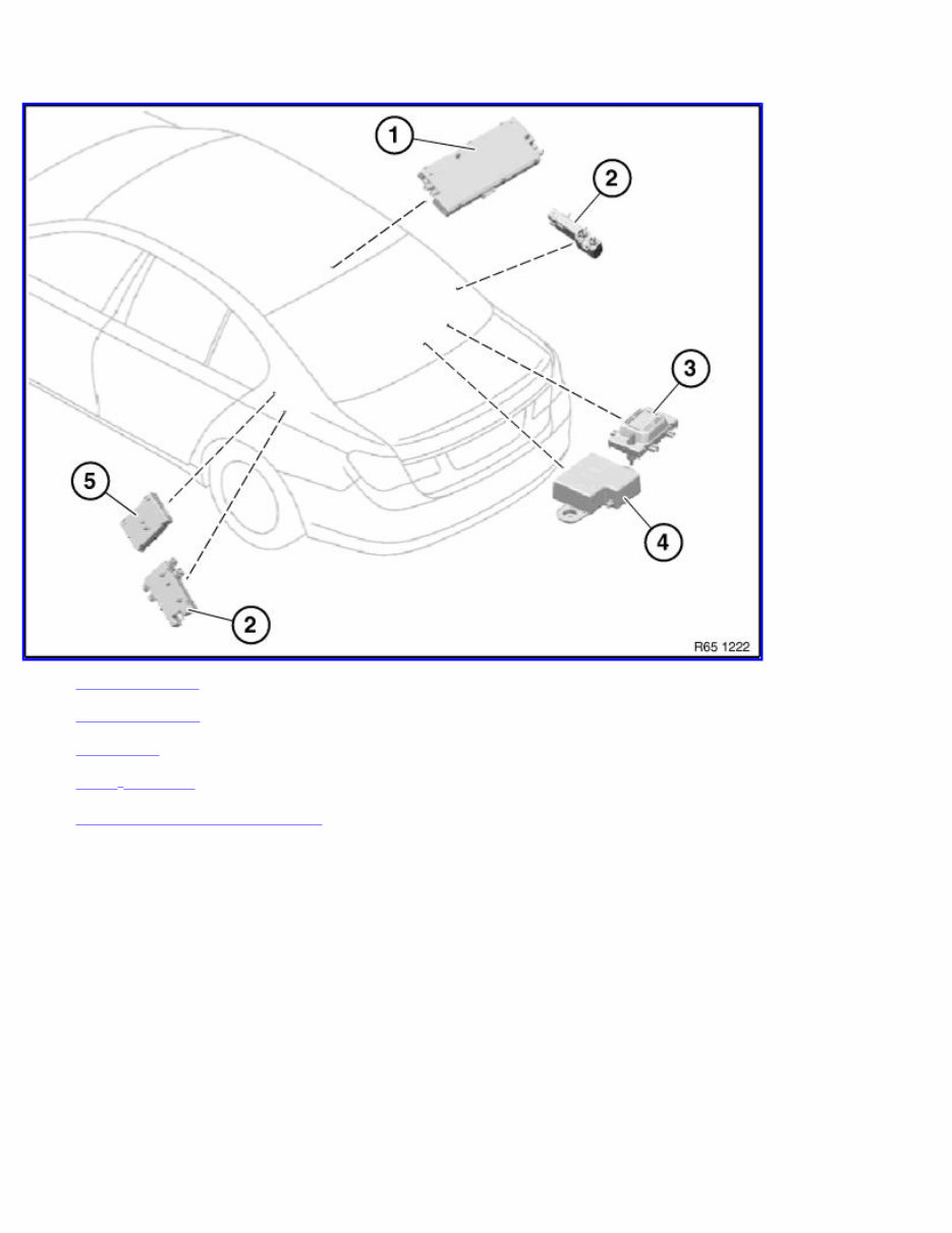
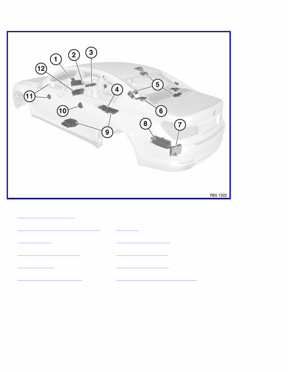
65 00 .. Overview of audio components 1 Speaker (in dashboard ) 7 Satellite tuner 2 Central Information Display (CID) 8 Amplifier 3 DVD changer 9 Central bass speaker 4 DVD player, rear console 10 Speaker (door, rear) 5 Aerial diversity 11 Speaker (door, front) 6 Speaker (in storage shelf) 12 Car Information Computer (CIC) 1/1
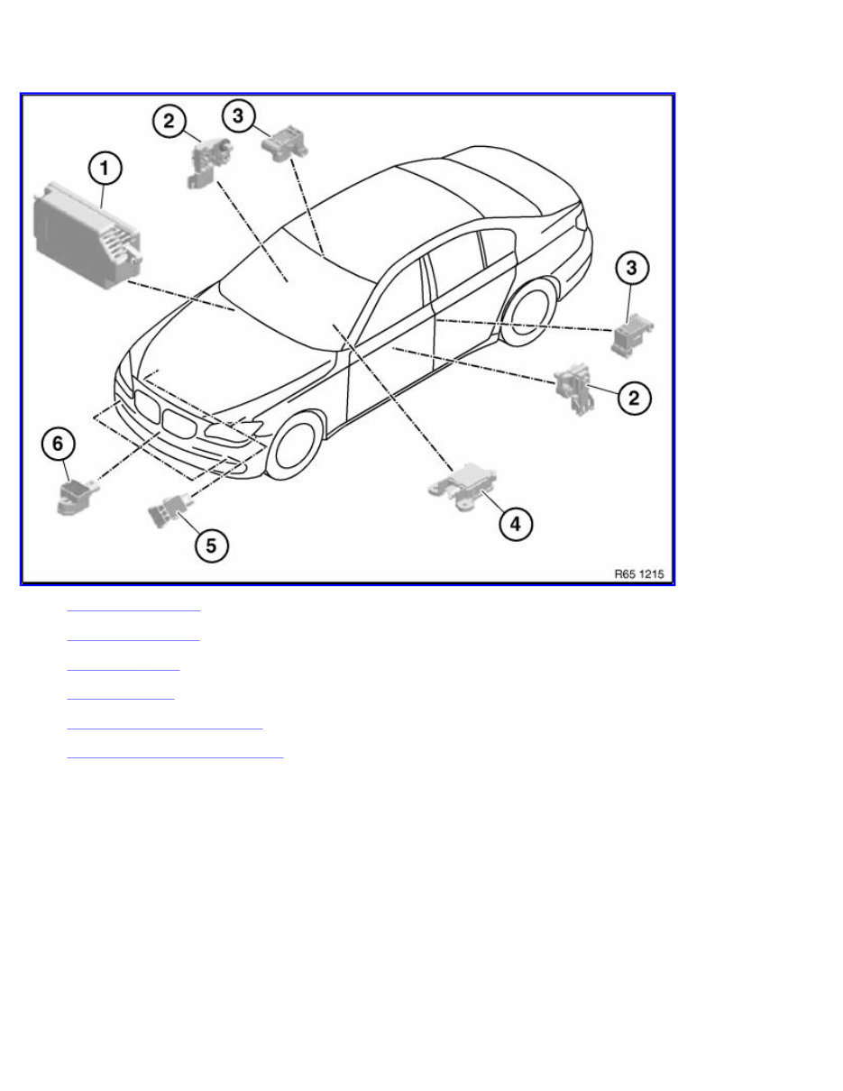
1. Airbag control unit (storage tray, passenger side) 2. Sensor, front door (left/right) 3. Sensor, B - pillar (left/right) 4. Central sensor (under centre console) 5. Acceleration sensors, front (left/right) 6. Sensor, pedestrian protection (middle/left/right) 65 77 ... Overview of sensors for airbag system and pedestrian protection 1/1
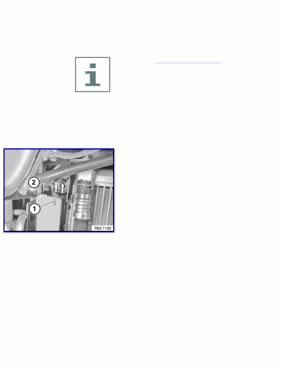
65 81 060 Remove and installing/replacing outside temperature sensor (N52T,N53,N57) Remove ornamental grille for bumper trim (side right) Unclip outside temperature sensor (1) in direction of arrow from mounting and feed out into empty space (2). Disconnect plug connection (1) and remove outside temperature sensor (2). Installation: Make sure outside temperature sensor (1) is correctly engaged in mounting. 1/1
65 81 060 Remove and installing/replacing outside temperature sensor (N54, N55, N63, N74, N57S) Remove front right wheel arch cover (front section) Unclip outside temperature sensor (1) in direction of arrow from mounting and pull out. Disconnect plug connection (2) and remove outside temperature sensor (1). Installation: Clip temperature sensor (1) into place. Close plug connection (2). Make sure outside temperature sensor (1) is correctly engaged in mounting. 1/1
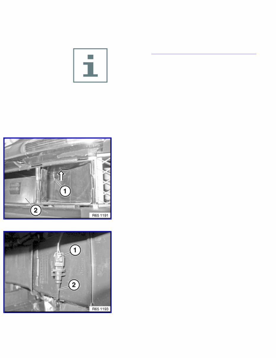
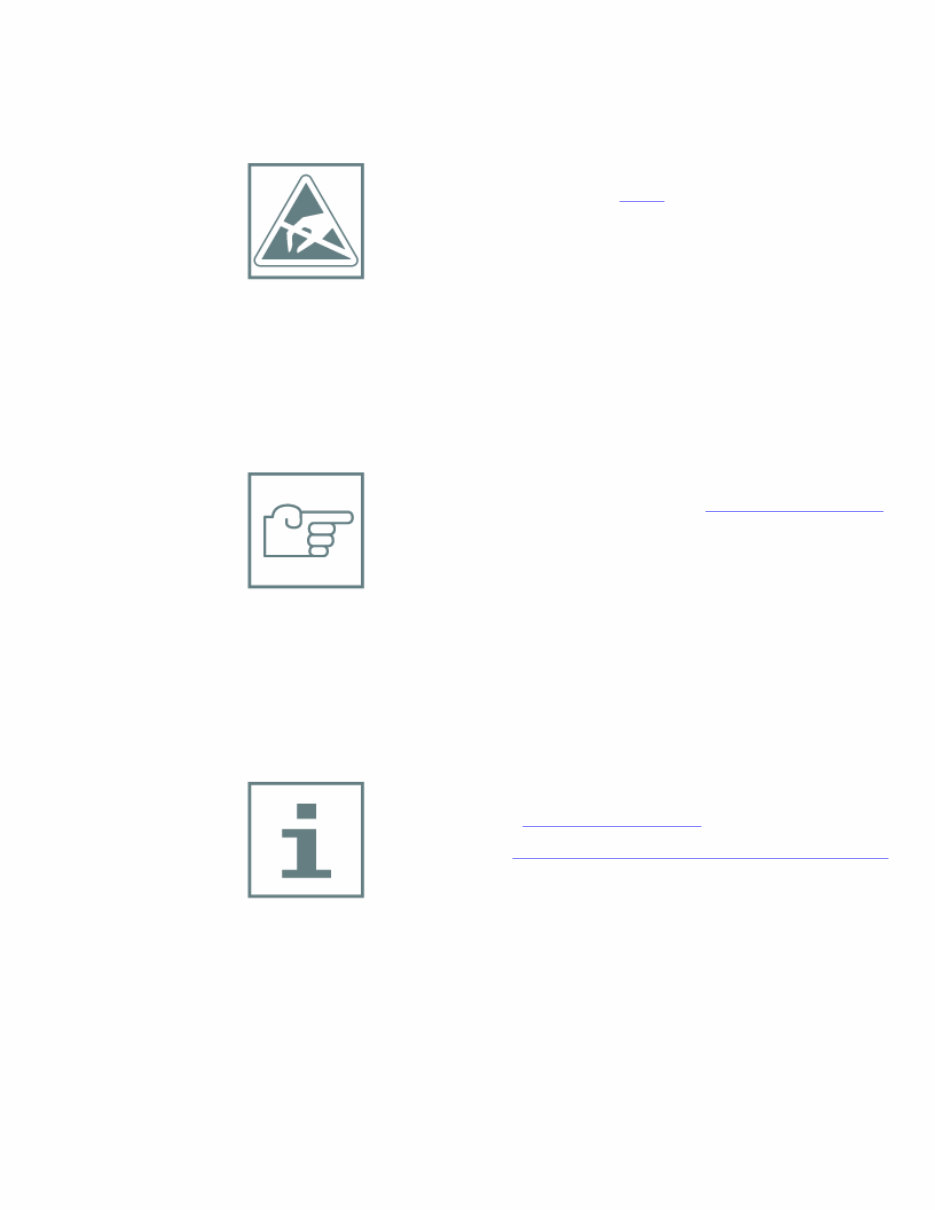
65 12 072 Removing and installing (replacing) amplifier (Top HiFi system) Important! Read and comply with notes on protection against electrostatic discharge (ESD protection). Note: Comply with notes and instructions on handling optical fibres . Necessary preliminary work: Clamp off negative battery cable . Remove luggage compartment wheel arch panel on left . Release screw (1). Remove amplifier (2) in direction of arrow from holder (3). Unlock plug connections and disconnect. 1/3
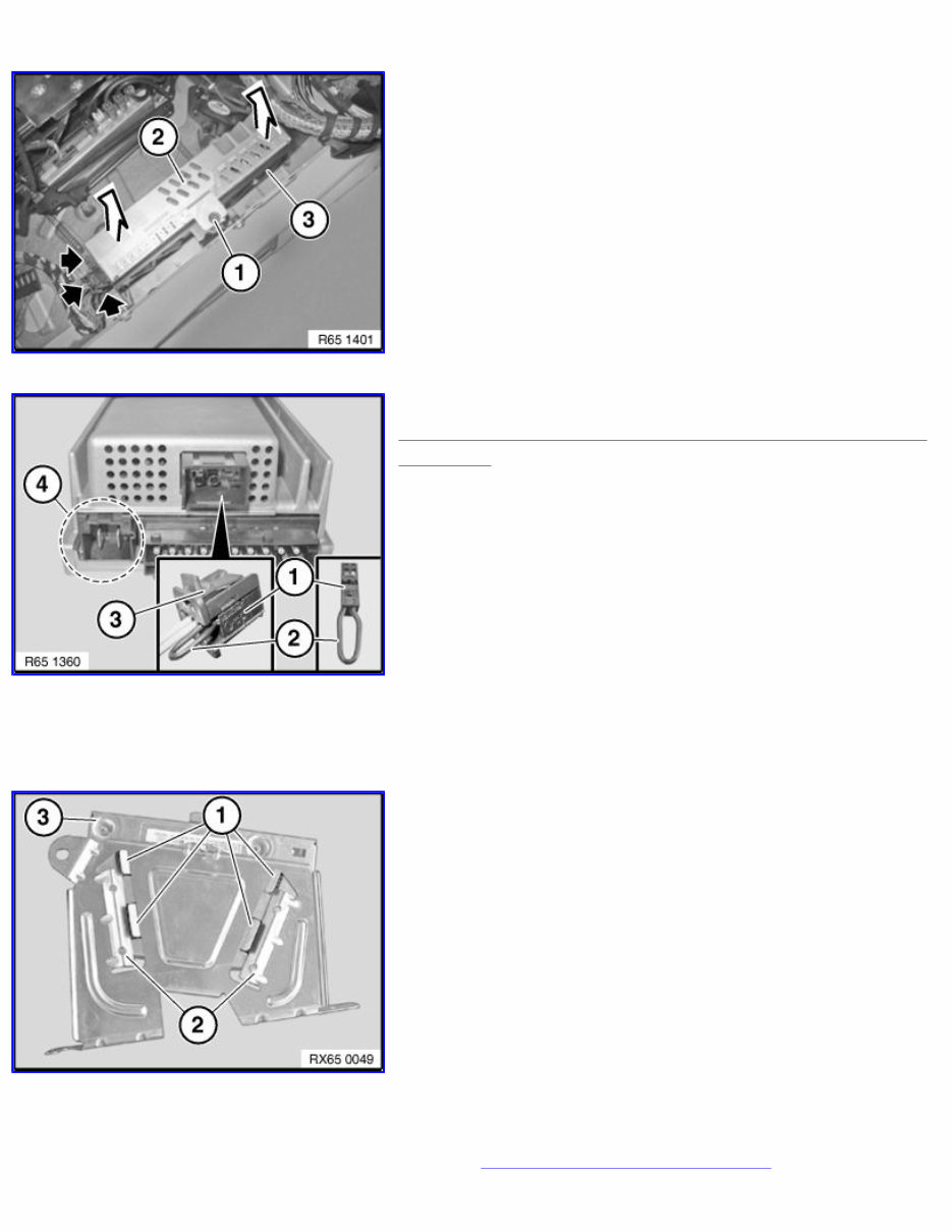
Note: Until 09/2009 a Top Hifi amplifier with a different pin assignment is installed! Install cable jumper consisting of socket (1) (BMW Parts Service 6901844) and wire jumper (2) in connector (3). Create wire jumper (2) from wire (cross-section 0.75 mm²) and two stops (BMW Parts Service 1393724). Then connect pins 1 and 2 in socket (1) with wire jumper (2). Note Connector chamber (4) is not included in current version and remains unused in new replacement Top HiFi amplifier! Note: Picture for example purposes. Installation note: Tabs (1) must be correctly slid into guide (2). Check that amplifier (3) is securely seated. Replacement: Carry out vehicle programming and encoding . 2/3
If you are in need of a repair manual for your 2011 BMW 750I, look no further. Our accessible repair manual software is perfect for both professional mechanics and DIY enthusiasts. In the past, traditional service manuals in book format were costly and inconvenient. Our repair manual software provides the same information at a much lower cost and in a more convenient format.
Whether you need to fix the brakes, replace suspension components, get the engine running, or perform standard maintenance, this repair manual software for the BMW 750I has got you covered. It includes comprehensive service information for the brakes, engine, suspension, steering, drivetrain, electrical systems, heating, air conditioning, and more.
By using this 2011 BMW 750I repair manual software, you can save a significant amount of money on vehicle repairs. Mechanics often charge high fees, but with this manual, you can work on your vehicle yourself. The software is compatible with Windows, Mac computers, smartphones, and tablets, making it easy to access and use.