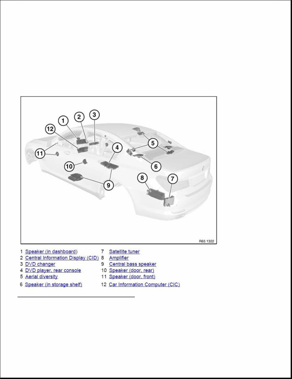
ACCESSORIES AND BODY, CAB Audio, Navigation and Anti-Theft - Repair 6510 RADIO 65 00.. OVERVIEW OF AUDIO COMPONENTS Fig. 1: Overview Of Audio Components (1 Of 2) Courtesy of BMW OF NORTH AMERICA, INC. 6511 MONO RADIO 65 00.. OVERVIEW OF AUDIO COMPONENTS
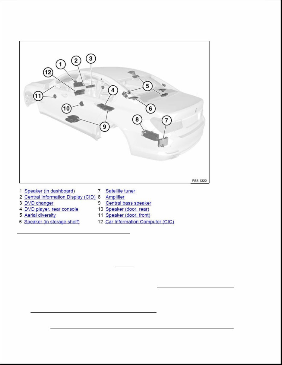
Fig. 2: Overview Of Audio Components (2 Of 2) Courtesy of BMW OF NORTH AMERICA, INC. 65 11 075 REMOVING AND INSTALLING/REPLACING DVD CHANGER Necessary preliminary tasks F01/02: DISCONNECT BATTERY EARTH CABLE . F03: Disconnect both battery earth cables Remove DECORATIVE STRIP ON STORAGE COMPARTMENT/DVD CHANGER IMPORTANT: Read and comply with NOTES on protection against electrostatic damage (ESD protection). NOTE: Comply with notes and instructions on HANDLING OPTICAL FIBRES .
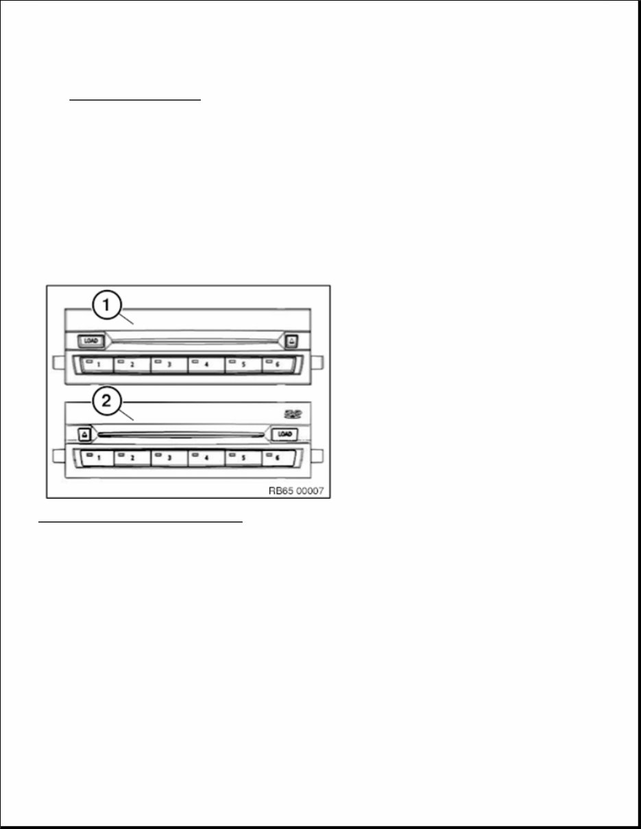
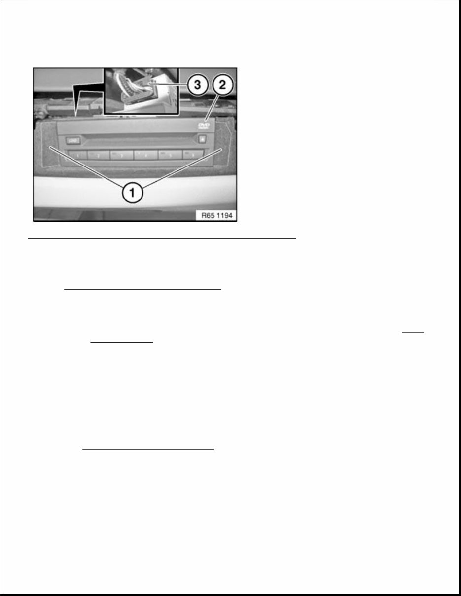
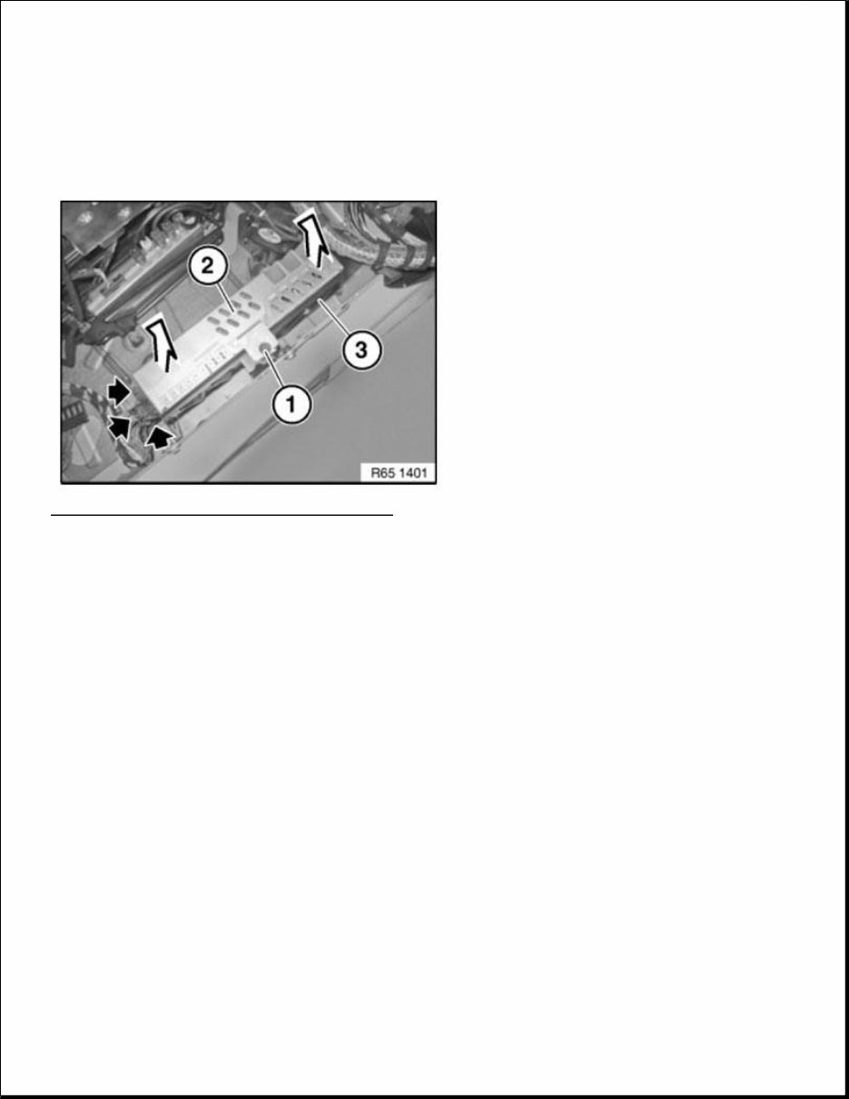
INSTRUMENT PANEL When a new DVD changer (2) is being replaced (as of 09/09) , conversion to ISTA/P must be carried out. ("Converting replacement DVD changer ") If the old DVD changer (1) is installed (up to 09/09 ), this conversion to ISTA/P must not be carried out. The old DVD changer (1) and the DVD changer (2) have an external difference in that the Load and Eject buttons are swapped round. Fig. 3: Identifying New DVD Changer Courtesy of BMW OF NORTH AMERICA, INC. Unclip trims (1) with a suitable tool and release screws behind. Pull DVD changer (2) out of guide. Unlock associated plug connection (3) and disconnect. Remove DVD changer (2). NOTE: Affects all vehicles from series introduction to 09/2009 with DVD changer (SA696)!
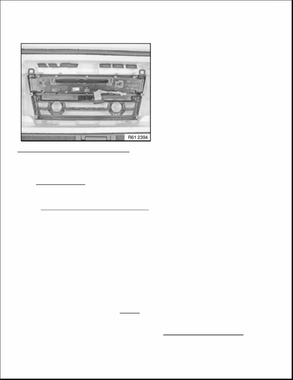
Fig. 4: Identifying Unclip Trims, DVD Changer And Plug Connection Courtesy of BMW OF NORTH AMERICA, INC. Replacement: Carry out VEHICLE PROGRAMMING/CODING . 61 31 823 REPLACING AUDIO UNIT Necessary preliminary work Remove RADIO AND IHKA CONTROLS IMPORTANT: Read and comply with notes on protection against electrostatic damage (ESD PROTECTION) . IMPORTANT: Use of supplied gloves is mandatory Carry out installation in a dust-free workshop area only. To avoid damage, do not touch or dirty the display field. IMPORTANT: Retrofitting must only be done in the supplied installation cassettes. Use of supplied gloves is mandatory, so that there is no damage to the display.
Fig. 5: Identifying Radio And IHKA Controls Courtesy of BMW OF NORTH AMERICA, INC. Installation note: Modify IHKA CONTROLS on new audio unit. Replacement Carry out VEHICLE PROGRAMMING/ENCODING . 6512 STEREO RADIO, AMPLIFIER 65 12 315 REMOVING AND INSTALLING (REPLACING) HEAD UNIT IMPORTANT: Risk of damage! There is a hard disk installed in the head unit. Carry out mechanical work on the head unit and adjacent components with care. Avoid subjecting the head unit to vibration/shocks. IMPORTANT: Read and comply with NOTES on protection against electrostatic damage (ESD protection). NOTE: Comply with notes and instructions on HANDLING OPTICAL FIBRES .
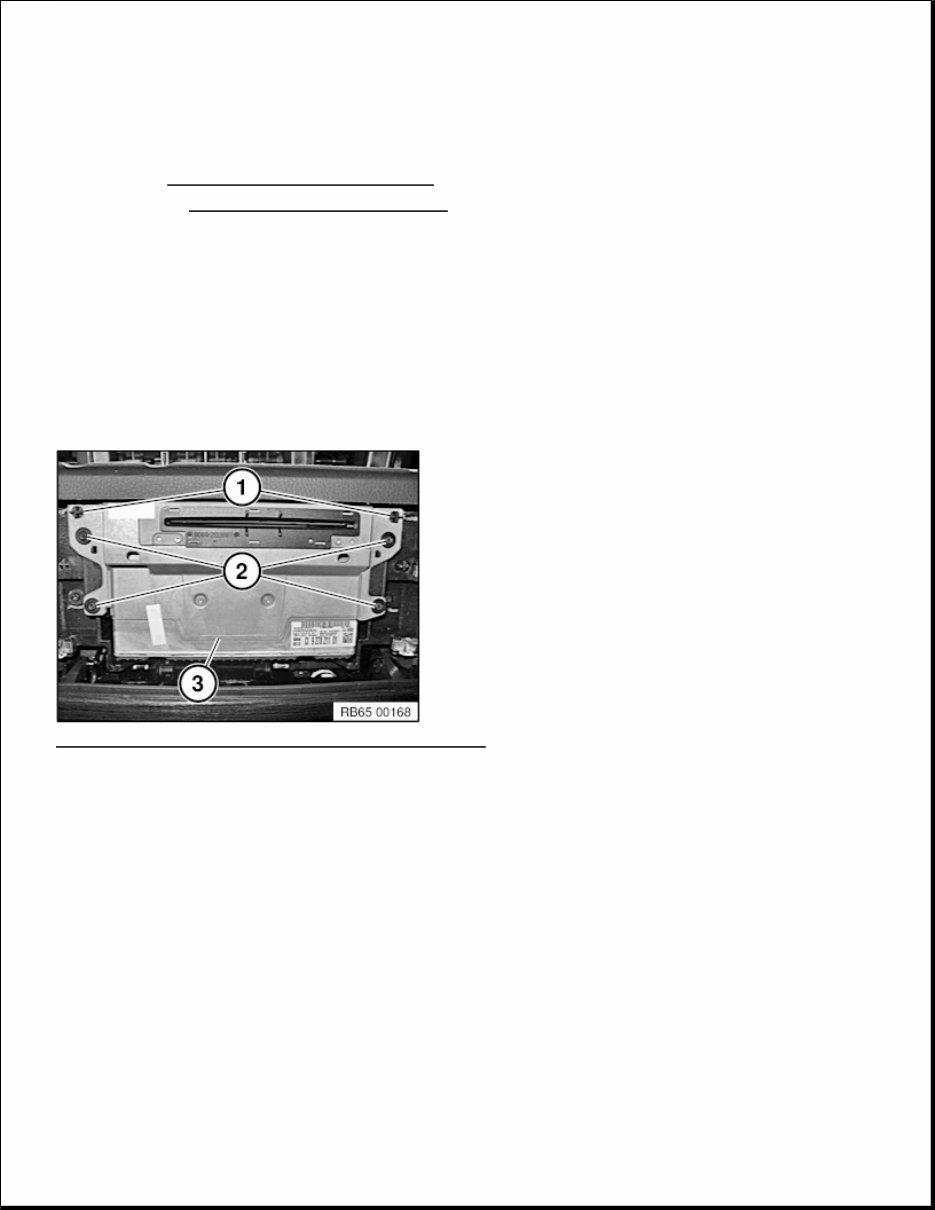
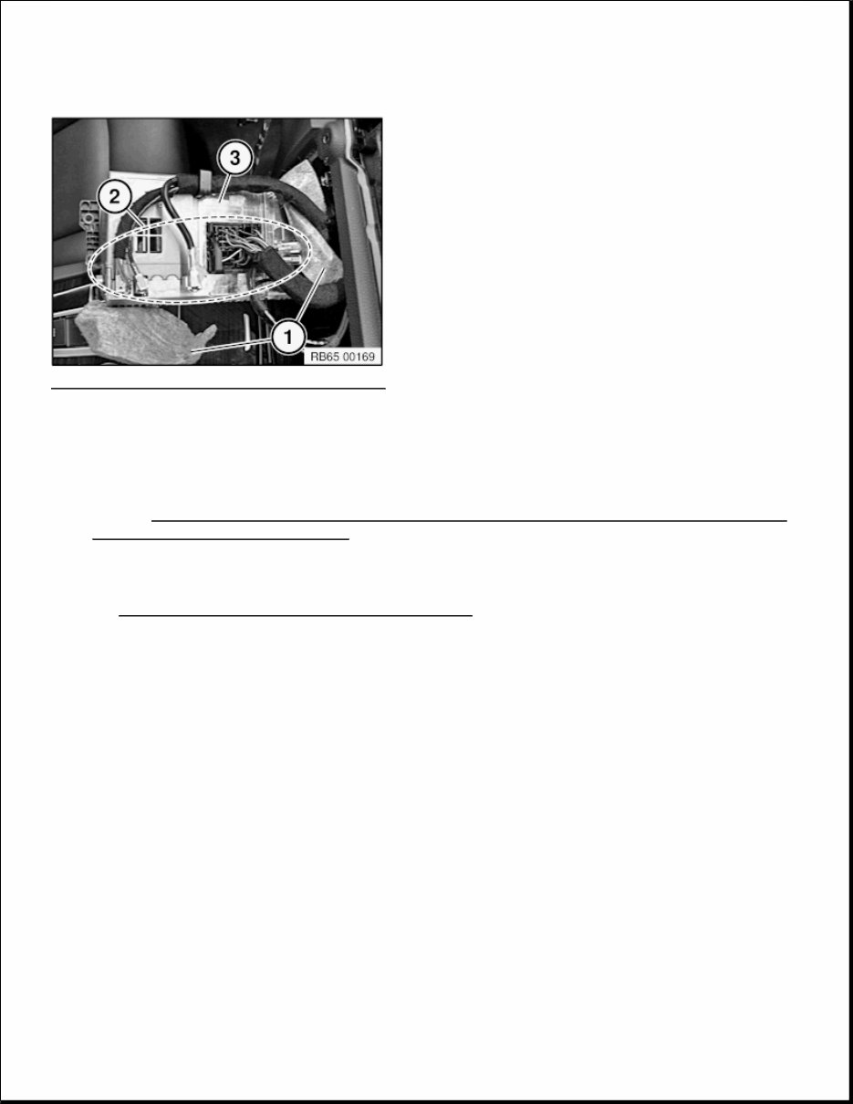
Necessary preliminary work: Remove RADIO AND IHKA CONTROLS . Disconnect NEGATIVE BATTERY CABLE (F03: disconnect both negative battery cables). Unfasten screws (2). Pull head unit (3) out of guide. Installation note: Make sure head unit (3) is correctly seated in guide lugs (1). Fig. 6: Identifying Head Unit, Screws, And Guide Lugs Courtesy of BMW OF NORTH AMERICA, INC. Set the protective nonwoven material (1) aside as shown. Unlock plug connections.(2) and disconnect. Remove head unit (3). NOTE: Picture for example purposes only!
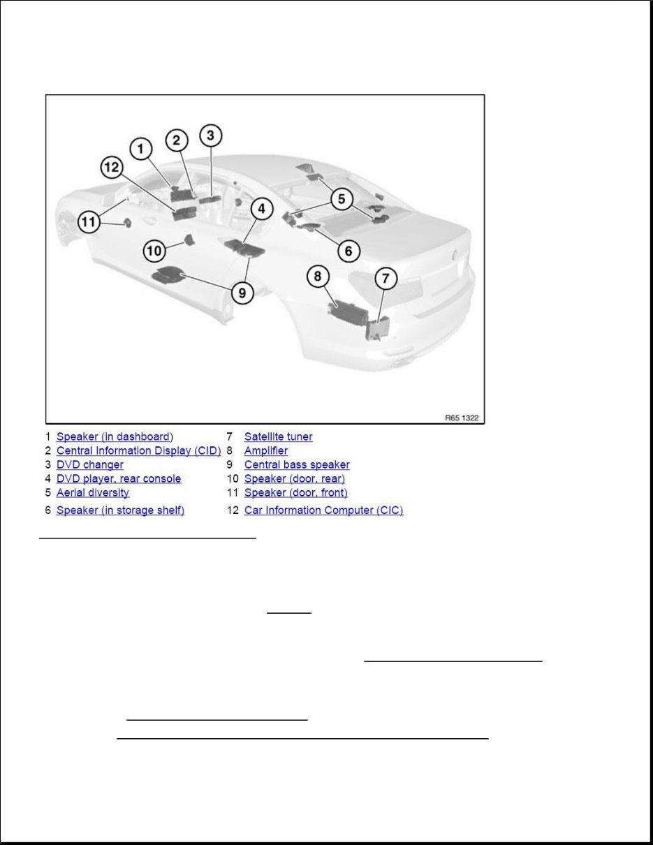
Fig. 7: Identifying Head Unit And Connections Courtesy of BMW OF NORTH AMERICA, INC. Only for US models with satellite radio: When replacing the head unit, additional work is required! Refer to REMOVING AND INSTALLING/REPLACING SATELLITE TUNER (ONLY FOR US MODELS STARTING AT 09/2009) . Replacement: Carry out VEHICLE PROGRAMMING AND ENCODING . 65 00.. OVERVIEW OF AUDIO COMPONENTS
Fig. 8: Overview Of Audio Components Courtesy of BMW OF NORTH AMERICA, INC. 65 12 072 REMOVING AND INSTALLING (REPLACING) AMPLIFIER (TOP HIFI SYSTEM) Necessary preliminary work Clamp off NEGATIVE BATTERY CABLE . Remove LUGGAGE COMPARTMENT WHEEL ARCH PANEL ON LEFT . Release screw (1). IMPORTANT: Read and comply with NOTES on protection against electrostatic discharge (ESD protection). NOTE: Comply with notes and instructions on HANDLING OPTICAL FIBRES .
Remove amplifier (2) in direction of arrow from holder (3). Unlock plug connections and disconnect. Fig. 9: Identifying Screw, Amplifier And Holder Courtesy of BMW OF NORTH AMERICA, INC. Install cable jumper consisting of socket (1) (BMW Parts Service 6901844) and wire jumper (2) in connector (3). Create wire jumper (2) from wire (cross-section 0.75 mm 2 ) and two stops (BMW Parts Service 1393724). Then connect pins 1 and 2 in socket (1) with wire jumper (2). NOTE: Until 09/2009 a Top Hifi amplifier with a different pin assignment is installed!
Get your hands on the 2009 BMW 7-SERIES F02 Service and Repair Manual, your go-to resource for fixing vehicle issues. Whether you're a professional mechanic or a DIY enthusiast, these auto repair manuals provide comprehensive instructions and procedures to tackle various car problems. The manual includes technical data, diagrams, a complete list of car parts, and images, making it suitable for both novice and experienced car mechanics. It covers maintenance, engine, control system, mechanical, fuel service specifications, emission control, and much more. The manual is available in .PDF format and is compatible with Windows and Mac operating systems. With this manual, you can save time, stay updated, and enhance your car repair knowledge. It's a valuable resource that allows you to carry the information with you and work on your vehicle at your convenience.
Comprehensive instructions and procedures for vehicle repair
Suitable for professional mechanics and DIY enthusiasts
Includes technical data, diagrams, and a complete list of car parts
Covers maintenance, engine, control system, and more
Available in .PDF format and compatible with Windows and Mac