

2003-2010 BMW 5 Series E60 E61 Service & Repair Manual
What's Included?
Fast Download Speeds
Online & Offline Access
Access PDF Contents & Bookmarks
Full Search Facility
Print one or all pages of your manual
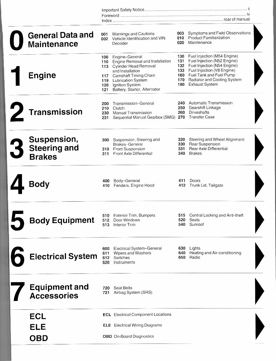
Important Safety Notice i i
Foreword i v
Index rea r of manual
0
General Data and
Maintenance
001 Warning s and Cautions 00 3
002 Vehicl e Identification and VIN 01 0
Decoder 02 0
Symptoms and Field Observations
Product Familiarization
Maintenance
1
Engine
100 Engine-Genera l 13 0
110 Engin e Removal and Installation 13 1
113 Cylinde r Head Removal 13 2
and Installation 13 3
117 Camshaf t Timing Chain 16 0
119 Lubricatio n System 17 0
120 Ignitio n System 18 0
121 Battery , Starter, Alternator
Fuel Injection (M54 Engine)
Fuel Injection (N52 Engine)
Fuel Injection (N54 Engine)
Fuel Injection (V8 Engine)
Fuel Tank and Fuel Pump
Radiator and Cooling System
Exhaust System
2
Transmission
200 Transmission-Genera l 24 0
210 Clutc h 25 0
230 Manua l Transmission 26 0
231 Sequentia l Manual Gearbox (SMG) 27 0
Automatic Transmission
Gearshift Linkag e
Driveshafts
Transfer Case
3
Suspension,
Steering and
Brakes
300 Suspension , Steering and
Brakes-General
310 Fron t Suspension
311 Fron t Axle Differential
320 Steerin g and Wheel Alignment
330 Rea r Suspension
331 Rea r Axle Differential
340 Brake s
4
Body
400 Body-Genera l
410 Fenders , Engine Hood
411 Door s
412 Trun k Lid, Tailgate
5
Body Equipment
510 Exterio r Trim, Bumpers
512 Doo r Windows
513 Interio r Trim
515 Centra l Locking and Anti-theft
520 Seat s
540 Sunroo f
6
Electrical System
600 Electrica l System-General
611 Wiper s and Washers
612 Switche s
620 Instrument s
630 Light s
640 Heatin g and Air-conditioning
650 Radi o
7
Equipment an d
Accessories
720 Sea t Belts
721 Airba g System (SRS)
ECL
ELE
OBD
ECL Electrica l Component Locations
ELE Electrica l Wiring Diagrams
OBD On-Boar d Diagnostics
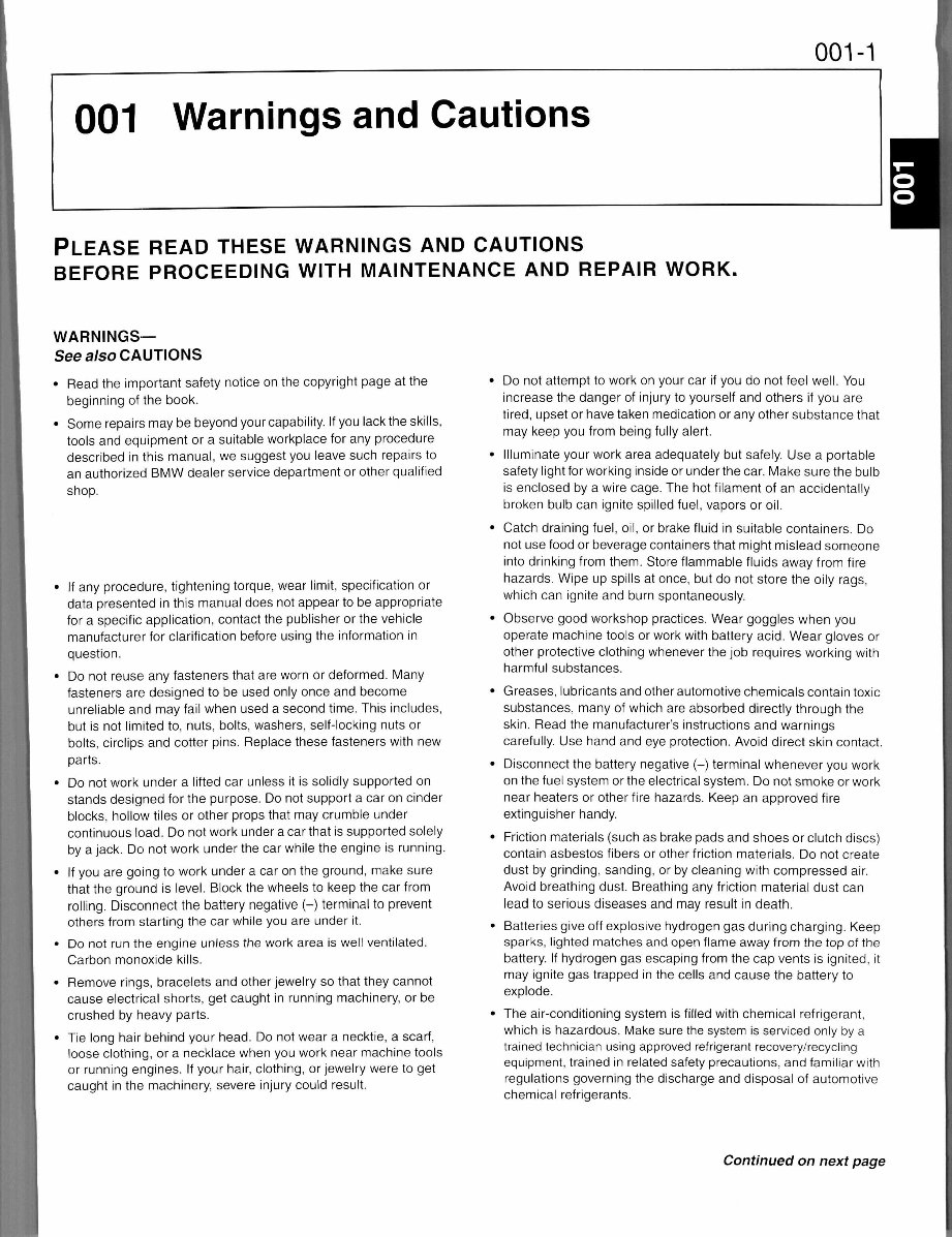
001-1
001 Warnings and Caution s
PLEASE REA D THES E WARNING S AND CAUTION S
BEFORE PROCEEDIN G WIT H MAINTENANC E AN D REPAI R WORK .
WARNINGS—
See also CAUTIONS
• Rea d the important safet y notic e on the copyright page a t the
beginning of the book .
• Som e repairs may be beyond your capability. If you lack the skills,
tools and equipment o r a suitable workplace for any procedure
described in this manual, we suggest you leave such repair s to
an authorized BM W dealer service department or other qualified
shop.
• I f any procedure, tightenin g torque , wear limit, specification or
data presented in this manua l doe s not appear to be appropriate
for a specific application, contac t the publisher or the vehicle
manufacturer for clarification before using the informatio n in
question.
• D o not reuse an y fasteners that are worn or deformed. Man y
fasteners are designed to be used only once and become
unreliable and may fail when used a second time. This includes ,
but is not limited to, nuts, bolts, washers, self-locking nuts or
bolts, circlips and cotte r pins . Replace these fasteners with new
parts.
• D o not work under a lifted car unless i t is solidly supporte d on
stands designe d fo r the purpose. Do not support a car on cinder
blocks, hollow tile s or other prop s that may crumble unde r
continuous load . Do not work unde r a car that is supported solely
by a jack. Do not work unde r the car while the engine is running.
• I f you are going to work under a car on the ground, mak e sure
that the ground is level. Block the wheels to keep the car from
rolling. Disconnec t th e battery negative (-) termina l to prevent
others from starting the car while you are unde r it.
• D o not run the engin e unles s th e work area is well ventilated.
Carbon monoxide kills.
• Remov e rings , bracelet s and other jewelry so that they canno t
cause electrical shorts, get caught in running machinery, or be
crushed by heavy parts .
• Tie long hai r behin d you r head . Do not wear a necktie, a scarf,
loose clothing, or a necklace when you work near machine tool s
or runnin g engines. If your hair, clothing, or jewelry were to ge t
caught i n the machinery , sever e injury could result .
Do not attempt to work on your car i f you d o no t feel well. You
increase the dange r of injury to yourself and other s i f you ar e
tired, upset or have taken medication or any other substance tha t
may keep you from being fully alert.
Illuminate your work area adequately but safely. Use a portabl e
safety light for working inside or under the car. Make sure the bul b
is enclosed b y a wire cage. The ho t filament of an accidentall y
broken bul b ca n ignite spilled fuel, vapors or oil.
Catch draining fuel , oil, or brake fluid in suitable containers . Do
not use food or beverage containers that might mislead someon e
into drinking from them. Store flammable fluids away from fire
hazards. Wip e up spills at once, but do not store the oil y rags ,
which can ignit e and burn spontaneously.
Observe good workshop practices. Wear goggles whe n you
operate machine tool s or work with battery acid. Wea r glove s or
other protective clothing whenever the job requires working with
harmful substances .
Greases, lubricants and other automotive chemicals contain toxic
substances, many of which are absorbed directly throug h the
skin. Rea d the manufacturer's instructions and warning s
carefully. Use hand and eye protection. Avoid direct skin contact.
Disconnect the battery negativ e (-) termina l whenever yo u work
on the fuel system or the electrical system. D o not smoke or work
near heaters or other fire hazards . Kee p an approved fir e
extinguisher handy .
Friction materials (such as brake pads and shoes or clutch discs)
contain asbestos fibers or other friction materials . D o not create
dust by grinding, sanding , or by cleaning wit h compressed air.
Avoid breathing dust . Breathing any friction material dus t ca n
lead to serious diseases and may result in death.
Batteries give off explosive hydrogen gas during charging. Keep
sparks, lighted matche s an d open flame away from the top of the
battery. If hydrogen gas escaping from the cap vents is ignited, it
may ignite gas trapped in the cells and cause the battery to
explode.
The air-conditioning system is filled with chemical refrigerant ,
which is hazardous. Mak e sure the system is serviced only by a
trained technician using approved refrigerant recovery/recyclin g
equipment, trained in related safety precautions, and familiar with
regulations governing the discharge and disposal of automotive
chemical refrigerants.
Continued on next page
• Thoroughl y read each procedur e and the WARNINGS and
CXcXCxzcxz
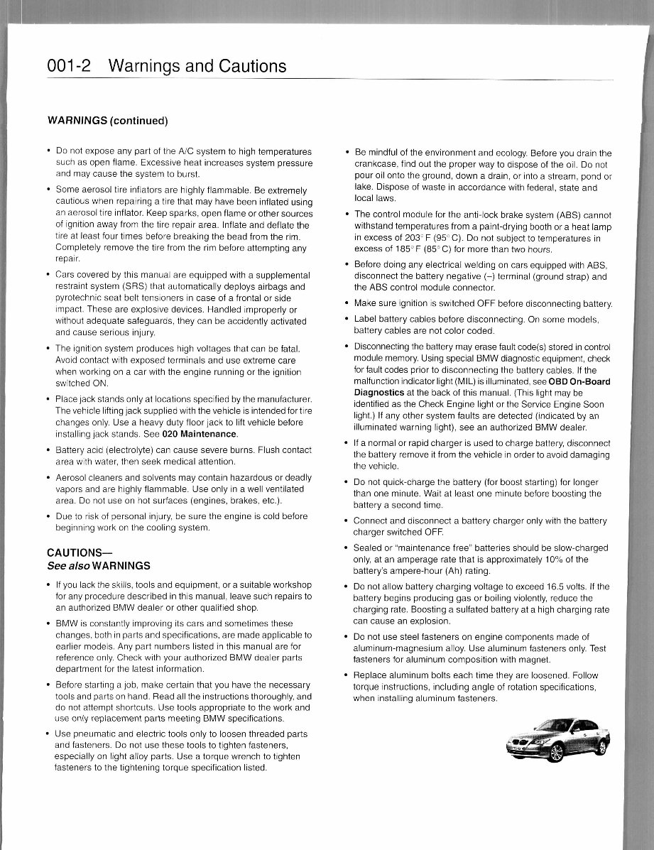
001-2 Warning s and Cautions
WARNINGS (continued )
• D o not expose any par t o f the A/C system to high temperature s
such as open flame. Excessiv e heat increase s syste m pressure
and may cause th e system to burst.
• Som e aerosol tire inflators are highly flammable. Be extremely
cautious when repairin g a tire that may have been inflate d usin g
an aerosol tire inflator. Keep sparks, open flame or other sources
of ignition away from the tire repai r area. Inflat e and deflate the
tire at least four times befor e breaking th e bead from the rim .
Completely remov e the tire from the ri m before attempting an y
repair.
• Car s covered by this manua l ar e equipped wit h a supplementa l
restraint system (SRS ) that automaticall y deploy s airbag s an d
pyrotechnic seat bel t tensioner s in case o f a frontal or side
impact. These ar e explosive devices. Handle d improperly or
without adequate safeguards , the y can be accidently activate d
and cause seriou s injury .
• Th e ignition system produce s hig h voltage s tha t can be fatal.
Avoid contact with exposed terminals an d us e extreme car e
when working on a car with the engine runnin g o r the ignitio n
switched ON.
• Plac e jack stands only at locations specified by the manufacturer.
The vehicle lifting jack supplied with the vehicle is intended for tire
changes only . Use a heavy duty floor jack to lif t vehicle before
installing jack stands . See 020 Maintenance.
• Batter y acid (electrolyte) can cause sever e burns. Flus h contact
area with water, then seek medica l attention .
• Aeroso l cleaners and solvents may contain hazardou s or deadly
vapors and are highly flammable . Us e only i n a well ventilated
area. Do not use on hot surfaces (engines , brakes , etc.).
• Du e to risk of personal injury , be sure the engine is cold before
beginning work on the cooling system .
CAUTIONS—
See also WARNINGS
• I f you lack the skills, tools and equipment, o r a suitable workshop
for any procedure described in this manual, leave such repairs to
an authorized BMW dealer or other qualified shop.
• BM W is constantly improving it s cars and sometimes these
changes, bot h in parts and specifications, are made applicable to
earlier models . Any part numbers liste d in this manua l ar e for
reference only. Check with your authorized BMW dealer parts
department for the latest information.
• Befor e starting a job, mak e certai n tha t you hav e the necessary
tools and parts on hand. Read all the instructions thoroughly, and
do not attempt shortcuts. Use tools appropriate t o the work and
use only replacement parts meeting BMW specifications.
• Us e pneumatic an d electric tools onl y to loosen threade d parts
and fasteners. Do not use these tool s to tighten fasteners,
especially on light alloy parts . Us e a torque wrench to tighten
fasteners to the tightening torqu e specification listed.
Be mindful of the environment an d ecology. Before you drain the
crankcase, fin d out the prope r wa y to dispose of the oil. D o not
pour oil onto the ground , dow n a drain, or into a stream, pon d or
lake. Dispos e of waste in accordance wit h federal, state an d
local laws .
The control module for the anti-lock brak e system (ABS) canno t
withstand temperatures from a paint-drying booth or a heat lam p
in excess of 203° F (95° C). D o not subject to temperatures in
excess of 185°F (85° C) for more than two hours .
Before doing an y electrical welding on cars equipped with ABS,
disconnect the battery negativ e (- ) termina l (groun d strap) and
the ABS control modul e connector .
Make sur e ignition is switched OFF befor e disconnecting battery.
Label batter y cables befor e disconnecting. On some models ,
battery cables are not color coded .
Disconnecting th e battery may erase fault code(s) stored in control
module memory. Usin g special BMW diagnostic equipment, check
for fault codes prior to disconnecting th e batter y cables. If the
malfunction indicator light (MIL) is illuminated, see OBD On-Boar d
Diagnostics at the bac k of this manual. (This light may be
identified as the Check Engin e ligh t or the Service Engin e Soon
light.) I f any othe r syste m fault s ar e detecte d (indicated by a n
illuminated warning light), see an authorized BM W dealer .
If a normal or rapid charger is used to charge battery, disconnec t
the battery remov e it from the vehicle in order to avoid damagin g
the vehicle.
Do not quick-charge the batter y (fo r boost starting) for longe r
than one minute . Wai t at least on e minut e befor e boosting the
battery a second time .
Connect an d disconnect a battery charger only with the battery
charger switched OFF.
Sealed or "maintenance free " batteries shoul d be slow-charged
only, at an amperage rat e that is approximately 10 % of the
battery's ampere-hour (Ah ) rating .
Do not allow battery charging voltag e to exceed 16.5 volts. If the
battery begins producin g ga s o r boiling violently, reduce the
charging rate . Boosting a sulfated battery a t a high charging rat e
can cause an explosion.
Do not use steel fasteners on engine components mad e of
aluminum-magnesium alloy . Use aluminum fasteners only. Test
fasteners for aluminum compositio n wit h magnet.
Replace aluminu m bolt s each time they are loosened. Follo w
torque instructions, including angl e of rotation specifications,
when installin g aluminum fasteners .
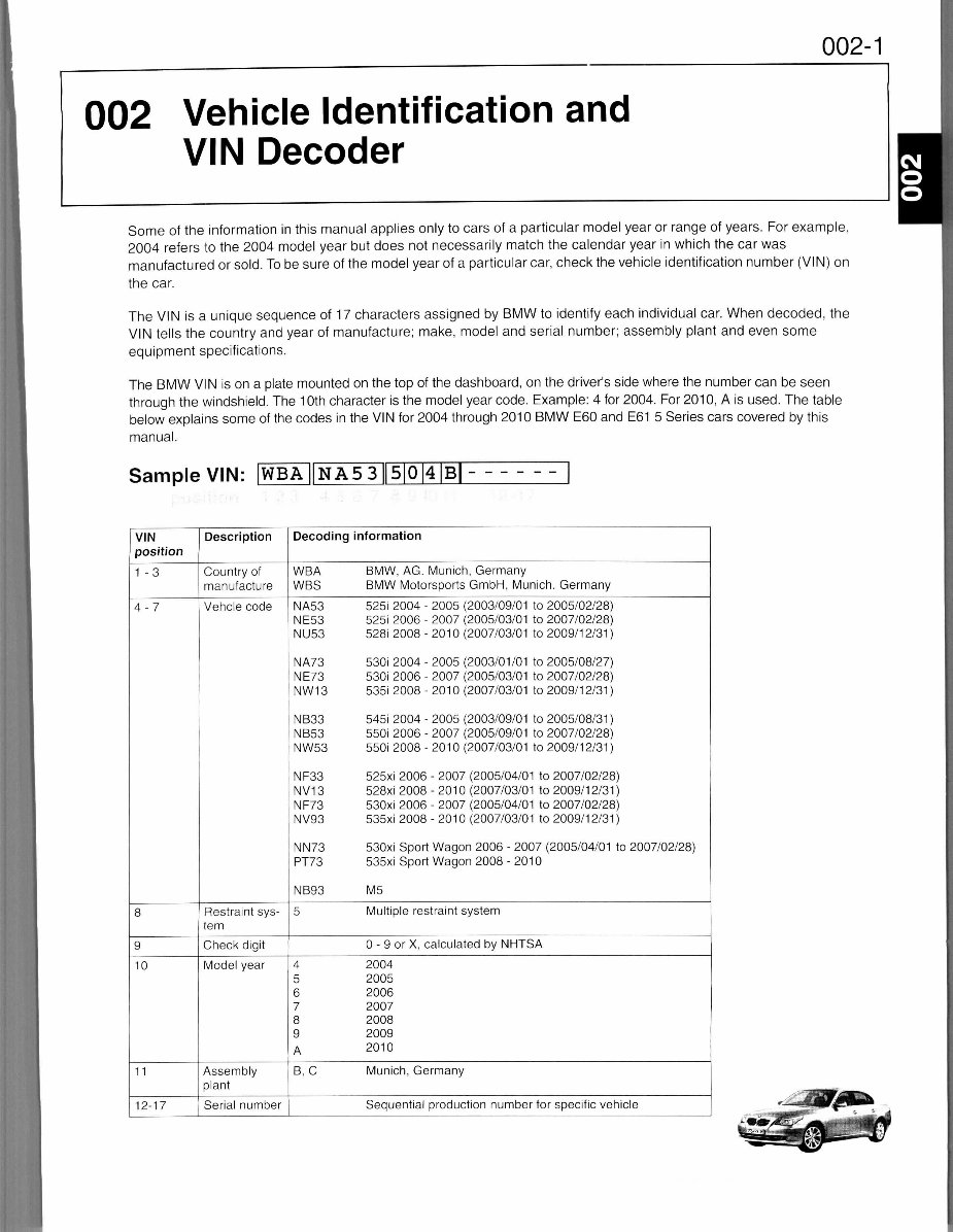
002-1
002 Vehicl e Identification and
VIN Decode r
Some o f the informatio n in this manual applie s onl y to cars of a particular model year or range of years. For example,
2004 refers to the 2004 model year but does not necessarily matc h the calendar yea r in which the car was
manufactured or sold. To be sure of the model year of a particular car, check the vehicle identification number (VIN) on
the car.
The VI N i s a unique sequence of 17 characters assigned by BMW to identify each individual car. When decoded, the
VIN tells the country and year of manufacture; make, mode l and serial number; assembl y plant an d even some
equipment specifications.
The BM W VI N i s on a plate mounted on the top of the dashboard, on the driver's side where the number can be seen
through the windshield. The 10t h character is the model year code. Example: 4 for 2004. For 2010, A is used. The tabl e
below explains some of the codes in the VIN for 2004 through 2010 BMW E6 0 and E6 1 5 Series cars covered by this
manual.
Sample VIN: [WBA||NA53||5|0|4|B|
VIN
position
1 -3
4-7
8
9
10
11
12-17
Description
Country of
manufacture
Vehcle code
Restraint sys-
tem
Check digit
Model year
Assembly
plant
Serial number
Decoding
WBA
WBS
NA53
NE53
NU53
NA73
NE73
NW13
NB33
NB53
NW53
NF33
NV13
NF73
NV93
NN73
PT73
NB93
5
information
BMW, AC. Munich, Germany
BMW Motorsports GmbH, Munich. Germany
525i 2004 - 2005 (2003/09/0 1 to 2005/02/28)
525i 2006 - 2007 (2005/03/01 to 2007/02/28 )
528i 2008 - 201 0 (2007/03/01 to 2009/1 2/31 )
530i 200 4 - 2005 (2003/01/0 1 to 2005/08/27 )
530i 2006 - 2007 (2005/03/01 to 2007/02/28 )
535i 2008 - 2010 (2007/03/01 to 2009/12/31)
545i 2004 - 2005 (2003/09/01 to 2005/08/31)
550i 2006 - 2007 (2005/09/0 1 to 2007/02/28)
550i 2008 - 2010 (2007/03/01 to 2009/12/31)
525xi 2006 - 2007 (2005/04/0 1 to 2007/02/28 )
528xi 2008 - 2010 (2007/03/01 to 2009/12/31)
530xi 2006 - 2007 (2005/04/01 to 2007/02/28)
535xi 2008 - 2010 (2007/03/01 to 2009/12/31)
530xi Spor t Wagon 200 6 - 2007 (2005/04/01 to 2007/02/28)
535xi Sport Wagon 2008 - 201 0
M5
Multiple restraint system
0 - 9 or X, calculated by NHTS A
4
5
6
7
8
9
A
B, C
2004
2005
2006
2007
2008
2009
2010
Munich, Germany
Sequential production number for specific vehicle

003-1
003 Symptom s and Field Observations
GENERAL 003- 1
0 GENERA L DAT A AN D MAINTENANCE 003- 2
1 ENGIN E 003- 5
2 TRANSMISSIO N 003-1 2
3 SUSPENSION , STEERIN G AN D BRAKES. . 003-1 4
4 BOD Y
5 BOD Y EQUIPMEN T
6 ELECTRICA L SYSTE M
7 EQUIPMEN T AND ACCESSORIES .
003-17
003-18
003-19
003-24
GENERAL
This repair group includes a list of symptoms, field observations, and
suggested fixes for common problem s and issues found on BMW 5
Series (E60, E61) vehicles.
The information is organized by sections that correspond t o th e
layout of the repair manual. Additional information (when available)
can be found in the repair group associated with the specifi c issue :
• 0 Genera l Dat a and Maintenance
• 1 Engin e
• 2 Transmission
• 3 Suspension , Steering and Brakes
• 4 Bod y
• 5 Bod y Equipmen t
• 6 Electrica l System
• 7 Equipmen t and Accessories
This information was developed from varied sources, rangin g from
professional BMW technician feedback to manufacturer-issue d
technical service bulletins (TSBs). The content is intended to
complement the repair information found in this repai r manual .
CAUTION—
• The information contained in this section is inherently dated
material. It was applicable and relevant at the time this manual
went to press. A/ways check BMW factory repair information at
www.bmwtechinfo.com or the publisher's website at
www. com for information that may
supersede any information included in this section.
003-2 Symptom s and Fiel d Observations
0 GENERA L DAT A AND MAINTENANCE
Topic Notes
Exiting a vehicle tha t is double-
locked from the outsid e
Never lock a vehicle from outside the car with an someone insid e the
car!
In the unlikely that someon e get s double-locke d insid e th e car , the
person insid e the car can exit the vehicle using the following 2-step
procedure:
• Pres s the central unloc k butto n to disable "double-lock" .
• Pul l the door handl e twic e to open door .
NOTE—
• For vehicles with the factory alarm, opening the door will
activate the alarm.
Additional
information
(when available)
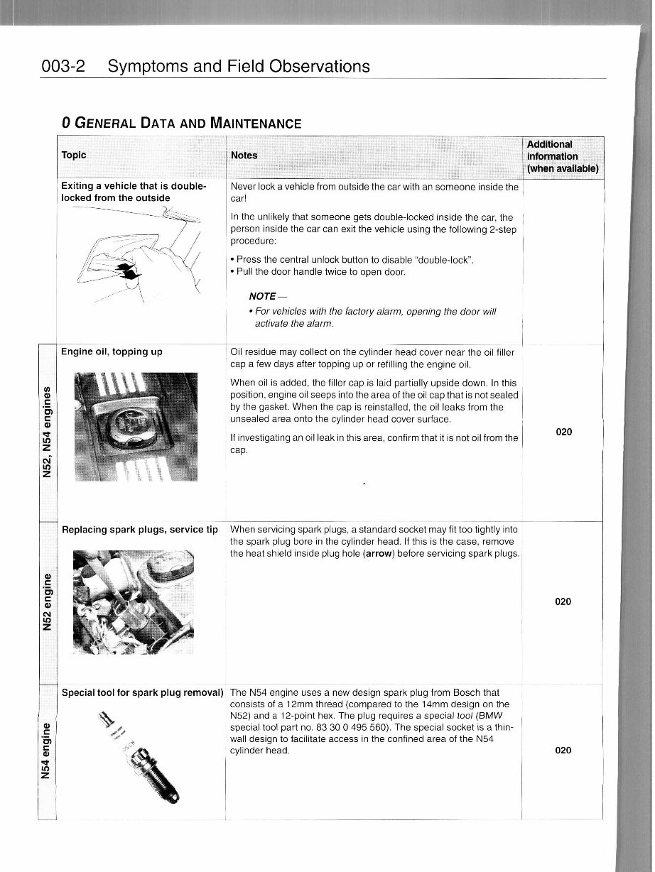
Engine oil , toppin g up
Replacing spark plugs, servic e ti p
Oil residu e ma y collect on the cylinder hea d cove r near th e oi l filler
cap a few days afte r topping u p or refilling the engine oil .
When oi l i s added, th e filler cap is laid partially upsid e down . In this
position, engine oil seeps into the area of the oil cap that is not seale d
by the gasket. When the cap is reinstalled, the oil leaks fro m the
unsealed are a onto the cylinder head cove r surface.
If investigating an oil leak in this area, confirm that it is not oil from the
cap.
020
When servicing spark plugs, a standard socket may fit too tightly into
the spar k plu g bor e i n the cylinder head . If this i s the case , remov e
the hea t shield insid e plu g hole (arrow) before servicing spark plugs .
020
Special tool for spark plu g removal ) Th e N5 4 engine use s a new design spar k plu g from Bosch tha t
consists of a 12m m thread (compared to the 14m m design on the
N52) an d a 12-point hex. The plug require s a special too l (BM W
special tool part no . 83 30 0 495 560). The specia l socke t i s a thin-
wall design to facilitate acces s i n the confined are a o f the N5 4
cylinder head . 020
Symptoms and Field Observations 003- 3
0 GENERA L DAT A AN D MAINTENANCE (CONTINUED )
CD
§
CM
2
o
•a
o
Topic
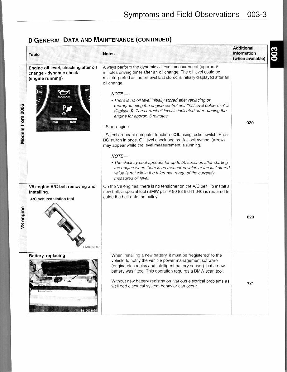
Engine oil level, checking after oil
change - dynamic chec k
(engine running)
V8 engine A/C belt removin g and
installing.
A/C belt installatio n tool
Notes
Always perform the dynamic oil level measurement (approx . 5
minutes driving time) after an oil change. The oil level could be
misinterpreted as the oil level last stored is initially displayed after an
oil change.
NOTE—
• There is no oil level initially stored after replacing or
reprogramming the engine control unit ("Oil level below min" is
displayed). The correct oil level is indicated after running the
engine for approx. 5 minutes.
- Star t engine.
- Select on-board computer function - OIL usin g rocker switch. Press
BC switch in once. Oil level check begins . A clock symbol (arrow)
may appear while the leve l measurement is running.
NOTE—
• The clock symbol appears for up to 50 seconds after starting
the engine when there is no measured value or the last stored
value is not within the tolerance range of the currently
measured oil level.
Additional
information
(when available)
On the V8 engines, there is no tensioner on the A/C belt. To install a
new belt, a special tool (BMW part # 90 88 6 641 040) is required to
guide the belt onto the pulley.
When installing a new battery, it must be "registered" to the
vehicle to notify the vehicle power management software
(engine electronics and intelligent battery sensor) that a new
battery was fitted. This operatio n require s a BMW scan tool.
Without new battery registration, various electrical problems as
well odd electrical system behavior can occur.
020
020
121
003-4 Symptom s and Field Observations
0 GENERA L DAT A AND MAINTENANCE (CONTINUED )
Topic
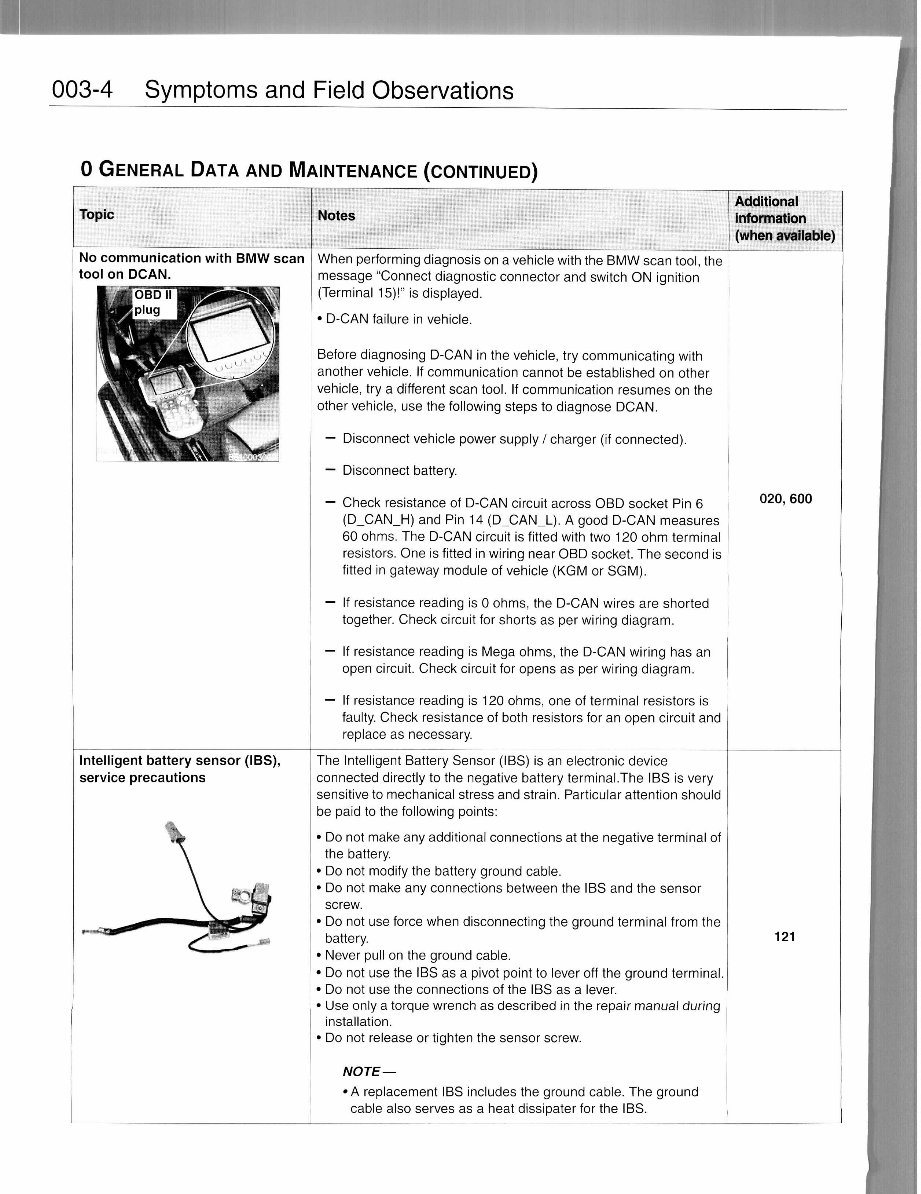
No communication wit h BMW sca n
tool on DCAN . __
plug
Notes
Additional
information
(when available)
Intelligent battery sensor (IBS) ,
service precaution s
When performing diagnosis o n a vehicle with the BMW scan tool, the
message "Connec t diagnostic connecto r and switch ON ignitio n
(Terminal 15)! " is displayed .
• D-CA N failure in vehicle.
Before diagnosing D-CA N in the vehicle, try communicating wit h
another vehicle . If communication cannot be established on othe r
vehicle, try a different scan tool. If communication resume s o n the
other vehicle, us e the following steps to diagnose DCAN .
— Disconnec t vehicl e powe r supply / charger (if connected) .
— Disconnec t battery.
— Chec k resistanc e of D-CAN circuit across OBD socke t Pi n 6
(D_CAN_H) an d Pi n 1 4 (D_CAN__L). A good D-CA N measure s
60 ohms. The D-CAN circui t is fitted with two 12 0 ohm terminal
resistors. One is fitted in wiring near OBD socket. The secon d is
fitted in gateway module of vehicle (KG M or SGM) .
— If resistance reading is 0 ohms, the D-CA N wires are shorte d
together. Check circui t for shorts as per wiring diagram.
— If resistance reading is Mega ohms , the D-CA N wiring ha s a n
open circuit. Check circuit for opens as per wiring diagram .
— If resistance reading is 12 0 ohms, on e o f terminal resistor s is
faulty. Check resistanc e of both resistor s for an open circui t and
replace as necessary .
The Intelligen t Battery Senso r (IBS ) is an electronic devic e
connected directly to the negative battery terminal.The IBS is very
sensitive to mechanical stres s and strain. Particular attention shoul d
be paid to the following points:
• D o not make any additional connections at the negative terminal of
the battery .
• Do not modify the battery groun d cable.
• D o not make any connections between the IBS and the senso r
screw.
• D o not use force when disconnectin g the ground terminal from the
battery.
• Neve r pul l on the ground cable.
• D o not use the IB S as a pivot poin t to lever off the ground terminal .
• D o not use the connections o f the IB S as a lever.
• Us e only a torque wrench as described in the repair manua l during
installation.
• Do not release or tighten the sensor screw .
NOTE—
•A replacemen t IBS includes the ground cable. The groun d
cable als o serves as a heat dissipate r for the IBS .
020, 600
121
Symptoms and Field Observations 003- 5
1 ENGIN E
Topic
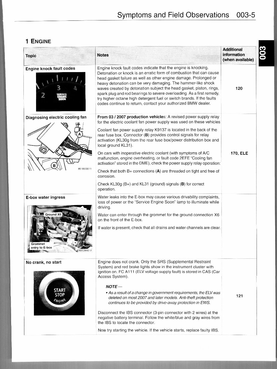
Engine knoc k fault code s
Diagnosing electri c cooling fan
E-box water ingres s
No crank, no start
Notes
Engine knoc k fault codes indicat e tha t the engin e is knocking .
Detonation or knock i s an erratic form of combustion that can cause
head gasket failure as well as other engine damage. Prolonge d or
heavy detonation can be very damaging. Th e hammer-lik e shock
waves created by detonation subject the hea d gasket, piston, rings,
spark plug and rod bearings to severe overloading. As a first remedy,
try highe r octan e hig h detergent fuel or switch brands . I f the faults
codes continue to return, contact your authorized BMW dealer.
Additional
information
(when available)
From 03 / 2007 production vehicles : A revised power supply rela y
for the electric coolant fan power supply was use d on these vehicle s
Coolant fa n powe r supply rela y K9137 is located i n the bac k of the
rear fuse box. Connector (B ) provides control signals for rela y
activation (KLSO g from the rea r fuse box/power distribution box and
local ground KL31).
On cars with inoperative electri c coolant (wit h symptoms of A/C
malfunction, engine overheating, or fault code 2EFE "Cooling fan
activation" stored in the DME), check the power supply relay operation:
Check that both B+ connections (A) are threaded on tight and free of
corrosion.
Check KLSO g (B+) an d KL31 (ground ) signals (B) for correc t
operation.
Water leak s into the E-box may cause variou s drivability complaints,
loss of power or the "Service Engine Soon " lam p to illuminate while
driving.
Water can enter through the grommet for the ground connection X6
on the front of the E-box.
If water is present, check that all drains and water channels are clear.
Engine doe s not crank. Only the SRS (Supplemental Restraint
System) an d re d brake lights show i n the instrumen t cluster with
ignition on. FC A111 (ELV voltage supply fault) is stored in CAS (Ca r
Access System).
NOTE—
•Asa result of a change in government requirements, the ELV was
deleted on most 2007 and later models. Anti-theft protection
continues to be provided by drive-away protection in EWS.
Disconnect th e IB S connector (3-pi n connecto r with 2 wires) at the
negative battery terminal. Follo w the white/blue and gray wires from
the IB S to locate the connector .
Now try startin g the vehicle. I f the vehicle starts, replace faulty IBS .
120
170, EL E
121
You're Reading a Preview
What's Included?
Fast Download Speeds
Online & Offline Access
Access PDF Contents & Bookmarks
Full Search Facility
Print one or all pages of your manual
$31.99
Viewed 87 Times Today


Secure transaction
What's Included?
Fast Download Speeds
Online & Offline Access
Access PDF Contents & Bookmarks
Full Search Facility
Print one or all pages of your manual
$31.99
The BMW 5 Series E60 E61 2003-2010 Factory Service Repair Manual is a comprehensive guide suitable for both professional mechanics and DIY enthusiasts. It covers the BMW 5 Series models from 2003 to 2010, including the E60 and E61 variations, providing step-by-step instructions and illustrations for proper maintenance, repair, and servicing.
Key features of this Factory Service Repair Manual:
- Detailed information on engine, transmission, suspension, electrical system, and more
- Comprehensive instructions for routine maintenance tasks, such as oil changes and brake pad replacement
- Troubleshooting and diagnostic procedures for identifying and resolving common issues
- Detailed wiring diagrams, exploded views, and technical specifications for easy reference
- Written and designed by BMW experts to ensure accuracy and reliability
Whether you are a DIY enthusiast or a professional technician, this Factory Service Repair Manual is an indispensable tool for ensuring the longevity and performance of your BMW 5 Series. Invest in this manual today and unleash the full potential of your vehicle.


