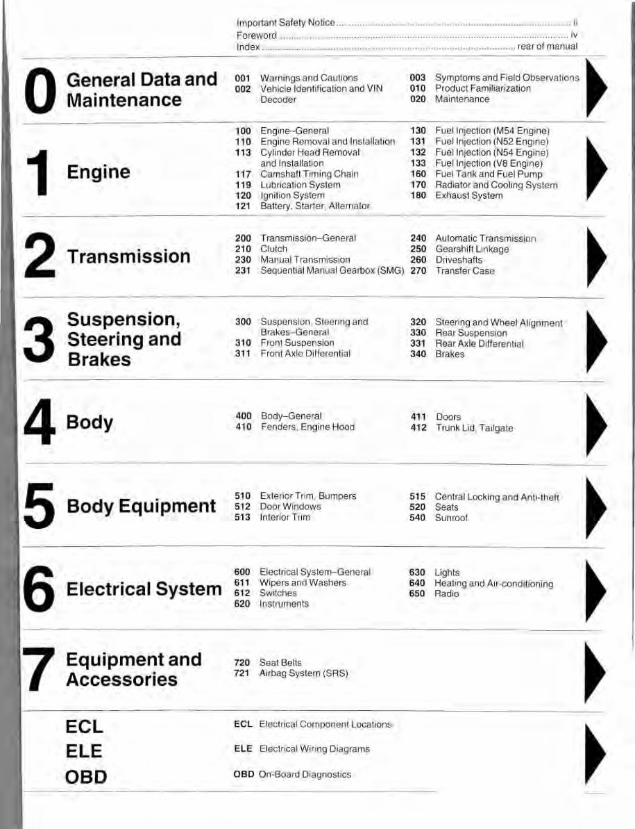
Important Safety Notice ......................................................................................... ii Foreword ............................................. .. ..... .. ........... .. ...... .. .... .. ....... .. ................... iv Index .. ............................................ .. ........................ .. ...................... rear of manual 0 General Data and 001 Warnings and Cautions 003 Symptoms and fleld ObseNaOons ~ 002 Vehicle Identification and VIN 010 Product Familiarization Maintenance Decoder 020 Maintenance 100 Engine- General 130 Fuel Injection (M54 Engine) 110 Engine Removal and Installation 131 Fuel Injection (N52 Engine) ~ 1 11 3 Cylinder Head Removal 132 Fuel Injection (N54 Engine) Engine and Installation 133 Fuel Injection (VB Engine) 117 Camshaft Timing Chain 160 Fuel Tank and Fuel Pump 119 Lubrication System 170 Radiator and Cooling System 120 Ignition System 180 Exhaust System 121 Battery, Starter, Alternator 2 200 Transmission-General 240 Automatic Transmission ~ Transmission 210 Clutch 250 Gearshift Linkage 230 Manual Transmission 260 Driveshafts 231 Sequential Manual Gearbox (SMG) 270 Transfer Case 3 Suspension, 300 Suspension, Steering and 320 Steering and Wheel Alignment ~ Steering and Brakes-General 330 Rear Suspension 310 Front Suspension 331 Rear Axle Differential Brakes 311 Front Axle Differential 340 Brakes 4 Body 400 Body-General 411 Doors ~ 410 Fenders, Engine Hood 412 Trunk Lid, Tailgate 5 Body Equipment 510 Exte ri or Trim, Bumpers 515 Central Locking and Anti-theft ~ 512 Door Windows 520 Seats 513 Interior Trim 540 Sunroof 6 600 Electrical System-General 630 Lights ~ Electrical System 611 Wipers and Washers 640 Heating and Air-conditioning 612 Switches 650 Radio 620 Instruments 7 Equipment and 720 Seat Belts ~ Accessories 721 Airbag System (SRS) ECL ECL Electrical Component Locations ~ ELE ELE Electrical Wiring Diagrams OBD OBD On-Board Diagnostics
001-1 001 Warnings and Cautions PLEASE READ THESE WARNINGS AND CAUTIONS BEFORE PROCEEDING WITH MAINTENANCE AND REPAIR WORK. WA RNIN GS- See also CAUTIONS • Read the important safety notice on the copyright page at the beginning of the book. • Some repairs may be beyond your capability. If you lack the skills, tools and equipment or a suitable workplace for any procedure described m this manual, we suggest you leave such repairs to an authorized BMW dealer service department or other qualified shop. • If any procedure. tightening torque. wear limit. specification or data presented in this manual does not appear to be appropriate for a specific application. contact the publisher or the vehicle manufacturer for clarification before using the information 1n question. • Do not reuse any fasteners that are worn or deformed. Many fasteners are designed to be used only once and become unreliable and may fail when used a second time. This includes, but is not li mited to. nuts, bolts. washers, self-locking nuts or bolts, circlips and co tt er pins. Replace these fasteners with new parts. • Do not work under a lifted car unless it is solidly supported on stands designed for the purpose. Do not support a car on cinder blocks. hollow tiles or other props th at may crumble under continuous load . Do not work under a car that is supported solely by a jack. Do not work under the car while the engine is runni ng. • If you are going to work under a car on the ground, make sure that the ground is level. Block the wheels lo keep the car from rolling. Disconnect the battery negative (-) terminal to prevent others from starting the car white you are under 1t. • Do not run the engine unless t he work area is well ventilated. Carbon monoxide kills. • Remove rings. bracelets and other jewelry so that they cannot cause electrical shorts. get caught in running machinery, or be crushed by heavy parts. • Tie long hair behind your head. Do not wear a necktie, a scarf. loose clothing, or a necklace when you work near machine tools or running engines. If your hair. clothing, or jewelry were to get caught 1n the machinery, severe injury could result. • Do not attempt to work on your car if you do not feel well. You increase th e danger of injury to yourself and others if you are tired, upset or have laken medication or any other substance that may keep you from being fully alert. • Illuminate your work area adequately but safely. Use a portable safety light f or working inside or under the car. Make sure the bulb 1s enclosed by a wire cage. The hot filament of an accidentally broken bulb can ignite spilled fuel. vapors or oil. • Catch draining fuel. 011. or brake fluid in suitable containers. Do not use food or beverage containers that might mislead someone into drinking from them. Store flammable fluids away from fire hazards. Wipe up spills at once, but do not store the oily rags, which can ignite and burn spontaneously. • Observe good workshop practices. Wear goggles when you operate machine tools or work with battery acid. Wear gloves or other protective clothing whenever the job requires working with harmful substances. • Greases, lubricants and other automotive chemicals contain toxic substances, many of which are absorbed directly through the ski n. Read the manufacturer's instructions and warnings carefully. Use hand and eye protection. Avoid direct skin contact. • Disconnect the battery negative (-) terminal whenever you work on th e fu el system or the electri cal system . Do not smoke or work near heaters or other fire hazards. Keep an approved fire extinguisher handy. • Friction materials (such as brake pads and shoes or clutch discs) contain asbestos fibers or o ther friction materials. Do not create dust by grinding, sanding, or by cleaning with compressed air. Avoid breathing dust. Breathing any friction material dust can lead to serious diseases and may result in death. • Batteries give off explosive hydrogen gas during charging. Keep sparks. lighted matches and open flame away from the top of the battery. If hydrogen gas escaping from the cap vents is ignited. 11 may ignite gas trapped in the cells and cause the battery to explode. • The air-conditioning system is filled with chemical refrigerant. which is hazardous. Make sure the system is serviced only by a trained technician using approved refrigerant recovery/recycling equipment. trained in related safety precautions. and famil iar with regulations governing the discharge and disposal of automotive chemical refrigerants. Continued on next page
001-2 Warnings and Cautions WARNINGS (cont inued) • Do not expose any part of the A/C system to hi gh temperatures such as open flame. Excessive heat increases system pressure and may cause the system to burst. • Some aerosol tire inflators a re highly flammable. Be extremely cautious when repairing a tire that may have been inflated using an aerosol tire inflater. Keep sparks, open flame or other sources of ignition away from the tire repair area. Inflate and defl ate the tire at least four times before breaking the bead from the ri m. Completely remove the tire from the rim before attempting any repair . • Cars covered by this manual are equipped with a supplemental restraint system (SRS) that automatically deploys airbags and pyrotechnic seat belt tensloners in case of a frontal or si de impact. These are explosive devices. Handled improperly or wi thout adequate safeguards, they can be accidently activated and cause serious injury. • The ignition system produces high voltages t hat can be fatal. Avoid contact with exposed terminals and use extreme care when working on a car with the engine ru nni ng or the ignition switched ON. • Place jack stands only at locations specified by the manufacturer. The vehicle lifting jack suppli ed wi th the vehicle is intended for tire changes only. Use a heavy duty floor jack to li ft vehicle before installing jack stands. See 020 Maint enance. • Battery acid (electrolyte) can cause severe burns. Flush contact area wi th water. then seek medical attention. • Aerosol cleaners and solvents may contain hazardous or deadly vapors and are highly flammable Use only in a well ventilated area. Do not use on hot surfaces (engines, brakes, etc.). • Due to risk of personal injury, be sure the engine is cold before beginning work on the cooling system. CAUTIONS- See also WARNINGS • If you lack the skills, tools and equipment, or a suitable workshop for any procedu re described in this manual, leave such repairs to an authorized BMW deal er or other quali fied shop. • BMW is constantly improving its cars and sometimes these changes, both in parts and specifications, are made applicable to earlier models. Any part numbers listed in this manual are for reference only. Check with your authorized BMW dealer parts department for the latest information. • Before starting a job, make certain that you have the necessary tools and parts on hand. Read all the instructions thoroughly, and do not attempt shortcuts. Use tools appropriate to the work and use only replacernen\ parts meeting BMW specifications. • Use pneumatic and electric tools only to loosen threaded parts and fas teners. Do not use these tools to tighten fasteners, especia ll y on li ght alloy parts. Use a torque wrench to tighten fasteners to the tightening torque specification listed. • Be mindful of the environment and ecology. Before you drain the crankcase, find out the proper way to dispose of the oil. Do not pour oil onto the ground, down a drain, or into a stream, pond or lake. Dispose of waste in accordance wi th federal, state and local laws. • The control module for the anti-lock brake system (ABS) cannot withstand temperatures from a paint-drying booth or a heat lamp in excess of 203° F (95° C). Do not subject to temperatures in excess of 185° F (85° C} fo r more than two hours. • Before doing any electrical welding on cars equipped with ABS, disconnect the battery negative (-) terminal (ground strap} and the ABS control module connector. • Make sure i gnition is switched OFF before disconnecting battery. • Label battery cables before disconnecting. On some models. battery cables are not color coded. • Disconnecting the battery may erase fault code(s) stored in control module memory. Using special BMW diagnostic equipment, check for fault codes prior to disconnecting the battery cables. If the malfunction indicator light (MIL) is illuminated, see 080 On-Board Diagnostics at the back of this manual. (This li ght may be identified as the Check Engine light or the Service Engine Soon light.) If any other system faults are detected (indicated by an illuminated warning light). see an authorized BMW dealer. • If a normal or rapid charger is used to charge battery, disconnect the battery remove it from the vehicle in order to avoid damaging the vehicle. • Do not quick-charge the battery (for boost starting) for longer than one minute. Wait at l east one minute before boosting the battery a second time. • Connect and disconnect a battery charger only wi th the battery charger switched OFF. • Sealed or "maintenance tree" batteries should be slow-charged only, at an amperage rate that is approximately 10% of the battery's ampere-hour (Ah} rating. • Do not all ow battery charging voltage to exceed 16.5 vo lts. If the battery begins producing gas or boiling violently, reduce the charging rate. Boosting a sulfated battery at a high charging rate can cause an explosion. • Do not use steel fasteners on engine components made of aluminum-magnesium alloy. Use aluminum fasteners only. Test fasteners for aluminum composition wi th magnet. • Replace aluminum bolts each time they are loosened. Follow torque instructions, i ncluding angle of rotation specifications, when installing aluminum fasteners.
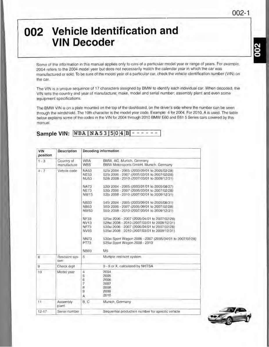
002 Vehicle Identification and VIN Decoder 002-1 Some of the information in this manual applies only to cars of a particular model year or range of years. For example, 2004 refers to the 2004 model year but does not necessarily match the calendar year in which the car was manufactured or sold. To be sure of the model year of a particular car, check the vehicle identification number (VIN) on the car. The VIN is a unique sequence of 17 char acters assigned by BMW to identify each in dividual car. When decoded , the VIN tells the country and year of manufacture: make. model and serial number: assembly plant and even some equipment speci fi cations. The BMW VIN is on a plate mounted on the top of the dashboard, on the driver's side where the number can be seen through the windshield. The 10th character is the model year code. Example: 4 for 2004. For 2010, A is used. The table below explains some of the codes in the VIN for 2004 through 2010 BMW E60 and E61 5 Series cars covered by this manual. Sample VIN: I WBA JI NAS 3 llS IO l4I BI - ----- I VIN Description Decoding information position 1 -3 Country of WBA BMW. AG. Munich, Germany manulacture WBS BMW Motorsports GmbH, Munich. Germany 4-7 Vehcle code NA53 5251 2004 - 2005 (2003/09/01 to 2005/02/28) NE53 525i 2006 - 2007 (2005/03/01 to 2007/02/28) NU53 528i 2008 - 2010 (2007/03/0 1t o2009/ 12/31) NA73 530i 2004 - 2005 (2003/01/01 to 2005/08/27) NE73 530i 2006 - 2007 (2005/03/01 to 2007/02/28) NW1 3 53512008 - 201 o (2007/03/01 to 2009/1 213 1) NB33 545i 2004 - 2005 (2003/09/01 to 2005/08/31) NB53 550i 2006 - 2007 (2005/09/01 to 2007/02/28) NW53 550i 2008 - 2010 (2007/03/01 to 2009/12131) NF33 525xi 2006 - 2007 (2005/04/01 to 2007/ 02/28) NV13 528xi 2008 - 2010 (2007/ 03 / 01to2009 /12/3 1} NF73 530xi 2006 - 2007 (2005/04/ 01 to 2007 / 02/28) NV93 535xi 2008 - 2010 (2007/ 03 /0 1 to 2009/ 12/31) NN73 530xi Sport Wagon 2006 - 2007 (2005/04/01 to 2007/ 02128) PT73 535xi Sport Wagon 2008 - 2010 NB93 MS 8 Restraint sys- 5 Multiple restraint system tern 9 Check digit 0 - 9 or X, calculated by NHTSA 10 Model year 4 2004 5 2005 6 2006 7 2007 8 2008 9 2009 A 2010 11 Assembly B, C Munich, Germany plant 12- 17 Serial number Sequential production number for specific vehicle
003-1 003 Symptoms and Field Observations GENERAL ........... ... ......... ..... .. 003-1 0 GENERAL DATA AND MAINTENANCE ..... 003-2 1 ENGINE ... . .. .. ............. ......... 003-5 2 TRANSMISSION .. ......... .... ........ 003-12 3 SUSPENSION, STEERING AND BRAKES .. 003-1 4 4 BODY ...................... . ...... .. 003-17 5 BODY EQUIPMENT ........ ............ 003-18 6 ELECTRICAL S YSTEM . . . . . . . . . . . . . . . . . 003-19 7 EQUIPMENT AND ACCESSORIES . .... . .. 003-24 GENERAL This repair group includes a list of symptoms, field observations, and suggested fixes for common problems and issues found on BMW 5 Series (E60, E61) vehicles. The information 1s organized by sections that correspond to the layout of the repair manua l. Additional information (when available) can be found in the repair group associated with the specific issue: • o General Data and Maintenance • 1 Engine • 2 Transmission • 3 Suspension, Steering and Brakes • 4 Body • 5 Body Equipment • 6 Electrical System • 7 Equipment and Accessories This information was developed from varied sources, ranging from professional BMW technician feedback to manufacturer-issued technical service bulletins (TSBs). The content is intended to complement the repair information found in this repair manual. CAUTION- • The information contained in this sect i on is inherently dated material. It was applicable a nd relevant at the time this manual went to press. Always check BMW factory repair information at www.bmwtechinfo.com or the publisher's website at www com for information that may supersede any information included in this section.
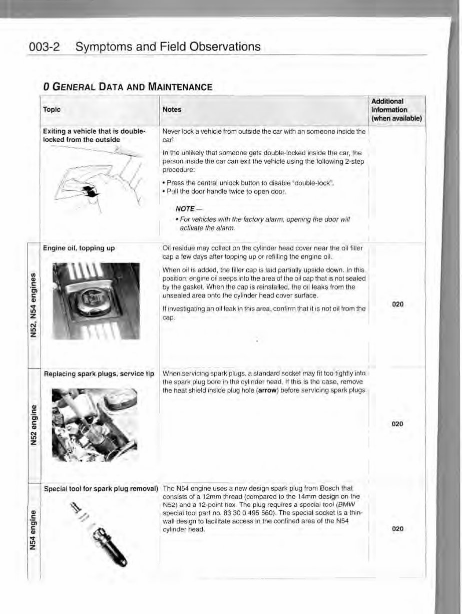
003-2 Symptoms and Field Observations I/I Q) c: en c: Q) o:t" It> z N It> z Q) c: · c, c: Q) 'f:S' It> z 0 GENERAL DATA AND MAINTENANCE Topic Exiting a veh ic le that is double· locked from the out s ide -----. ~- - -.!'··- ; .... -- r-~i-<-1, /[_~-A~ ' l-------~ ( \ Eng ine o il , topping up Notes Never lock a vehicle from outside the car with an someone inside the car! In the unlikely that someone gets double-locked inside the car, the person inside the car can exit th e vehicle using th e following 2-step procedure: I • Press the central unlock button to disable "double-lock". • Pull the door handle twice to open door. NOTE - • For vehicles with the factory alarm, opening the door will activate the alarm. Oil residue may collect on the cylinder head cover near the oil filler cap a few days after topping up or refilling the engine oil. When oil is added, the filler cap is laid partially upside down. In this position. engine oil seeps into the area of the oil cap that is not sealed by the gasket. When the cap is reinstalled. the oil leaks from the unsealed area onto the cylinder head cover surface. If investigating an oil leak in this area, confirm that it 1s not oil from the cap. Replacing spark plug s, service tip When servicing spark plugs, a standard socket may fit too ti ghtly in to Special tool for s park plug removal) th e spark plug bore in th e c yl inder head. II this is the case, remove the heat shield inside plug hole (arrow) before servi ci ng spark plugs. The N54 engine uses a new design spark plug from Bosch that consists of a 12mm thread (compared to the 14mm design on the N52) and a 12-point hex. The plug requires a special tool (BMW special tool part no. 83 30 O 495 560). The special socket is a thin· wall design to facilitate access in the confined area of the N54 cylinder head. Additional information (when available) 020 020
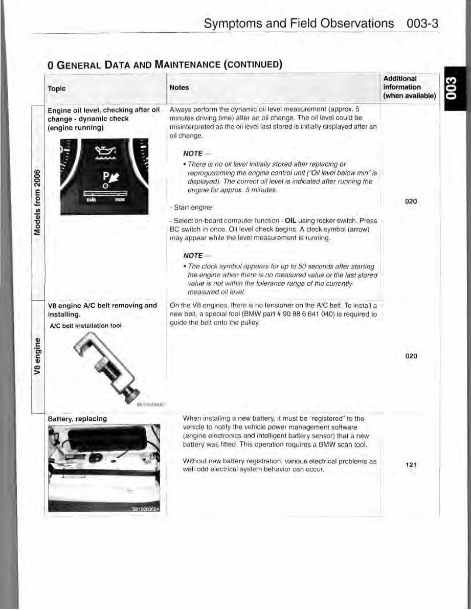
U) 0 0 N E e - "' Q) 'tJ 0 ~ GI c Cl c GI Cl) > Symptoms and Field Observations 003-3 0 GENERAL DATA AND MAINTENANCE (CONTINUED) Topic __ ,,_ I _ N_ ot _e_s _____ _ ~------------~--- Additional information (when available) Engine oil level, checking after oil change - dynamic check (engine running) VS engine A/C belt removing and installi ng. AJC belt installation tool Battery, replacing 0510003-024 Always perform the dynamic oil level measurement (approx. 5 minutes driving time) after an oil change. The oil level could be misinterpreted as the oil level last stored is initially displayed after an oil change. NOTE- • Th ere is no oil level initially stored after replacing or reprogramming the engine control unit ("Oil level below min" is displayed). The correct oil level is indicated after running the engine for approx. 5 minutes. - Start engine. - Select on-board computer function - OIL using rocker switch. Press BC switch in once. Oil level check begins. A clock symbol (arrow) may appear wh ile the level measurement is running. NOTE - • The clock symbol appears for up to 50 seconds after starting the engine when there is no measured value or the last stored value is not within the tolerance range of the currently measured oil level. On the VS engines, there is no tensioner on th e A/C belt. To insta~ new belt, a special tool (BMW part # 90 88 6 641 040} is required to guide the belt onto the pulley. When installing a new battery. it must be "registered" to the vehicle to notify the vehicle power management software (engine electronics and intelligent battery sensor} that a new battery was fitted. This operation requires a BMW scan tool. Without new battery registration, various electrical problems as we ll odd electrical system behavior can occur. 020 020 121
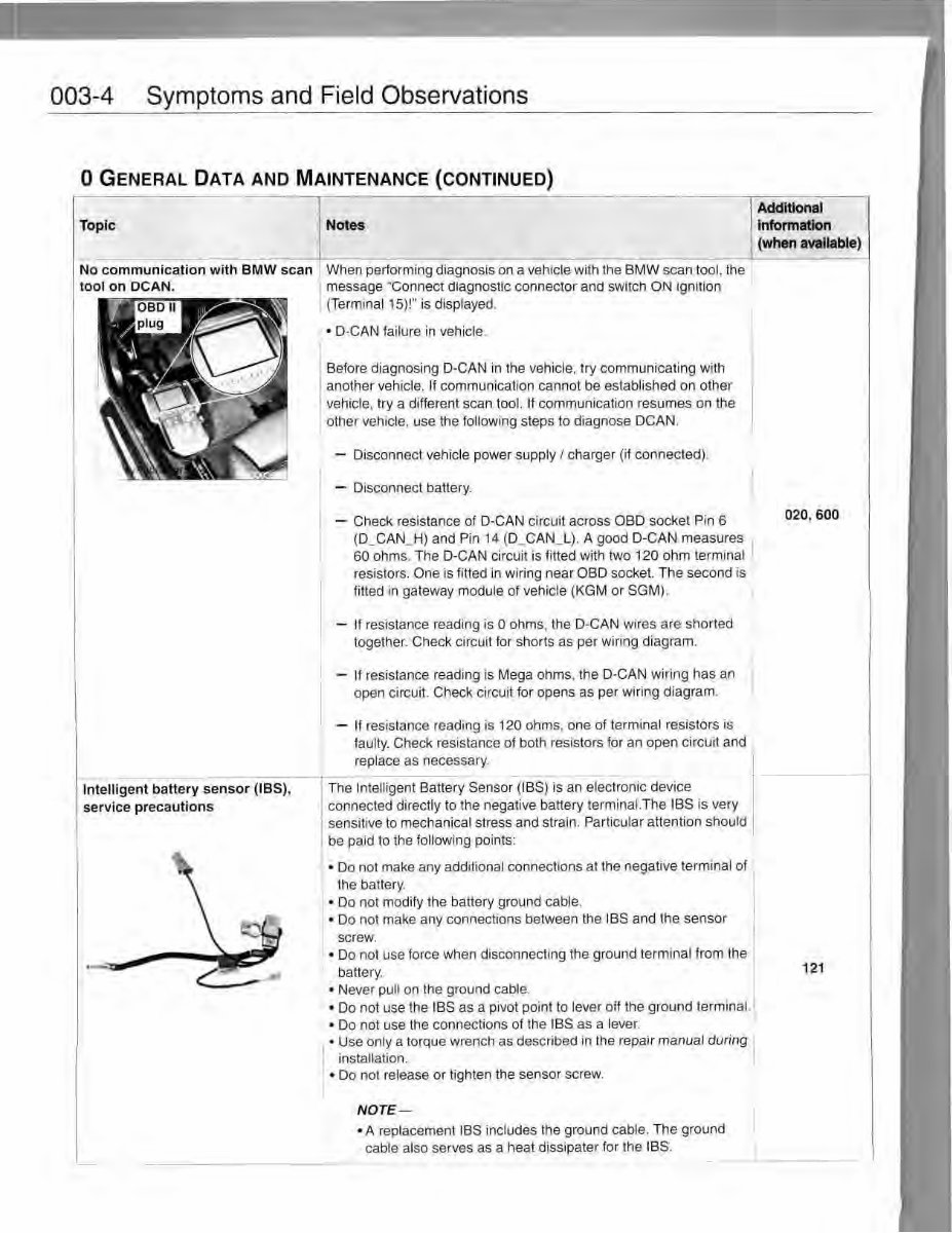
003-4 Symptoms and Field Observations 0 GENERAL DATA AND MAINTENANCE (CONTINUED) I ~~~~~~~~~--.- A - dd -m- .onal ~~~~ Topic Notes information - (when available) Intelligent battery sensor (IBS), serv ice precautions When performing diagnosis on a vehicle with the BMW scan tool, the message "Connect diagnostic connector and switch ON Ignition (Terminal 15)!" is displayed. • D-CAN failure in vehicle. Before diagnosing D-CAN in th e vehicle, try communicating with another vehicle. If communication cannot be established on other vehicle, try a different scan tool. If communication resumes on the other vehicle, use the following steps to diagnose DCAN. - Disconnect vehicle power supply I charger (if connected). - Disconnect battery. - Check resistance of D-CAN circuit across OBD socket Pin 6 (D_CAN_H) and Pin 14 (D_CAN_L). A good D-CAN measures 60 ohms. The D-CAN circuit is fitted with two 120 ohm terminal resistors. One is fitted in wiring near OBD socket. The second is fitted in gateway module of vehicle (KGM or SGM). - If resistance reading is O ohms, the D-CAN wires are shorted together. Check circuit for shorts as per wiring diagram. - If resistance reading is Mega ohms, the D-CAN wiring has an open circuit. Check circuit for opens as per wiring diagram. - If resistance reading is 120 ohms, one of terminal resistors is faulty. Check resistance of both resistors for an open circuit and replace as necessary. The Intelligent Battery Sensor (IBS) is an electronic device connected directly to the negative battery terminal.The IBS is ve ry sensitive to mechanical stress and strain. Particular attention should be paid to the following points: • Do not make any additional connections at the negative terminal of the battery. • Do not modify the battery ground cable. • Do not make any connections between the IBS and the sensor screw. • Do not use force when disconnecting the ground terminal from the battery. • Never pull on the ground cable. • Do not use the IBS as a pivot point to lever off the ground terminal. • Do not use the connections of the IBS as a lever. I • Use only a torque wrench as described in the repair manual during installation. • Do not release or tighten the sensor screw. NOTE - • A replacement I BS includes lhe ground cable. The ground cable also serves as a heat dissipater for the IBS. 020, 600 121
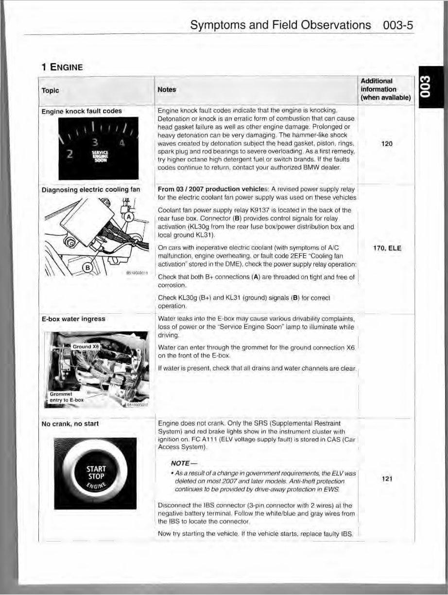
1 ENGINE Topic Engine knock fault codes Diagnosing electric cooling fan E- box water ingress No crank, no start Symptoms and Field Observations 003-5 I Notes I Additional infonnation I (when available) Engine knock fault codes indicate that the engine is knocking. Detonation or knock is an erratic form of combustion that can cause head gasket failure as well as other engine damage. Prolonged or heavy detonation can be very damaging. The hammer-like shock I waves created by detonation subject the head gasket, piston, rings, spark plug and rod bearings to severe overloading. As a first remedy, try higher octane high detergent fuel or switch brands. If the faults I codes continue to return, contact your authorized BMW dealer. From 03 / 2007 production vehicles: A revised power supply relay i- for the electric coolant fan power supply was used on these vehicles Coolant fan power supply relay K9137 is located in the back of the rear fuse box. Connector (B) provides control signals for relay activation (KL30g from the rear fuse box/power distribution box and local ground KL31). 120 On cars with inoperative electric coolant (with symptoms of A/C malfunction, engine overheating. or fault code 2EFE "Cooling fan activation" stored in the DME), check the power supply relay operation: 170, ELE Cheok that both B+ connections (A) are threaded on tight and free of corrosion. Check KL30g (B+) and KL31 (ground) signals (B) for correct operation. Water leaks into the E-box may cause various drivability complaints, loss of power or the .. Service Engine Soon" lamp to illuminate while driving. 1 Water can enter through the grommet for the ground connection X6 on the front of the E-box. If water is present. check that all drains and water channels are clear. I l Engine does not crank. Only the SRS (Supplemental Restraint System) and red brake lights show in the instrument cluster with ignition on. FC A 111 (ELV voltage supply fault) is stored in CAS (Car Access System). NOTE- • As a result of a change in government requirements, the ELV was deleted on most 2007 and later models. Anti-theft protection conlinues to be provided by drive-away protection in EWS. Disconnect the IBS connector (3-pin connector with 2 wires) at the negative battery terminal. Follow the white/blue and gray wires from the IBS to locate the connector. Now try starting the vehicle. If the vehicle starts, replace faulty IBS. I I -- 121
This workshop service manual for the BMW 528i 2007 2008 2009 2010 is designed for use by professional mechanics and DIY enthusiasts. It covers repair and overhaul procedures, including instructions on components manufactured for the BMW 528i 2007 2008 2009 2010. The manual also provides information and procedures for routine maintenance and servicing, as well as diagnostic and repair procedures to follow when trouble occurs.
For those intending to do maintenance and repair on their BMW 528i 2007 2008 2009 2010, it is essential that safety equipment be used and safety precautions observed when working on the vehicle. The manual includes specifications and procedures available in an authorized BMW 528i 2007 2008 2009 2010 dealer service department, and it emphasizes particular information denoted by the wording and symbols: WARNING, CAUTION, NOTE.
It also refers to special tools that are recommended or required to accomplish adjustments or repairs, often identified by their BMW 528i 2007 2008 2009 2010 special tool number and illustrated. The manual aims to help users get the best value from their BMW 528i 2007 2008 2009 2010 and contains all necessary instructions needed for any repair the vehicle may require.
The content of the service manual depicts parts and/or procedures applicable to the particular product at the time of writing. It includes information such as tune-ups, maintenance, removal & install procedures, assemblies & disassemblies, fuel system, ignition, lubrication system, exhaust, electrical system, body, and more extensive repair involving engine and transmission disassembly.
FAST and FREE ELECTRONIC DELIVERY via Email!!! Language: English. Printable: Yes. File Format: .PDF or .OVA (Software).
General Information
Maintenance
Lubrication
Heating
Ventilation
Air Conditioning
Suspension
Front Suspension
Rear Suspension
Wheel
Tire System
Differential
Driveline
Drive Shaft
Transfer Case
Brakes
Engine
Engine Mechanical
Engine Cooling
Engine Fuel
Engine Electrical
Ignition System
Starting
Charging System
Emissions
Engine Exhaust
Engine Lubrication
Engine Speed Control System
Clutch
Cooling
Electronic Control Modules
Engine Systems
Heated Systems
Horn
Ignition Control
Instrument Cluster
Lamps
Power Systems
Restraints
Speed Control
Transmission
Exhaust System
Body Structure
Seats
Security and Locks
Air Bag System
Exterior Trim
Interior Trim
Frame
Bumpers
Fuel System
Steering
Transmission and Transfer Case
Tires
Wheels
Body
Heating
Air Conditioning
Emissions Control
Engine Removal
Engine Installation
Final Drive
Electrical System
Air cleaner element renewal
Air cleaner temperature control check
Auxiliary drivebelt check
Battery electrolyte level check
Battery terminal check
Brake hydraulic fluid renewal
Brake hydraulic system seal and hose renewal
Brake pipe and hose check
Choke adjustment check
Contact breaker point renewal and distributor lubrication