00 GENERAL, TECHNICAL DATA > GENERAL INFORMATION > AUTOMATIC TRANSMISSION > Transmission Design and Function Audi 8-Speed Automatic Transmission 0C8 Transmission Control Module -J217- Installed location: The transmission control module is under the right front seat. Refer to Transmission Control Module -J217- . Shift Point Changes on Inclines and Declines An additional gear change map automatically selects the gear changes for gradients dependent upon accelerator pedal position and driving speed. The gear change map for extreme uphill stretches is matched to engine output The gear change map for extreme downhill stretches is matched to the braking effect of the engine. Direct gear selection by the way of the Tiptronic function permits utilization of engine braking action with a specific gear engaged, for example, on a downhill gradient with a trailer. 00 GENERAL, TECHNICAL DATA > GENERAL INFORMATION > CLEAN WORKING CONDITIONS > Always clean connection places and surrounding areas with engine or brake cleaner before loosening and dry cleaned places. Clean the transmission and transmission components using cleaning solution -D 009 401 04-. Use lint-free cloths when cleaning, for example, the "WYPALL X70/WORKHORSE" cloth made by Kimberly-Clark Professional. Seal all open lines and connections immediately with clean plugs or caps from the engine bung set VAS 6122. Place removed parts on a clean surface and cover. Only use lint-free cloths for this! Carefully cover or plug unpacked components if repairs cannot be performed immediately. Only install clean components: Remove the replacement parts from their packaging just prior to installing them. Protect the disconnected connectors from dirt and moisture and only connect them when they are dry. 00 GENERAL, TECHNICAL DATA > GENERAL INFORMATION > CONTACT CORROSION > Contact corrosion can occur if non-approved fasteners are used such as bolts, nuts, washers, etc.
For this reason, only connecting elements with a special surface coating are installed. In addition, rubber or plastic parts and adhesive are made of materials that do not conduct electricity. If you are not sure about the suitability of parts, install new parts. NOTE: We recommend using original replacement parts only. They have been inspected and are compatible with aluminum. It is recommended to use Audi accessories. Damage resulting from contact corrosion is not covered by the warranty. 00 GENERAL, TECHNICAL DATA > GENERAL INFORMATION > REPAIR INFORMATION > Carefulness, cleanliness and the correct tools are required for transmission repairs to be successful. The usual basic safety precautions also, naturally apply when carrying out vehicle repairs. Some general repair information that applies to several procedures throughout this information is summarized here. They apply to this repair information. Guided Fault Finding, OBD and Test Instruments Determine the cause of the malfunction as accurately as possible using Guided Fault Finding , OBD and Test Instruments before starting any repairs on the automatic transmission using the vehicle diagnostic tester. Oil, Environmental and Disposal Regulations Handle ATF, axle oil and other fluids with care. Dispose of drained ATF properly. Follow the legal environmental and disposal regulations. Follow the information provided on oil packaging. Special Tools and Equipment For a complete list of special tools used in the Repair Information. See ServiceNet under Special Tools and Equipment. Selector Mechanism Emergency Release If the battery has been disconnected or is discharged and the vehicle must be towed or pushed, it will be necessary to push the shift mechanism emergency release to shift the selector lever from "P" to "N". Refer to SELECTOR MECHANISM, PERFORM EMERGENCY RELEASE . Transmission Clean working conditions for the automatic transmission, refer to CLEAN WORKING CONDITIONS . Do not let the engine run or tow the vehicle when the oil pan is removed or when there is no ATF in
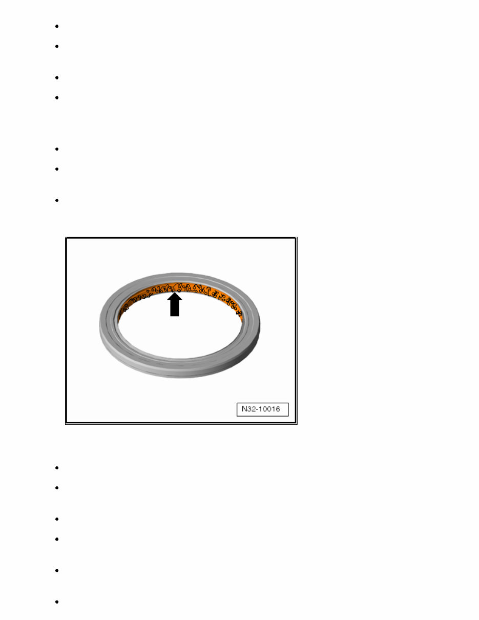
the transmission. With the transmission removed, secure the torque converter so that it cannot fall out. Check installation dimension of torque converter before installing the transmission TORQUE CONVERTER, INSTALLING => Installed Dimension . When installing the transmission, make sure that the alignment bushings are installed correctly. When exchanging automatic transmission or components, all fluid levels should be checked and corrected, if necessary. Likewise, all lines must be cleaned. Capacities, refer to CAPACITIES . Shaft Seals, Sealing Rings, O-rings, Seals O-rings, shaft seals and seals must be replaced. After removing gaskets, examine contact surface on housing/shaft for burr resulting from removal or for other signs of damage. Before installing radial shaft seal, fill the space between sealing lips -arrow- halfway with grease G 052 128 A1. The open side of the seals point toward the fluid to be sealed in. Before installing, lightly lubricate shaft seal outer circumference and sealing lips with ATF or gear oil, depending on installation location. Coat O-rings with ATF before inserting to prevent crushing rings during installation. Always use approved ATF. Other types of lubrication cause faults to occur in the transmission hydraulics. Press in new shaft seal, so that the sealing lip does not run on the same point as the sealing lip of the old shaft seal (use insertion depth tolerances). Replace paper gaskets, thoroughly clean sealing surfaces and completely remove old seals. Fig 1: Identifying Oil Seal Courtesy of AUDI OF AMERICA, LLC
After installing, check the relevant fluid levels and fill if necessary. Capacities CAPACITIES . Bolts and Nuts Loosen bolts in the opposite of tightening sequence if another sequence is not specified. Nuts and bolts which secure covers and housings should be loosened and tightened crosswise in stages if no tightening sequence is specified. The tightening specifications stated apply to non-oiled nuts and bolts. Always replace self-locking nuts and bolts. Use a wire brush to clean the threads of the bolts that were screwed in with locking compound. Install the bolts with locking fluid AMV 185 101 A1. Threaded holes into which self-locking bolts or bolts coated with locking fluid are screwed, must be cleaned (for example tap). Otherwise there is a risk that the bolts will shear the next time they are removed. Circlips Do not overstretch the circlips. Always replace damaged or stretched circlips. The circlips must fit completely inside the groove. Bearings Insert bearing with axle oil or ATF, depending on installation location. Replace the transmission if any of the shift elements are scorched. Control Modules, Electronic Components and Contacts Only touch electrical components after discharging static electricity on a grounded object, for example by touching (skin contact) vehicle or vehicle lift. Connector contacts in electric connectors, control modules and electrical components must not be touched with the hands under any circumstances. They can be destroyed by static discharge. 00 GENERAL, TECHNICAL DATA > GENERAL INFORMATION > SAFETY PRECAUTIONS > TEST DRIVES WITH THE USE OF TEST AND MEASURING DEVICES > If testing equipment must be used during a road test, observe the following: WARNING: Distraction and testing equipment that is not secured properly can cause accidents. The passenger airbag could pose a risk if it deploys in a collision. Operating testing equipment while driving causes it to shift position.
There is an increased risk of injury due to unsecured testing equipment. Always secure testing equipment on the rear seat using a strap and have a second person in the rear seat operate it. 00 GENERAL, TECHNICAL DATA > GENERAL INFORMATION > SAFETY PRECAUTIONS > WORKING ON AUTOMATIC TRANSMISSION > Observe the following to avoid personal injury and vehicle damage: WARNING: There is a risk of injury and accident from accidentally engaging a gear when the engine is running. Before working with engine running, move the selector lever to "P" and set the parking brake. To prevent personal injury and damage or destruction of electrical and electronic components, observe the following: Connect and disconnect test equipment only when the ignition is off. CAUTION: Risk of damaging electronic components when disconnecting the battery. Complete the steps for disconnecting the battery. Always turn off the ignition before disconnecting the battery. -- Disconnect the battery. Refer to BATTERY, DISCONNECTING AND CONNECTING . 00 GENERAL, TECHNICAL DATA > GENERAL INFORMATION > TOWING > CAUTION: Danger of causing damage to the transmission. The selector lever must be in "N" when towing the vehicle. Do not tow the vehicle further than 50 km and do not drive faster than 50 km/h.
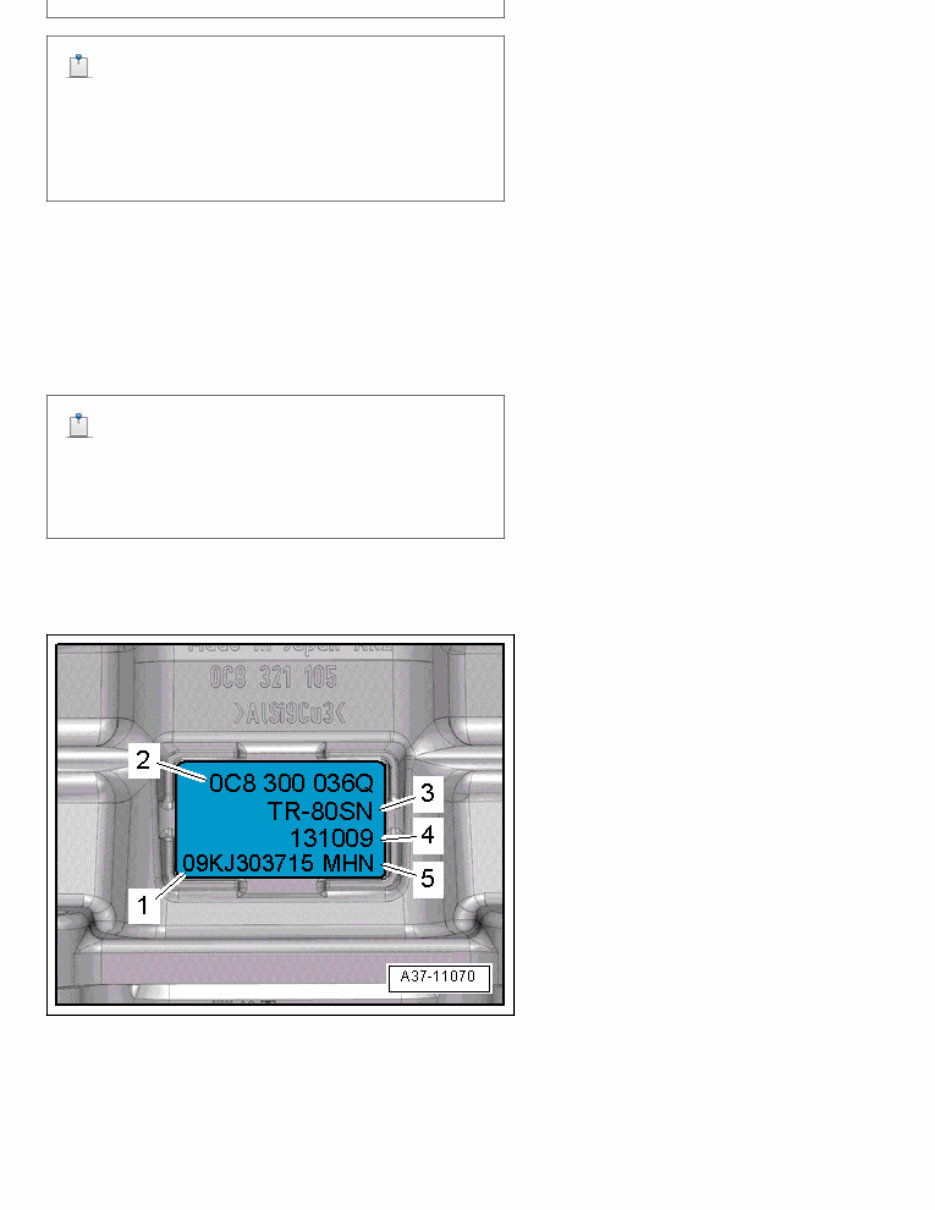
NOTE: "Tow-starting" the engine, for example when the battery is too low or the starter is not working, is not possible. 00 GENERAL, TECHNICAL DATA > GENERAL INFORMATION > TRANSMISSION IDENTIFICATION > The "8-speed automatic transmission 0C8, AWD" is installed in the Audi Q7 from MY 07. For the correct allocation, refer to CODE LETTERS, TRANSMISSION ALLOCATIONS, RATIOS AND EQUIPMENT . Transmission code letters are located on the type plate on the left side of the transmission at the bottom. NOTE: The transmission code letters are also included on the vehicle data labels. Example: 1. Manufacturer serial number 2. Part number 3. Manufacturer type number Fig 1: Identifying Transmission Identification Courtesy of AUDI OF AMERICA, LLC
4. Production date 5. Transmission code 00 GENERAL, TECHNICAL DATA > DESCRIPTION AND OPERATION > TRANSMISSION ADAPTATION > In addition to the construction, the deciding factor for good and constant shift quality is the precise control of the shifting elements. To maintain a consistent shift quality throughout the entire transmission service live, various control and regulation parameters must be adapted continuously and the determined adaptation values must be stored. These adaptations or this programming process are called adaptation. The goal of a transmission adaptation is to compensate for production tolerances of the transmission components and their changes throughout the service life. The adaptation values act as corrective values or offsets which are added to or subtracted from the values (applied values) stored permanently in the transmission control module. When should the adaptation values be read, evaluated or erased and when should an adaptation drive be performed? If the customer indicates there is rough or hard shifting behavior. After replacing the ATF. After repairing the clutches. After replacing the valve body After replacing the transmission Control Module (TCM) -J217- After replacing the transmission After a software update. After certain engine repairs such as replacing the Mass Airflow (MAF) sensor. -- Follow the instructions, procedures and requirements in "Guided Functions" exactly. The vehicle diagnostic tester is connected, then select and perform 02 - transmission electronics 0C8 I J217 and then J217 - transmission control module, Adaptation drive (Repair Group 38) using Guided Functions . NOTE: After erasing the adaptation values, perform an adaptation drive using "Guided Functions or Fault Finding". If the adaptation drive cannot be performed for various reason, complete an extensive test drive. Be sure to keep to the adaptation conditions as much as possible. General Adaptation Conditions The adaptation can only take place when the appropriate defined adaptation conditions are met. The following information provides an overview of the criteria that must be met during an adaptation: The ATF must be within a certain temperature range.
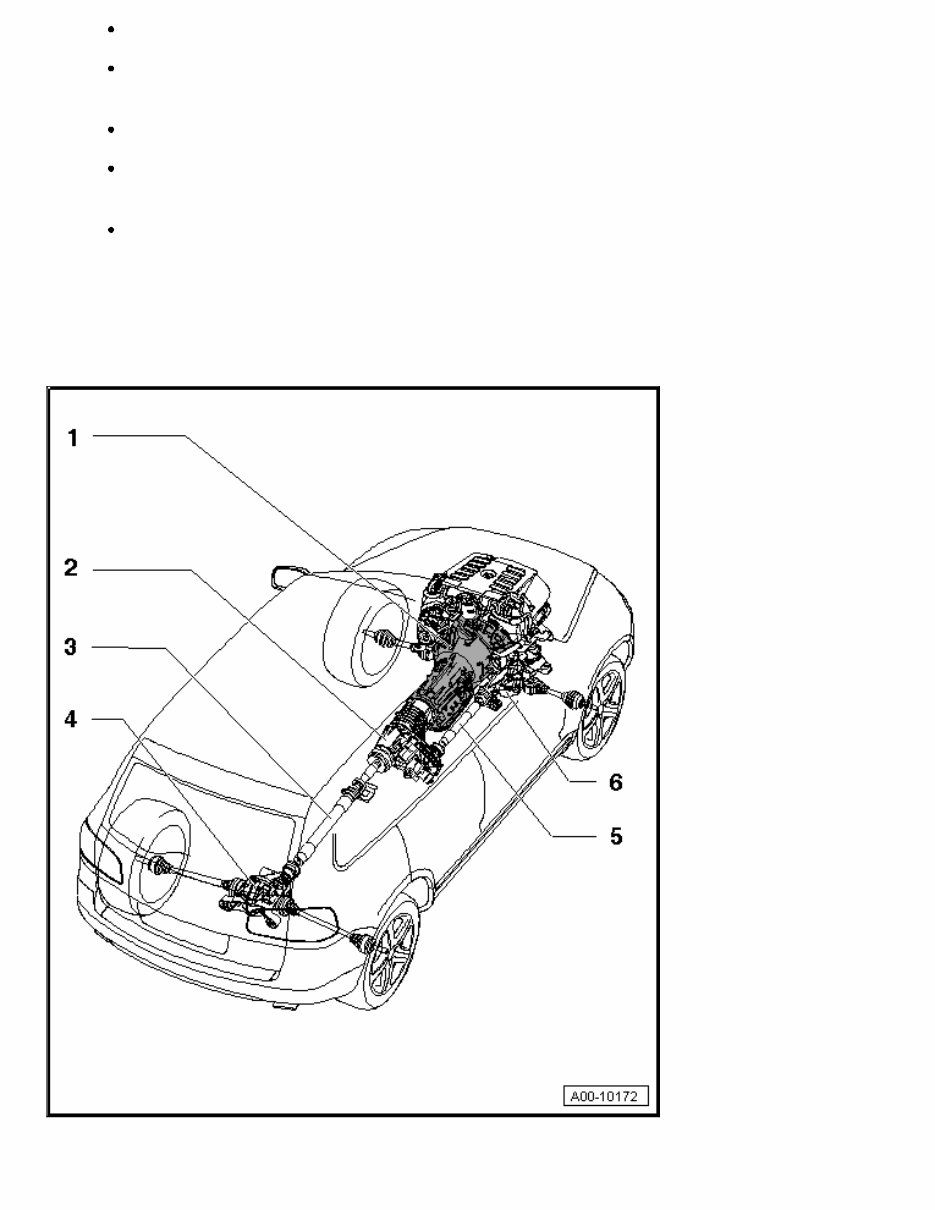
A certain gear or selector lever position must be engaged. The engine load must be within a certain range. Generally a very low engine load or very light pressure on the accelerator pedal is required. There must be no Diagnostic Trouble Code (DTC) entries in the transmission control module. Certain vehicle conditions must be present such as acceleration or deceleration, constant driving, vehicle stopped with the engine running at idle, etc. There must be good road conditions, optimum road surface, no steep inclines or declines and the road must be as level as possible. 00 GENERAL, TECHNICAL DATA > DESCRIPTION AND OPERATION > TRANSMISSION OVERVIEW > Fig 1: Transmission Overview Courtesy of AUDI OF AMERICA, LLC
1. 8-Speed Automatic Transmission 0C8 1. 3.0L TFSI, refer to TRANSMISSION, REMOVING or 3.0L TDI, refer to TRANSMISSION, REMOVING 2. Transfer Case 1. Removing and installing, refer to FRONT FINAL DRIVE 3. Rear Driveshaft 1. Removing and installing, refer to REAR FINAL DRIVE 4. Rear Final Drive 1. Removing and installing, refer to REAR FINAL DRIVE 5. Front Driveshaft 1. Removing and installing, refer to FRONT FINAL DRIVE 6. Front Final Drive 1. Removing and installing, refer to FRONT FINAL DRIVE 00 GENERAL, TECHNICAL DATA > SPECIFICATIONS > CAPACITIES > 8-Speed Automatic Transmission 0C8 Capacities Transmission initial filling for engine type: V6 3.0L - TFSI Refer to the Fluid Capacity Tables Transmission initial filling for engine type: V6 3.0L - TDI Refer to the Fluid Capacity Tables ATF cooling system Refer to the Fluid Capacity Tables ATF change No ATF change Permanent fill Changing only after repair, for example, when removing the ATF pan, approximately 6 liters Lubricant ATF CAUTION: Using the incorrect ATF will result in malfunctions or transmission failure. Only ATF available as a replacement part for the 8-speed automatic transmission 0C8 may be used in the planetary gear. -- ATF LEVEL INSIDE TRANSMISSION .
00 GENERAL, TECHNICAL DATA > SPECIFICATIONS > CODE LETTERS, TRANSMISSION ALLOCATIONS, RATIOS AND EQUIPMENT > 8-Speed Automatic Transmission 0C8 Transmission Code letters MHC NAB NAC MHN Allocation Type Audi Q7 from MY 07 Audi Q7 from MY 07 Engine 3.0L - TDI 150 kW, 165 kW, 176 kW and 180 kW 3.0L - TFSI 200 kW and 245 kW 1st Gear 4.970 4.845 2nd Gear 2.840 2.840 3rd Gear 1.864 1.864 4th Gear 1.437 1.437 5th Gear 1.210 1.217 6th Gear 1.000 1.000 7th Gear 0.825 0.816 8th Gear 0.686 0.672 Reverse gear 4.066 3.825
This repair manual is a valuable resource for both professional mechanics and DIY enthusiasts. It contains comprehensive troubleshooting and replacement procedures recommended by the manufacturer, accompanied by step-by-step instructions, clear images, and exploded-view illustrations.
Regular maintenance is essential for the durability of your vehicle. Over time, certain parts will wear out and require replacement. This manual provides the manufacturer's recommended troubleshooting charts and replacement procedures, enabling you to save on repairs, enhance your vehicle's reliability, and minimize visits to the repair shop.
Featuring step-by-step instructions, exploded-view illustrations, and clear images, this manual eliminates the need to search through numerous pages for specific information. It offers a convenient digital format, allowing easy access, search, screenshot, and bookmark functions, making it more practical than a traditional bound manual.
For those who prefer a physical copy, the manual is also printable. It is available in .pdf format and compatible with various electronic devices, including PC, Mac computers, Android and Apple smartphones, and tablets. Adobe Reader (free) is the only requirement for accessing the manual.