Protected by copyright. Copying for private or commercial purposes, in part or in whole, is not permitted unless authorised by AUDI AG. AUDI AG does not guarantee or accept any liability with respect to the correctness of information in this document. Copyright by AUDI AG. 4.2l petrol engine , CDRA From January 2010 Audi A8 Current Flow Diagram No. 1 / 1 11.2013
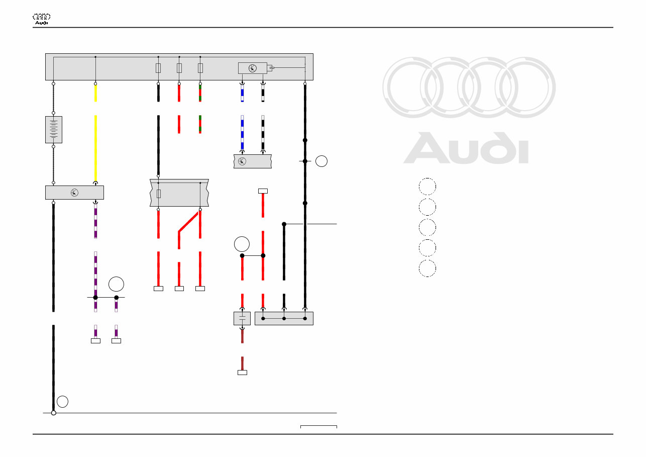
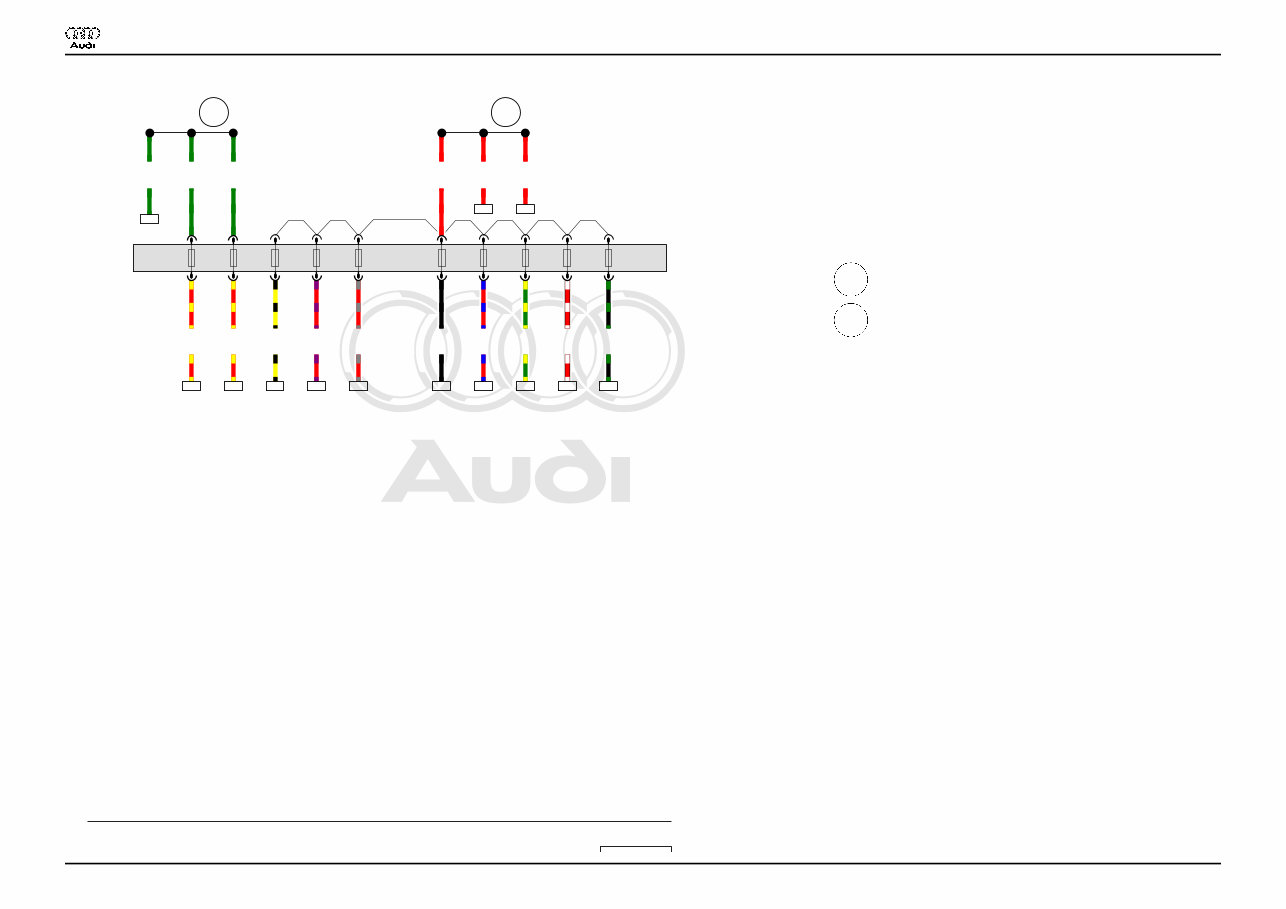
Protected by copyright. Copying for private or commercial purposes, in part or in whole, is not permitted unless authorised by AUDI AG. AUDI AG does not guarantee or accept any liability with respect to the correctness of information in this document. Copyright by AUDI AG. 1 2 3 4 5 6 7 8 9 10 11 12 13 14 4H0-001021113 D50 C24 TV22 N253 A J367 624 B481 S132 J234 J505 * J492 P2 519 U6 SD1 SD2 SD3 6.0 rt 284 10.0 rt 2.5 rt 2 2.5 br 79 1 50.0 sw A1 - B1 A1 + 0.5 ge B1 T2s /2 0.35 vi/ws T2s /1 0.35 vi/ws 380 25.0 sw C1 A1 0.5 bl/ws T2b /1 T100 /74 0.5 sw/ws T2b /2 T100 /75 10.0 rt D1 4.0 rt/gn E1 0.35 vi/ws 27 6.0 rt 32 D4 4.0 rt 29 D4 50.0 sw 16.0 rt 60 C3A *2 F1 *2 *2 *2 284 79 380 27 32 29 60 ws = white sw = black ro = red rt = red br = brown gn = green bl = blue gr = grey li = purple vi = purple ge = yellow or = orange rs = pink Battery, Suppression filter, Battery monitor control unit, Battery isolation igniter, Fuse 2 A Battery C24 Suppression filter J234 Airbag control unit J367 Battery monitor control unit J492 All-wheel drive control unit J505 Heated windscreen control unit N253 Battery isolation igniter, near battery SD1 Fuse 1 on fuse holder D SD2 Fuse 2 on fuse holder D SD3 Fuse 3 on fuse holder D S132 Fuse 2, on right in luggage compartment T2b 2-pin connector T2s 2-pin connector TV22 Terminal 30 wiring junction 2 T100 100-pin connector U6 Jump start socket 519 Threaded connection (30), on flat conductor 624 Earth point, starter battery B481 Connection 17, in main wiring harness D50 Positive connection (30), in engine compartment wiring harness P2 Positive connection (30), in battery wiring harness * see applicable current flow diagram for basic equipment *2 Flat conductor Audi A8 Current Flow Diagram No. 1 / 2 11.2013
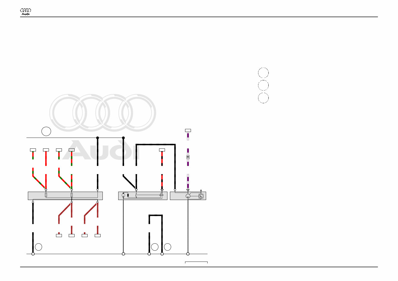
Protected by copyright. Copying for private or commercial purposes, in part or in whole, is not permitted unless authorised by AUDI AG. AUDI AG does not guarantee or accept any liability with respect to the correctness of information in this document. Copyright by AUDI AG. 15 16 17 18 19 20 21 22 23 24 25 26 27 28 4H0-001031113 C G S42 B M P2 P2 685 C1 S104 685 727 2.5 rt/sw 34 T1c /1 50 0.35 vi/ws T17f /14 T2 /1 D+ 0.35 vi/ws 4 T17f /14 50.0 sw 30 16.0 sw C1 6.0 rt/gn 341 * 1A 10.0 rt 340 *2 1A 6.0 br 343 * D1 10.0 br 342 *2 D1 6.0 rt/gn 348 * 2A 10.0 rt/gn 347 *2 2A 6.0 br 350 * E1 10.0 br 349 *2 E1 16.0 sw F1 25.0 sw 30 B+ 50.0 sw DF 34 4 341 340 343 342 348 347 350 349 ws = white sw = black ro = red rt = red br = brown gn = green bl = blue gr = grey li = purple vi = purple ge = yellow or = orange rs = pink Starter, Alternator B Starter C Alternator C1 Voltage regulator S42 Radiator fan single fuse, front right in engine compartment S104 Radiator fan fuse for 2nd speed T1c Single connector T2 2-pin connector T17f 17-pin connector, in E-box in engine compartment 685 Earth point 1 at front of right longitudinal member 727 Earth point, on oil reservoir P2 Positive connection (30), in battery wiring harness * Only models with no trailer socket *2 Only models with trailer socket Audi A8 Current Flow Diagram No. 1 / 3 11.2013
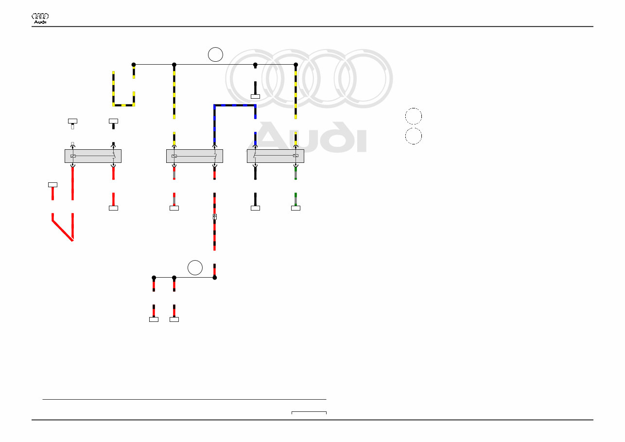
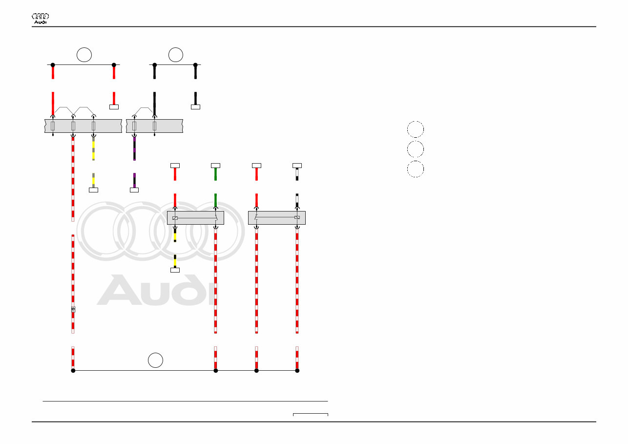
Protected by copyright. Copying for private or commercial purposes, in part or in whole, is not permitted unless authorised by AUDI AG. AUDI AG does not guarantee or accept any liability with respect to the correctness of information in this document. Copyright by AUDI AG. 29 30 31 32 33 34 35 36 37 38 39 40 41 42 4H0-001041113 D97 J329 J695 J53 B277 S41 * SF15 ST1 *2 0.5 rt/sw 72 2.5 rt/sw T17g /17 2.5 rt/sw 25 0.5 sw/ws 86 2 6.0 sw 64 5 1.5 sw/ge 1B 2.5 sw/bl 5B 3A 1.5 sw/ge 1A 2.5 rt/sw 5A T17g /17 0.35 gr/rt 81 2A 0.35 gr/gn 80 2B 2.5 sw 2.5 sw 39 39 3B 6.0 rt 7 3 1.5 rt 1 4.0 rt 8 4.0 sw/ge 15a 72 25 86 64 81 80 39 39 7 8 ws = white sw = black ro = red rt = red br = brown gn = green bl = blue gr = grey li = purple vi = purple ge = yellow or = orange rs = pink Starter motor relay, Terminal 15 voltage supply relay, Starter motor relay 2 J53 Starter motor relay J329 Terminal 15 voltage supply relay J695 Starter motor relay 2 ST1 Fuse carrier 1 SF15 Fuse 15 in fuse holder F S41 Heated rear window single fuse T17g 17-pin connector, in E-box in engine compartment B277 Positive connection 1 (15a) in main wiring harness D97 Connection (50), in engine compartment right wiring harness * see applicable current flow diagram for basic equipment *2 see applicable current flow diagram for fuse assignment Audi A8 Current Flow Diagram No. 1 / 4 11.2013
Protected by copyright. Copying for private or commercial purposes, in part or in whole, is not permitted unless authorised by AUDI AG. AUDI AG does not guarantee or accept any liability with respect to the correctness of information in this document. Copyright by AUDI AG. 43 44 45 46 47 48 49 50 51 52 53 54 55 56 4H0-001051113 SA D113 D101 SA3 SA4 SA5 SA6 SA7 SA8 SA9 SA10 SA11 SA12 1.0 gn/ge 296 10a 1.0 rt/bl 71 9a 1.0 sw/gn 309 12a 0.35 sw 352 8a 1.0 rt/ws 237 11a 4.0 gn 65 4.0 gn 4 4.0 gn 3 2.5 rt/ge 111 3a 1.0 rt 63 4.0 rt 67 6.0 rt 8 1.0 rt/ge 271 4a 1.0 rt/gr 280 7a 0.35 rt/vi 327 6a 0.35 ge/sw 346 5a 5 6 7 9 10 11 12 296 71 309 352 237 65 111 63 67 271 280 327 346 ws = white sw = black ro = red rt = red br = brown gn = green bl = blue gr = grey li = purple vi = purple ge = yellow or = orange rs = pink Fuse holder A SA Fuse holder A SA3 Fuse 3 in fuse holder A SA4 Fuse 4 in fuse holder A SA5 Fuse 5 in fuse holder A SA6 Fuse 6 in fuse holder A SA7 Fuse 7 in fuse holder A SA8 Fuse 8 in fuse holder A SA9 Fuse 9 in fuse holder A SA10 Fuse 10 in fuse holder A SA11 Fuse 11 in fuse holder A SA12 Fuse 12 in fuse holder A D101 Connection 1 in engine compartment wiring harness D113 Connection 11 in engine compartment wiring harness Audi A8 Current Flow Diagram No. 1 / 5 11.2013
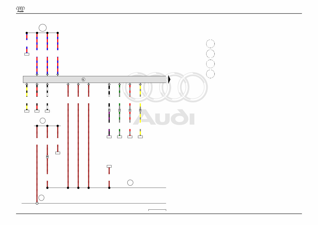
Protected by copyright. Copying for private or commercial purposes, in part or in whole, is not permitted unless authorised by AUDI AG. AUDI AG does not guarantee or accept any liability with respect to the correctness of information in this document. Copyright by AUDI AG. 57 58 59 60 61 62 63 64 65 66 67 68 69 70 4H0-001061113 E89 J757 J271 B273 B272 ST2 ST1 SB3 SB6 SF6 SF14 SB4 0.5 ws/sw 73 1 0.5 ge/sw 71 1 4.0 gn 44 5 4.0 rt/ws 3 4.0 rt/ws 3 1.0 rt/ws 2 1.0 rt 52 2 4.0 rt 53 5 6.0 sw 32 6.0 rt 3 16.0 rt 6 6.0 sw 6 0.35 sw/vi 79 14a 4.0 rt/ws T17f /16 4a 4.0 rt/ws T17f /16 0.35 ge/gr 82 6a 14 6a 4 6 3a 73 71 44 52 53 32 6 79 82 ws = white sw = black ro = red rt = red br = brown gn = green bl = blue gr = grey li = purple vi = purple ge = yellow or = orange rs = pink Main relay, Engine component current supply relay J271 Main relay J757 Engine component current supply relay ST1 Fuse carrier 1 ST2 Fuse carrier 2 SB3 Fuse 3 on fuse holder B SB4 Fuse 4 on fuse holder B SF6 Fuse 6 in fuse holder F SB6 Fuse 6 on fuse holder B SF14 Fuse 14 in fuse holder F T17f 17-pin connector, in E-box in engine compartment B272 Positive connection (30), in main wiring harness B273 Positive connection (15), in main wiring harness E89 Positive connection (30a) in engine wiring harness Audi A8 Current Flow Diagram No. 1 / 6 11.2013
Protected by copyright. Copying for private or commercial purposes, in part or in whole, is not permitted unless authorised by AUDI AG. AUDI AG does not guarantee or accept any liability with respect to the correctness of information in this document. Copyright by AUDI AG. 71 72 73 74 75 76 77 78 79 80 81 82 83 84 4H0-001071113 J623 85 85 D103 380 43 2.5 br T91 /1 31 2.5 br T91 /4 31 2.5 br T91 /2 31 1.0 rt/bl T91 /6 1.0 rt/bl T91 /3 1.0 rt/bl T91 /5 0.5 rt/sw 35 T91 /51 50 0.5 ws/sw 69 T91 /87 0.5 ge/sw 63 T91 /35 1.0 rt/bl 52 2.5 br 10 4.0 br 284 6.0 br 0.35 gr/gn T91 /52 T17f /10 0.35 gr/rt T91 /70 T17f /9 0.35 gr/rt 35 T17f /9 0.35 gr/gn 41 T17f /10 4.0 br T17g /16 4.0 br T17g /16 0.35 sw/vi 61 T17g /7 0.35 sw/ws T17g /7 T91 /50 0.35 ge/gr T17g /6 T91 /86 0.35 ge/gr 59 T17g /6 35 69 63 52 10 284 35 41 61 59 ws = white sw = black ro = red rt = red br = brown gn = green bl = blue gr = grey li = purple vi = purple ge = yellow or = orange rs = pink Engine control unit J623 Engine control unit T17f 17-pin connector, in E-box in engine compartment T17g 17-pin connector, in E-box in engine compartment T91 91-pin connector 43 Earth point, lower part of right A-pillar 85 Earth connection 1, in engine compartment wiring harness 380 Earth connection 15, in main wiring harness D103 Connection 3 in engine compartment wiring harness Audi A8 Current Flow Diagram No. 1 / 7 11.2013
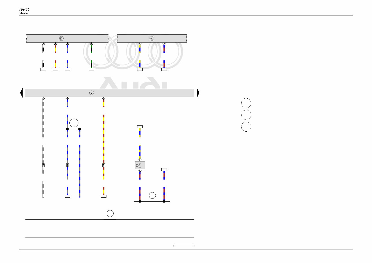
Protected by copyright. Copying for private or commercial purposes, in part or in whole, is not permitted unless authorised by AUDI AG. AUDI AG does not guarantee or accept any liability with respect to the correctness of information in this document. Copyright by AUDI AG. 85 86 87 88 89 90 91 92 93 94 95 96 97 98 4H0-001081113 J623 85 85 E26 J527 E45 * J393 J217 85 J519 G32 410 0.35 gr/bl T91 /17 P-N 0.35 gr/ws T91 /34 T14b /5 0.35 gr/ws T14b /5 T16d /5 0.35 gr/bl T17f /12 0.35 gr/bl 0.35 gr/bl 88 88 T17f /12 T32c /28 0.35 gr/bl T16a /1 0.35 ge/br T91 /48 T17f /8 0.35 ge/br 0.35 ge/br 87 91 T17f /8 T32c /5 0.35 sw/gn 323 T32c /2 0.5 sw/ws 30 T32c /16 0.35 bl/ge 0.35 bl/ge 94 94 T32b /27 T2dh /2 0.35 br/bl T2dh /1 0.35 br/bl 0.35 br/bl 96 96 T32b /5 88 88 87 91 323 30 94 94 96 96 ws = white sw = black ro = red rt = red br = brown gn = green bl = blue gr = grey li = purple vi = purple ge = yellow or = orange rs = pink Coolant shortage indicator sender, Onboard supply control unit, Engine control unit E45 Cruise control system switch G32 Coolant shortage indicator sender J217 Automatic gearbox control unit J393 Convenience system central control unit J519 Onboard supply control unit J527 Steering column electronics control unit J623 Engine control unit T2dh 2-pin connector T14b 14-pin connector, on left in engine compartment T16a 16-pin connector T16d 16-pin connector T17f 17-pin connector, in E-box in engine compartment T32b 32-pin connector T32c 32-pin connector T91 91-pin connector 85 Earth connection 1, in engine compartment wiring harness 410 Earth connection 1 (sender earth) in main wiring harness E26 Connection (selector position P/N), in Motronic wiring harness * Only models with cruise control system (CCS) Audi A8 Current Flow Diagram No. 1 / 8 11.2013
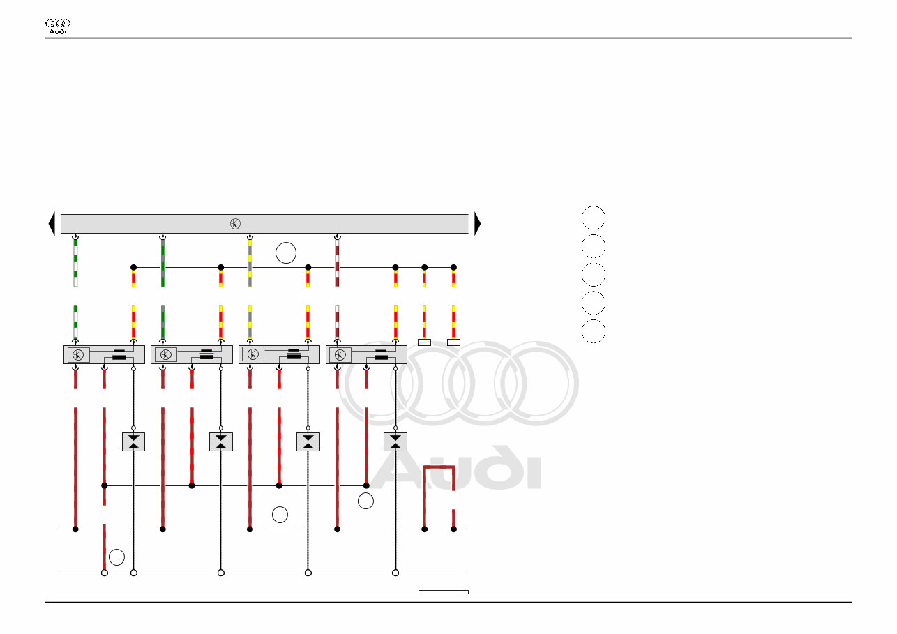
Protected by copyright. Copying for private or commercial purposes, in part or in whole, is not permitted unless authorised by AUDI AG. AUDI AG does not guarantee or accept any liability with respect to the correctness of information in this document. Copyright by AUDI AG. 99 100 101 102 103 104 105 106 107 108 109 110 111 112 4H0-001091113 J623 85 131 132 D102 N70 N127 N291 N292 600 Q P Q Q Q P P P 85 0.5 gn/gr T105 /71 T4r /3 0.5 br/ws T105 /94 T4t /3 0.5 gr/ge T105 /70 T4s /3 0.5 ws/gn T105 /93 T4q /3 2.5 br T4t /2 2.5 br T4s /2 2.5 br T4r /2 2.5 br T4q /2 2.5 br/rt T4t /4 2.5 br/rt T4s /4 2.5 br/rt T4r /4 2.5 br/rt T4q /4 2.5 rt/ge T4s /1 2.5 rt/ge T4r /1 2.5 rt/ge T4q /1 2.5 rt/ge T4t /1 2.5 rt/ge 126 2.5 rt/ge 45 4.0 br 2.5 br/rt I II III IV 126 45 ws = white sw = black ro = red rt = red br = brown gn = green bl = blue gr = grey li = purple vi = purple ge = yellow or = orange rs = pink Engine control unit, Ignition coil 1 with output stage, Spark plug connector, Spark plugs J623 Engine control unit N70 Ignition coil 1 with output stage N127 Ignition coil 2 with output stage N291 Ignition coil 3 with output stage N292 Ignition coil 4 with output stage P Spark plug connector Q Spark plugs T4q 4-pin connector T4r 4-pin connector T4s 4-pin connector T4t 4-pin connector T105 105-pin connector 85 Earth connection 1, in engine compartment wiring harness 131 Earth connection 2, in engine compartment wiring harness 132 Earth connection 3, in engine compartment wiring harness 600 Earth point, on right cylinder head D102 Connection 2 in engine compartment wiring harness Audi A8 Current Flow Diagram No. 1 / 9 11.2013
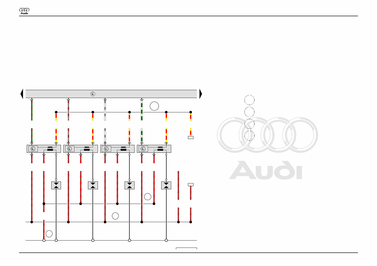
Protected by copyright. Copying for private or commercial purposes, in part or in whole, is not permitted unless authorised by AUDI AG. AUDI AG does not guarantee or accept any liability with respect to the correctness of information in this document. Copyright by AUDI AG. 113 114 115 116 117 118 119 120 121 122 123 124 125 126 4H0-001101113 J623 131 131 201 D104 N323 N324 N325 N326 601 Q Q Q Q P P P P J217 0.5 ws/gr T105 /92 T4al /3 0.5 gr/br T105 /91 T4v /3 0.5 gn/ws T105 /73 T4am /3 0.5 gn/br T105 /72 T4u /3 2.5 br/rt T4al /4 2.5 br/rt T4v /4 2.5 br/rt T4am /4 2.5 br/rt T4u /4 2.5 br/rt 2.5 rt/ge T4al /1 2.5 rt/ge T4v /1 2.5 rt/ge T4u /1 2.5 rt/ge T4am /1 2.5 rt/ge 112 2.5 br T4u /2 2.5 br T4v /2 2.5 br T4al /2 2.5 br T4am /2 1.0 br 354 V VI VII VIII 1.5 br T16a /14 112 354 ws = white sw = black ro = red rt = red br = brown gn = green bl = blue gr = grey li = purple vi = purple ge = yellow or = orange rs = pink Engine control unit, Ignition coil 5 with output stage, Spark plug connector, Spark plugs J217 Automatic gearbox control unit J623 Engine control unit N323 Ignition coil 5 with output stage N324 Ignition coil 6 with output stage N325 Ignition coil 7 with output stage N326 Ignition coil 8 with output stage P Spark plug connector Q Spark plugs T4al 4-pin connector T4am 4-pin connector T4u 4-pin connector T4v 4-pin connector T16a 16-pin connector T105 105-pin connector 131 Earth connection 2, in engine compartment wiring harness 201 Earth connection 5, in engine compartment wiring harness 601 Earth point, on left cylinder head D104 Positive connection 2 (30a), in engine compartment wiring harness Audi A8 Current Flow Diagram No. 1 / 10 11.2013
Get your hands on the 2011 Audi A8 (D4) Service & Repair Manual to tackle vehicle issues like a pro. Whether you're a professional mechanic or a DIY enthusiast, these Auto Repair Manuals provide comprehensive instructions and procedures to help you fix your ride with ease. The manual contains technical data, diagrams, a complete list of car parts, and images, making it suitable for both novice and experienced car mechanics. It covers all models and repairs A-Z, offering step-by-step instructions, wiring schematics, and specifications for a hassle-free repair experience.
These manuals are not generic; they are vehicle-specific and used by technicians at dealerships to maintain, service, diagnose, and repair vehicles. The factory highly detailed repair manuals include instructions, illustrations, wiring schematics, and diagrams to fully service and repair your vehicle. They are compatible with Windows Vista, XP, ME, 98, NT, 2000, and Mac, ensuring accessibility for all users. The manual covers various aspects including maintenance, engine, control system, mechanical, fuel service specifications, and much more.
With printable pages, you can easily take the manual with you to your vehicle or workshop. The comprehensive information provided can save you time and money, allowing you to stay updated and knowledgeable about your car. Say goodbye to relying solely on your mechanic and embrace the fun and empowerment of DIY car repair. The manual is easily accessible on your PC and can be printed in a matter of seconds, ensuring durability and convenience.
Compatible with all versions of Windows and Mac, these Auto Repair Manuals are a valuable resource for anyone looking to enhance their car repair knowledge and skills. Say hello to hassle-free car repairs and bid farewell to flipping through numerous books to find what you need. Embrace the convenience and empowerment of DIY car repair with these comprehensive and user-friendly repair manuals.