Protected by copyright. Copying for private or commercial purposes, in part or in whole, is not permitted unless authorised by AUDI AG. AUDI AG does not guarantee or accept any liability with respect to the correctness of information in this document. Copyright by AUDI AG. Workshop Manual Audi A6 2005 ➤ 4-cylinder direct petrol injection engine (2.0 ltr. 4-valve turbo), mechanics Engine ID BPJ BYK Edition 03.2012 Service Service Department. Technical Information
Protected by copyright. Copying for private or commercial purposes, in part or in whole, is not permitted unless authorised by AUDI AG. AUDI AG does not guarantee or accept any liability with respect to the correctness of information in this document. Copyright by AUDI AG. 1.5 Stress-free alignment of exhaust system . . . . . . . . . . . . . . . . . . . . . . . . . . . . . . . . . . . . . . 188 1.6 Checking exhaust system for leaks . . . . . . . . . . . . . . . . . . . . . . . . . . . . . . . . . . . . . . . . . . 190 Audi A6 2005 ➤ 4-cylinder direct petrol injection engine (2.0 ltr. 4-valve turbo), mechanics - Edition 03.2012 Contents iii
Protected by copyright. Copying for private or commercial purposes, in part or in whole, is not permitted unless authorised by AUDI AG. AUDI AG does not guarantee or accept any liability with respect to the correctness of information in this document. Copyright by AUDI AG. Audi A6 2005 ➤ 4-cylinder direct petrol injection engine (2.0 ltr. 4-valve turbo), mechanics - Edition 03.2012 iv Contents
Protected by copyright. Copying for private or commercial purposes, in part or in whole, is not permitted unless authorised by AUDI AG. AUDI AG does not guarantee or accept any liability with respect to the correctness of information in this document. Copyright by AUDI AG. 00 – Technical data 1 Technical data The engine number („Engine code“ and „Serial number“) can be found at the front of the joint between engine and gearbox. Additionally there is a sticker on the toothed belt cover showing the „engine code“ and „serial number“. The engine code is also indicated on the vehicle data stickers. Audi A6 2005 ➤ 4-cylinder direct petrol injection engine (2.0 ltr. 4-valve turbo), mechanics - Edition 03.2012 1. Technical data 1
Protected by copyright. Copying for private or commercial purposes, in part or in whole, is not permitted unless authorised by AUDI AG. AUDI AG does not guarantee or accept any liability with respect to the correctness of information in this document. Copyright by AUDI AG. 2 Engine data Code letters BPJ BYK Capacity ltr. 1.984 1.984 Power output kW at rpm 125/4200 125/4200 Torque Nm at rpm 280/1800 280/1800 Bore ∅ mm 82.5 82.5 Stroke mm 92.8 92.8 Compression ratio 10.5 10.5 RON 98 1) 98 1) Injection/ignition system FSI FSI Firing order 1-3-4-2 1-3-4-2 Knock control yes yes Turbocharging/super‐ charging yes yes Exhaust gas recirculation no no Intake manifold change- over no no Variable valve timing yes yes Secondary air system no no • 1) Unleaded petrol RON 95 can also be used, but results in reduced power Audi A6 2005 ➤ 4-cylinder direct petrol injection engine (2.0 ltr. 4-valve turbo), mechanics - Edition 03.2012 2 Rep. gr.00 - Technical data
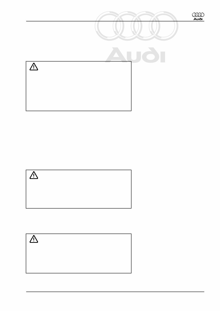
Protected by copyright. Copying for private or commercial purposes, in part or in whole, is not permitted unless authorised by AUDI AG. AUDI AG does not guarantee or accept any liability with respect to the correctness of information in this document. Copyright by AUDI AG. 3 Safety precautions 3.1 Working on the fuel system When working on the fuel system note the following warnings: WARNING The fuel system operates at extremely high pressure. This can cause injury. ♦ The fuel pressure in the high-pressure section of the in‐ jection system must be reduced to a residual pressure prior to opening the system. ♦ Wrap a clean cloth around the connection and carefully loosen the connection to allow the residual pressure to dissipate. – Procedure before opening high-pressure section of injection system ⇒ Rep. gr. 24 . Observe the following to prevent injuries to persons and damage to the injection and ignition system: ♦ Always switch off the ignition before connecting or discon‐ necting electrical wiring for the injection or ignition system or tester cables. ♦ Always switch off ignition before washing engine. ♦ Faults are stored in engine control units if electrical connectors were unplugged and engine was started: „Generate readiness code“ in „Guided Functions“ ⇒ Vehicle diagnostic tester . Caution To prevent irreparable damage to the electronic components when disconnecting the battery: ♦ Observe notes on procedure for disconnecting the battery. ♦ Always switch off the ignition before disconnecting the battery. – Disconnect battery ⇒ Rep. gr. 27 . 3.2 Procedure before opening high-pres‐ sure section of injection system WARNING ♦ The injection system consists of a high-pressure section (maximum approx. 120 bar) and a low-pressure section (approx. 6 bar). ♦ The fuel pressure in the high-pressure section must be reduced to a residual pressure of approx. 6 bar prior to opening the system. Procedure ⇒ Rep. gr. 24 . Audi A6 2005 ➤ 4-cylinder direct petrol injection engine (2.0 ltr. 4-valve turbo), mechanics - Edition 03.2012 3. Safety precautions 3
Protected by copyright. Copying for private or commercial purposes, in part or in whole, is not permitted unless authorised by AUDI AG. AUDI AG does not guarantee or accept any liability with respect to the correctness of information in this document. Copyright by AUDI AG. 3.3 Working on the cooling system When working on the cooling system note the following warnings: WARNING Hot steam/hot coolant can escape - risk of scalding. ♦ The cooling system is under pressure when the engine is hot. ♦ To allow pressure to dissipate, cover filler cap on coolant expansion tank with cloth and open carefully. Caution Overheating can occur if the filler cap is not fitted properly. ♦ The filler cap must engage positively and audibly when it is closed. 3.4 Using testers and measuring instru‐ ments during a road test Note the following if testers and measuring instruments have to be used during a road test: WARNING Accidents can be caused if the driver is distracted by test equipment while road-testing, or if test equipment is not prop‐ erly secured. Persons sitting in the front passenger's seat could be injured if the airbag is triggered in an accident. • The use of test equipment while driving causes distraction. • There is an increased risk of injury if test equipment is not secured. ♦ Test equipment must always be secured on the rear seat with a strap and operated from the rear seat by a second person. 3.5 Working on the exhaust system When working on the exhaust system please note the following: Caution Avoid damage to flexible joint. ♦ Do not bend flexible joint more than 10°. ♦ Install flexible joint so that it is not under tension. ♦ Take care not to damage wire mesh on flexible joint. Audi A6 2005 ➤ 4-cylinder direct petrol injection engine (2.0 ltr. 4-valve turbo), mechanics - Edition 03.2012 4 Rep. gr.00 - Technical data
You're Reading a Preview
What's Included?
Lifetime Access
Fast Download Speeds
Online & Offline Access
Access PDF Contents & Bookmarks
Full Search Facility
Print one or all pages of your manual
$35.99
2008-2010 Audi A6 (C6) OEM Service & Repair Manual
2008-2010 Audi A6 (C6) OEM Service & Repair Manual
Engines covered:
2.0L I4
2.4L V6
2.8L V6 FSI
3.0L V6 supercharged
3.2L V6 FSI
4.2L V8
5.0L V10
5.2L V10
2.0L I4 TDI (diesel)
2.7L V6 TDI (diesel)
3.0L V6 TDI (diesel)
The 2008-2010 Audi A6 (C6) OEM Service & Repair Manual is the go-to resource for anyone working on this generation of Audi—whether you're dealing with the 2.0L TDI or diving into a V10-powered S6. It’s packed with factory procedures, technical data, and specs that cover everything from oil changes to drivetrain tear-downs.
You'll find clear step-by-step instructions for all major engine variants—gas and diesel alike—including timing setups, turbo components, and emissions systems. Transmission sections cover manual, automatic, Multitronic, and Quattro-specific procedures, so no matter the drivetrain, you're sorted. It even details common service intervals and component replacement techniques that save time in the bay or garage.
Content overview:
Covers all 4-cylinder, 6-cylinder, 8-cylinder, and 10-cylinder petrol and TDI diesel engines
Includes service procedures for direct injection, unit injector, and supercharged engines
Detailed repair instructions for 6-speed manual and automatic gearboxes (0A2, 0A3, 01X, 02X)
Coverage for automatic gearboxes (09E, 09L), multitronic (01J, 0AN), and quattro systems
Includes Simos direct injection and TDI injection systems with glow plug diagnostics
Step-by-step maintenance and service data for engine control, ignition, fuel, and emissions
Front-wheel drive and four-wheel drive final drives, drivetrains, and axles covered
Comprehensive repair info on brakes, steering, suspension, and wheels
Includes body repairs, lighting systems, HVAC, and general electrical components
Complete wiring diagrams and electrical troubleshooting procedures
Includes Audi RS6 and S6-specific engine data and service sections
This manual’s solid for professional techs chasing stubborn codes, and just as helpful for DIYers doing their first suspension swap or fluid change. Straightforward, thorough, and made for wrench-turners who want the right info the first time.
Printable: Yes Language: English Compatibility: Pretty much any electronic device, incl. PC & Mac computers, Android and Apple smartphones & tablet, etc. Requirements: Adobe Reader (free)
Reviews
Q&A
Recently Viewed
5,521,897Happy Clients
2,594,462eManuals
1,120,453Trusted Sellers
15Years in Business
Price:
Actual Price:
2008-2010 Audi A6 (C6) OEM Service & Repair Manual