Protected by copyright. Copying for private or commercial purposes, in part or in whole, is not
permitted unless authorised by AUDI AG. AUDI AG does not guarantee or accept any liability
with respect to the correctness of information in this document. Copyright by AUDI AG.
Repair Manual
Audi A6 2011 ➤
Audi A6 China 2012 ➤
Audi A7 Sportback 2011 ➤
4-Cylinder Direct Injection 1.8L; 2.0L Turbo 4V TFSI
Engine (Generation II)
Engine ID
CAE
B
CHJA
CAE
D
Edition 10.2016
Service
Service Department. Technical Information
Protected by copyright. Copying for private or commercial purposes, in part or in whole, is not
permitted unless authorised by AUDI AG. AUDI AG does not guarantee or accept any liability
with respect to the correctness of information in this document. Copyright by AUDI AG.
List of Workshop Manual Repair Groups
Repair Group
00 - General, Technical Data
10 - Engine Assembly
13 - Crankshaft, Cylinder Block
15 - Cylinder Head, Valvetrain
17 - Lubrication
19 - Cooling System
21 - Turbocharger, Supercharger
24 - Multiport Fuel Injection
26 - Exhaust System, Emission Controls
28 - Ignition/Glow Plug System
Technical information should always be available to the foremen and mechanics, because their
careful and constant adherence to the instructions is essential to ensure vehicle road-worthiness and
safety. In addition, the normal basic safety precautions for working on motor vehicles must, as a
matter of course, be observed.
Service
All rights reserved.
No reproduction without prior agreement from publisher.
Copyright © 2016 Audi AG, Ingolstadt D3E80391D2E
Protected by copyright. Copying for private or commercial purposes, in part or in whole, is not
permitted unless authorised by AUDI AG. AUDI AG does not guarantee or accept any liability
with respect to the correctness of information in this document. Copyright by AUDI AG.
Contents
00 - General, Technical Data . . . . . . . . . . . . . . . . . . . . . . . . . . . . . . . . . . . . . . . . . . . . 1
1 Identification . . . . . . . . . . . . . . . . . . . . . . . . . . . . . . . . . . . . . . . . . . . . . . . . . . . . . . . . . . . . 1
1.1 Engine Number/Engine Specifications . . . . . . . . . . . . . . . . . . . . . . . . . . . . . . . . . . . . . . . . 1
2 Safety Precautions . . . . . . . . . . . . . . . . . . . . . . . . . . . . . . . . . . . . . . . . . . . . . . . . . . . . . . . . 2
2.1 Safety Precautions when Working on High-Voltage Vehicles . . . . . . . . . . . . . . . . . . . . . . 2
2.2 Safety Precautions when Working on Fuel Supply System . . . . . . . . . . . . . . . . . . . . . . . . 9
2.3 Safety Precautions when Working on Vehicles with Start/Stop System . . . . . . . . . . . . . . 9
2.4 Safety Precautions when Working on Subframe . . . . . . . . . . . . . . . . . . . . . . . . . . . . . . . . 9
2.5 Safety Precautions during Road Test with Testing Equipment . . . . . . . . . . . . . . . . . . . . . . 10
2.6 Safety Precautions when Working on Ignition System . . . . . . . . . . . . . . . . . . . . . . . . . . . . 10
2.7 Safety Precautions when Working on Cooling System . . . . . . . . . . . . . . . . . . . . . . . . . . . . 10
3 Repair Information . . . . . . . . . . . . . . . . . . . . . . . . . . . . . . . . . . . . . . . . . . . . . . . . . . . . . . . . 11
3.1 Guidelines for Clean Working Conditions . . . . . . . . . . . . . . . . . . . . . . . . . . . . . . . . . . . . . . 11
3.2 Foreign Objects in Engine . . . . . . . . . . . . . . . . . . . . . . . . . . . . . . . . . . . . . . . . . . . . . . . . . . 11
3.3 Contact Corrosion . . . . . . . . . . . . . . . . . . . . . . . . . . . . . . . . . . . . . . . . . . . . . . . . . . . . . . . . 11
3.4 Line Routing and Securing . . . . . . . . . . . . . . . . . . . . . . . . . . . . . . . . . . . . . . . . . . . . . . . . . . 12
3.5 Radiator and Condenser Assembly . . . . . . . . . . . . . . . . . . . . . . . . . . . . . . . . . . . . . . . . . . 12
3.6 Vacuum System, Checking . . . . . . . . . . . . . . . . . . . . . . . . . . . . . . . . . . . . . . . . . . . . . . . . 12
10 - Engine Assembly . . . . . . . . . . . . . . . . . . . . . . . . . . . . . . . . . . . . . . . . . . . . . . . . . . 13
1 Engine, Removing and Installing . . . . . . . . . . . . . . . . . . . . . . . . . . . . . . . . . . . . . . . . . . . . 13
1.1 Engine, Removing . . . . . . . . . . . . . . . . . . . . . . . . . . . . . . . . . . . . . . . . . . . . . . . . . . . . . . . . 13
1.2 Engine, Securing to Engine and Transmission Holder . . . . . . . . . . . . . . . . . . . . . . . . . . . . 43
1.3 Engine, Installing . . . . . . . . . . . . . . . . . . . . . . . . . . . . . . . . . . . . . . . . . . . . . . . . . . . . . . . . 44
2 Subframe Mount . . . . . . . . . . . . . . . . . . . . . . . . . . . . . . . . . . . . . . . . . . . . . . . . . . . . . . . . . . 57
2.1 Overview - Subframe Mount . . . . . . . . . . . . . . . . . . . . . . . . . . . . . . . . . . . . . . . . . . . . . . . . 57
2.2 Engine, Supporting in Installation Position . . . . . . . . . . . . . . . . . . . . . . . . . . . . . . . . . . . . . . 60
2.3 Engine Mount, Removing and Installing . . . . . . . . . . . . . . . . . . . . . . . . . . . . . . . . . . . . . . . . 61
2.4 Torque Support and Crossmember, Removing and Installing . . . . . . . . . . . . . . . . . . . . . . 62
2.5 Transmission Mount, Removing and Installing . . . . . . . . . . . . . . . . . . . . . . . . . . . . . . . . . . 64
3 Engine Cover . . . . . . . . . . . . . . . . . . . . . . . . . . . . . . . . . . . . . . . . . . . . . . . . . . . . . . . . . . . . 68
3.1 Engine Cover, Removing and Installing . . . . . . . . . . . . . . . . . . . . . . . . . . . . . . . . . . . . . . . . 68
4 Special Tools . . . . . . . . . . . . . . . . . . . . . . . . . . . . . . . . . . . . . . . . . . . . . . . . . . . . . . . . . . . . 69
13 - Crankshaft, Cylinder Block . . . . . . . . . . . . . . . . . . . . . . . . . . . . . . . . . . . . . . . . . . 72
1 Cylinder Block, Belt Pulley Side . . . . . . . . . . . . . . . . . . . . . . . . . . . . . . . . . . . . . . . . . . . . . . 72
1.1 Overview - Cylinder Block, Belt Pulley Side . . . . . . . . . . . . . . . . . . . . . . . . . . . . . . . . . . . . 72
1.2 Ribbed Belt, Removing and Installing . . . . . . . . . . . . . . . . . . . . . . . . . . . . . . . . . . . . . . . . 76
1.3 Ribbed Belt Tensioner, Removing and Installing . . . . . . . . . . . . . . . . . . . . . . . . . . . . . . . . 77
1.4 Vibration Damper, Removing and Installing . . . . . . . . . . . . . . . . . . . . . . . . . . . . . . . . . . . . 77
1.5 Sub-Assembly Bracket, Removing and Installing . . . . . . . . . . . . . . . . . . . . . . . . . . . . . . . . 89
2 Cylinder Block, Transmission Side . . . . . . . . . . . . . . . . . . . . . . . . . . . . . . . . . . . . . . . . . . . . 100
2.1 Overview - Cylinder Block, Transmission Side . . . . . . . . . . . . . . . . . . . . . . . . . . . . . . . . . . 100
2.2 Drive Plate, Removing and Installing . . . . . . . . . . . . . . . . . . . . . . . . . . . . . . . . . . . . . . . . . . 101
2.3 Sealing Flange, Removing and Installing, Transmission Side . . . . . . . . . . . . . . . . . . . . . . 102
2.4 Needle Bearing in Drive Plate, Replacing . . . . . . . . . . . . . . . . . . . . . . . . . . . . . . . . . . . . . . 104
3 Crankshaft . . . . . . . . . . . . . . . . . . . . . . . . . . . . . . . . . . . . . . . . . . . . . . . . . . . . . . . . . . . . . . 106
3.1 Overview - Crankshaft . . . . . . . . . . . . . . . . . . . . . . . . . . . . . . . . . . . . . . . . . . . . . . . . . . . . 106
3.2 Crankshaft Dimensions . . . . . . . . . . . . . . . . . . . . . . . . . . . . . . . . . . . . . . . . . . . . . . . . . . . . 107
3.3 Main Bearing Shells Allocation . . . . . . . . . . . . . . . . . . . . . . . . . . . . . . . . . . . . . . . . . . . . . . 108
3.4 Crankshaft, Measuring Axial Clearance . . . . . . . . . . . . . . . . . . . . . . . . . . . . . . . . . . . . . . . . 109
3.5 Crankshaft, Measuring Radial Clearance . . . . . . . . . . . . . . . . . . . . . . . . . . . . . . . . . . . . . . 109
Audi A6 2011 ➤ , Audi A6 China 2012 ➤ , Audi A7 Sportback 2011 ➤
4-Cylinder Direct Injection 1.8L; 2.0L Turbo 4V TFSI Engine (Generation II) - Edition 10.2016
Contents i
Protected by copyright. Copying for private or commercial purposes, in part or in whole, is not
permitted unless authorised by AUDI AG. AUDI AG does not guarantee or accept any liability
with respect to the correctness of information in this document. Copyright by AUDI AG.
3.6 Sensor Wheel, Removing and Installing . . . . . . . . . . . . . . . . . . . . . . . . . . . . . . . . . . . . . . 110
4 Balance Shaft . . . . . . . . . . . . . . . . . . . . . . . . . . . . . . . . . . . . . . . . . . . . . . . . . . . . . . . . . . . . 112
4.1 Overview - Balance Shaft . . . . . . . . . . . . . . . . . . . . . . . . . . . . . . . . . . . . . . . . . . . . . . . . . . 112
4.2 Balance Shaft, Removing and Installing . . . . . . . . . . . . . . . . . . . . . . . . . . . . . . . . . . . . . . . . 113
4.3 Balance Shaft Gasket, Replacing, Intake Side . . . . . . . . . . . . . . . . . . . . . . . . . . . . . . . . . . 119
5 Pistons and Connecting Rod . . . . . . . . . . . . . . . . . . . . . . . . . . . . . . . . . . . . . . . . . . . . . . . . 122
5.1 Overview - Pistons and Connecting Rod . . . . . . . . . . . . . . . . . . . . . . . . . . . . . . . . . . . . . . 122
5.2 Pistons, Removing and Installing . . . . . . . . . . . . . . . . . . . . . . . . . . . . . . . . . . . . . . . . . . . . 123
5.3 Piston and Cylinder Bore, Checking . . . . . . . . . . . . . . . . . . . . . . . . . . . . . . . . . . . . . . . . . . 125
5.4 New Connecting Rod, Separating . . . . . . . . . . . . . . . . . . . . . . . . . . . . . . . . . . . . . . . . . . . . 126
5.5 Connecting Rods, Checking Radial Clearance . . . . . . . . . . . . . . . . . . . . . . . . . . . . . . . . . . 127
6 Special Tools . . . . . . . . . . . . . . . . . . . . . . . . . . . . . . . . . . . . . . . . . . . . . . . . . . . . . . . . . . . . 129
15 - Cylinder Head, Valvetrain . . . . . . . . . . . . . . . . . . . . . . . . . . . . . . . . . . . . . . . . . . 133
1 Timing Chain Cover . . . . . . . . . . . . . . . . . . . . . . . . . . . . . . . . . . . . . . . . . . . . . . . . . . . . . . 133
1.1 Overview - Timing Chain Cover . . . . . . . . . . . . . . . . . . . . . . . . . . . . . . . . . . . . . . . . . . . . . . 133
1.2 Timing Chain Cover, Removing and Installing . . . . . . . . . . . . . . . . . . . . . . . . . . . . . . . . . . 135
1.3 Vibration Damper Seal, Replacing . . . . . . . . . . . . . . . . . . . . . . . . . . . . . . . . . . . . . . . . . . . . 139
2 Chain Drive . . . . . . . . . . . . . . . . . . . . . . . . . . . . . . . . . . . . . . . . . . . . . . . . . . . . . . . . . . . . . . 141
2.1 Overview - Camshaft Timing Chains . . . . . . . . . . . . . . . . . . . . . . . . . . . . . . . . . . . . . . . . . . 141
2.2 Overview - Balance Shaft Drive Chain . . . . . . . . . . . . . . . . . . . . . . . . . . . . . . . . . . . . . . . . 142
2.3 Bearing Bracket, Removing and Installing . . . . . . . . . . . . . . . . . . . . . . . . . . . . . . . . . . . . . . 144
2.4 Camshaft Timing Chain, Removing and Installing . . . . . . . . . . . . . . . . . . . . . . . . . . . . . . . . 148
2.5 Balance Shaft Drive Chain, Removing and Installing . . . . . . . . . . . . . . . . . . . . . . . . . . . . . . 157
2.6 Valve Timing, Checking . . . . . . . . . . . . . . . . . . . . . . . . . . . . . . . . . . . . . . . . . . . . . . . . . . . . 159
3 Cylinder Head . . . . . . . . . . . . . . . . . . . . . . . . . . . . . . . . . . . . . . . . . . . . . . . . . . . . . . . . . . . . 162
3.1 Overview - Cylinder Head . . . . . . . . . . . . . . . . . . . . . . . . . . . . . . . . . . . . . . . . . . . . . . . . . . 162
3.2 Cylinder Head, Removing and Installing . . . . . . . . . . . . . . . . . . . . . . . . . . . . . . . . . . . . . . 165
3.3 Compression, Checking . . . . . . . . . . . . . . . . . . . . . . . . . . . . . . . . . . . . . . . . . . . . . . . . . . . . 182
4 Valvetrain . . . . . . . . . . . . . . . . . . . . . . . . . . . . . . . . . . . . . . . . . . . . . . . . . . . . . . . . . . . . . . 184
4.1 Overview - Valvetrain . . . . . . . . . . . . . . . . . . . . . . . . . . . . . . . . . . . . . . . . . . . . . . . . . . . . . . 184
4.2 Camshaft, Removing and Installing . . . . . . . . . . . . . . . . . . . . . . . . . . . . . . . . . . . . . . . . . . 186
4.3 Camshaft Adjustment Valve 1 N205 , Removing and Installing . . . . . . . . . . . . . . . . . . . . . . 202
4.4 Valve Stem Seals, Removing and Installing . . . . . . . . . . . . . . . . . . . . . . . . . . . . . . . . . . . . 203
5 Intake and Exhaust Valves . . . . . . . . . . . . . . . . . . . . . . . . . . . . . . . . . . . . . . . . . . . . . . . . . . 211
5.1 Valve Guides, Checking . . . . . . . . . . . . . . . . . . . . . . . . . . . . . . . . . . . . . . . . . . . . . . . . . . . . 211
5.2 Valves, Checking . . . . . . . . . . . . . . . . . . . . . . . . . . . . . . . . . . . . . . . . . . . . . . . . . . . . . . . . 211
5.3 Valve Dimensions . . . . . . . . . . . . . . . . . . . . . . . . . . . . . . . . . . . . . . . . . . . . . . . . . . . . . . . . 211
6 Special Tools . . . . . . . . . . . . . . . . . . . . . . . . . . . . . . . . . . . . . . . . . . . . . . . . . . . . . . . . . . . . 212
17 - Lubrication . . . . . . . . . . . . . . . . . . . . . . . . . . . . . . . . . . . . . . . . . . . . . . . . . . . . . . 220
1 Oil Pan/Oil Pump . . . . . . . . . . . . . . . . . . . . . . . . . . . . . . . . . . . . . . . . . . . . . . . . . . . . . . . . 220
1.1 Overview - Oil Pan/Oil Pump . . . . . . . . . . . . . . . . . . . . . . . . . . . . . . . . . . . . . . . . . . . . . . . . 220
1.2 Oil Level Thermal Sensor G266 , Removing and Installing . . . . . . . . . . . . . . . . . . . . . . . . 223
1.3 Engine Oil . . . . . . . . . . . . . . . . . . . . . . . . . . . . . . . . . . . . . . . . . . . . . . . . . . . . . . . . . . . . . . 224
1.4 Oil Pan Lower Section, Removing and Installing . . . . . . . . . . . . . . . . . . . . . . . . . . . . . . . . 224
1.5 Oil Pan Upper Section, Removing and Installing . . . . . . . . . . . . . . . . . . . . . . . . . . . . . . . . 227
1.6 Oil Pump, Removing and Installing . . . . . . . . . . . . . . . . . . . . . . . . . . . . . . . . . . . . . . . . . . 230
2 Engine Oil Cooler . . . . . . . . . . . . . . . . . . . . . . . . . . . . . . . . . . . . . . . . . . . . . . . . . . . . . . . . 233
2.1 Engine Oil Cooler, Removing and Installing . . . . . . . . . . . . . . . . . . . . . . . . . . . . . . . . . . . . 233
3 Crankcase Ventilation . . . . . . . . . . . . . . . . . . . . . . . . . . . . . . . . . . . . . . . . . . . . . . . . . . . . 235
3.1 Oil Separator, Removing and Installing . . . . . . . . . . . . . . . . . . . . . . . . . . . . . . . . . . . . . . . . 235
4 Oil Filter/Oil Pressure Switch . . . . . . . . . . . . . . . . . . . . . . . . . . . . . . . . . . . . . . . . . . . . . . . . 237
4.1 Overview - Oil Filter/Oil Pressure Switch . . . . . . . . . . . . . . . . . . . . . . . . . . . . . . . . . . . . . . 237
Audi A6 2011 ➤ , Audi A6 China 2012 ➤ , Audi A7 Sportback 2011 ➤
4-Cylinder Direct Injection 1.8L; 2.0L Turbo 4V TFSI Engine (Generation II) - Edition 10.2016
ii Contents
Protected by copyright. Copying for private or commercial purposes, in part or in whole, is not
permitted unless authorised by AUDI AG. AUDI AG does not guarantee or accept any liability
with respect to the correctness of information in this document. Copyright by AUDI AG.
4.2 Oil Pressure Switch F22 , Removing and Installing . . . . . . . . . . . . . . . . . . . . . . . . . . . . . . 238
4.3 Reduced Oil Pressure Switch F378 , Removing and Installing . . . . . . . . . . . . . . . . . . . . . . 239
4.4 Oil Pressure, Checking . . . . . . . . . . . . . . . . . . . . . . . . . . . . . . . . . . . . . . . . . . . . . . . . . . . . 239
4.5 Oil Pressure Regulation Valve N428 , Removing and Installing . . . . . . . . . . . . . . . . . . . . 240
5 Special Tools . . . . . . . . . . . . . . . . . . . . . . . . . . . . . . . . . . . . . . . . . . . . . . . . . . . . . . . . . . . . 242
19 - Cooling System . . . . . . . . . . . . . . . . . . . . . . . . . . . . . . . . . . . . . . . . . . . . . . . . . . 244
1 Coolant System/Coolant . . . . . . . . . . . . . . . . . . . . . . . . . . . . . . . . . . . . . . . . . . . . . . . . . . . . 244
1.1 Connection Diagram - Coolant Hoses . . . . . . . . . . . . . . . . . . . . . . . . . . . . . . . . . . . . . . . . 244
1.2 Cooling System, Checking for Leaks . . . . . . . . . . . . . . . . . . . . . . . . . . . . . . . . . . . . . . . . . . 252
1.3 Coolant, Draining and Filling . . . . . . . . . . . . . . . . . . . . . . . . . . . . . . . . . . . . . . . . . . . . . . . . 253
2 Coolant Pump/Coolant Thermostat . . . . . . . . . . . . . . . . . . . . . . . . . . . . . . . . . . . . . . . . . . 260
2.1 Overview - Coolant Pump/Coolant Thermostat . . . . . . . . . . . . . . . . . . . . . . . . . . . . . . . . . . 260
2.2 Overview - Electric Coolant Pump . . . . . . . . . . . . . . . . . . . . . . . . . . . . . . . . . . . . . . . . . . . . 262
2.3 Electric Coolant Pump, Removing and Installing . . . . . . . . . . . . . . . . . . . . . . . . . . . . . . . . 264
2.4 Coolant Pump, Removing and Installing . . . . . . . . . . . . . . . . . . . . . . . . . . . . . . . . . . . . . . 269
2.5 Coolant Thermostat, Removing and Installing . . . . . . . . . . . . . . . . . . . . . . . . . . . . . . . . . . 271
2.6 Coolant Pump Toothed Belt, Removing and Installing . . . . . . . . . . . . . . . . . . . . . . . . . . . . 272
2.7 Engine Coolant Temperature Sensor G62 , Removing and Installing . . . . . . . . . . . . . . . . 274
2.8 Coolant Valves, Removing and Installing . . . . . . . . . . . . . . . . . . . . . . . . . . . . . . . . . . . . . . 279
3 Coolant Pipes . . . . . . . . . . . . . . . . . . . . . . . . . . . . . . . . . . . . . . . . . . . . . . . . . . . . . . . . . . . . 281
3.1 Overview - Coolant Pipes . . . . . . . . . . . . . . . . . . . . . . . . . . . . . . . . . . . . . . . . . . . . . . . . . . 281
3.2 Coolant Pipes, Removing and Installing . . . . . . . . . . . . . . . . . . . . . . . . . . . . . . . . . . . . . . . . 284
4 Radiator/Radiator Fan . . . . . . . . . . . . . . . . . . . . . . . . . . . . . . . . . . . . . . . . . . . . . . . . . . . . 290
4.1 Overview - Radiator/Radiator Fan . . . . . . . . . . . . . . . . . . . . . . . . . . . . . . . . . . . . . . . . . . . . 290
4.2 Overview - Fan Shroud and Radiator Fan . . . . . . . . . . . . . . . . . . . . . . . . . . . . . . . . . . . . . . 292
4.3 Radiator, Removing and Installing . . . . . . . . . . . . . . . . . . . . . . . . . . . . . . . . . . . . . . . . . . . . 292
4.4 Fan Shroud, Removing and Installing . . . . . . . . . . . . . . . . . . . . . . . . . . . . . . . . . . . . . . . . 296
4.5 Radiator Fan V7 , Removing and Installing . . . . . . . . . . . . . . . . . . . . . . . . . . . . . . . . . . . . 299
4.6 Radiator Fan Control Module J293 / Radiator Fan Control Module 2 J671 , Removing and
Installing . . . . . . . . . . . . . . . . . . . . . . . . . . . . . . . . . . . . . . . . . . . . . . . . . . . . . . . . . . . . . . . . 300
4.7 Auxiliary Radiator, Removing and Installing . . . . . . . . . . . . . . . . . . . . . . . . . . . . . . . . . . . . 301
5 Special Tools . . . . . . . . . . . . . . . . . . . . . . . . . . . . . . . . . . . . . . . . . . . . . . . . . . . . . . . . . . . . 302
21 - Turbocharger, Supercharger . . . . . . . . . . . . . . . . . . . . . . . . . . . . . . . . . . . . . . . . 304
1 Turbocharger . . . . . . . . . . . . . . . . . . . . . . . . . . . . . . . . . . . . . . . . . . . . . . . . . . . . . . . . . . . . 304
1.1 Overview - Turbocharger . . . . . . . . . . . . . . . . . . . . . . . . . . . . . . . . . . . . . . . . . . . . . . . . . . 304
1.2 Turbocharger, Removing and Installing . . . . . . . . . . . . . . . . . . . . . . . . . . . . . . . . . . . . . . . . 308
1.3 Turbocharger Vacuum Diaphragm, Checking . . . . . . . . . . . . . . . . . . . . . . . . . . . . . . . . . . 313
2 Charge Air System . . . . . . . . . . . . . . . . . . . . . . . . . . . . . . . . . . . . . . . . . . . . . . . . . . . . . . . . 316
2.1 Overview - Charge Air System . . . . . . . . . . . . . . . . . . . . . . . . . . . . . . . . . . . . . . . . . . . . . . 316
2.2 Overview - Charge Air Hose Connections . . . . . . . . . . . . . . . . . . . . . . . . . . . . . . . . . . . . . . 319
2.3 Charge Air Cooler, Removing and Installing . . . . . . . . . . . . . . . . . . . . . . . . . . . . . . . . . . . . 321
2.4 Charge Air Pressure Sensor G31 , Removing and Installing . . . . . . . . . . . . . . . . . . . . . . . . 323
2.5 Charge Air System, Checking for Leaks . . . . . . . . . . . . . . . . . . . . . . . . . . . . . . . . . . . . . . 324
3 Special Tools . . . . . . . . . . . . . . . . . . . . . . . . . . . . . . . . . . . . . . . . . . . . . . . . . . . . . . . . . . . . 327
24 - Multiport Fuel Injection . . . . . . . . . . . . . . . . . . . . . . . . . . . . . . . . . . . . . . . . . . . . . . 329
1 Injection System . . . . . . . . . . . . . . . . . . . . . . . . . . . . . . . . . . . . . . . . . . . . . . . . . . . . . . . . . . 329
1.1 Component Location Overview - Injection System . . . . . . . . . . . . . . . . . . . . . . . . . . . . . . . . 329
2 Vacuum System . . . . . . . . . . . . . . . . . . . . . . . . . . . . . . . . . . . . . . . . . . . . . . . . . . . . . . . . . . 337
2.1 Double Check-Valve, Checking . . . . . . . . . . . . . . . . . . . . . . . . . . . . . . . . . . . . . . . . . . . . . . 337
2.2 Vacuum System, Checking . . . . . . . . . . . . . . . . . . . . . . . . . . . . . . . . . . . . . . . . . . . . . . . . 338
3 Air Filter . . . . . . . . . . . . . . . . . . . . . . . . . . . . . . . . . . . . . . . . . . . . . . . . . . . . . . . . . . . . . . . . 339
Audi A6 2011 ➤ , Audi A6 China 2012 ➤ , Audi A7 Sportback 2011 ➤
4-Cylinder Direct Injection 1.8L; 2.0L Turbo 4V TFSI Engine (Generation II) - Edition 10.2016
Contents iii
Protected by copyright. Copying for private or commercial purposes, in part or in whole, is not
permitted unless authorised by AUDI AG. AUDI AG does not guarantee or accept any liability
with respect to the correctness of information in this document. Copyright by AUDI AG.
3.1 Overview - Air Filter Housing . . . . . . . . . . . . . . . . . . . . . . . . . . . . . . . . . . . . . . . . . . . . . . . . 339
3.2 Air Filter Housing, Removing and Installing . . . . . . . . . . . . . . . . . . . . . . . . . . . . . . . . . . . . 340
4 Intake Manifold . . . . . . . . . . . . . . . . . . . . . . . . . . . . . . . . . . . . . . . . . . . . . . . . . . . . . . . . . . 342
4.1 Overview - Intake Manifold . . . . . . . . . . . . . . . . . . . . . . . . . . . . . . . . . . . . . . . . . . . . . . . . . . 342
4.2 Intake Manifold, Removing and Installing . . . . . . . . . . . . . . . . . . . . . . . . . . . . . . . . . . . . . . 344
4.3 Throttle Valve Control Module J338 , Removing and Installing . . . . . . . . . . . . . . . . . . . . . . 352
4.4 Throttle Valve Control Module, Cleaning . . . . . . . . . . . . . . . . . . . . . . . . . . . . . . . . . . . . . . 355
4.5 Intake Manifold Change-Over, Checking . . . . . . . . . . . . . . . . . . . . . . . . . . . . . . . . . . . . . . 356
5 Fuel Injectors . . . . . . . . . . . . . . . . . . . . . . . . . . . . . . . . . . . . . . . . . . . . . . . . . . . . . . . . . . . . 358
5.1 Overview - Fuel Rail with Fuel Injectors . . . . . . . . . . . . . . . . . . . . . . . . . . . . . . . . . . . . . . . . 358
5.2 Fuel Rail, Removing and Installing . . . . . . . . . . . . . . . . . . . . . . . . . . . . . . . . . . . . . . . . . . . . 359
5.3 Fuel Injectors, Removing and Installing . . . . . . . . . . . . . . . . . . . . . . . . . . . . . . . . . . . . . . . . 359
5.4 Fuel Injectors, Cleaning . . . . . . . . . . . . . . . . . . . . . . . . . . . . . . . . . . . . . . . . . . . . . . . . . . . . 365
6 Sensors . . . . . . . . . . . . . . . . . . . . . . . . . . . . . . . . . . . . . . . . . . . . . . . . . . . . . . . . . . . . . . . . 367
6.1 Intake Air Temperature Sensor G42 , Removing and Installing . . . . . . . . . . . . . . . . . . . . . . 367
6.2 Fuel Pressure Sensor G247 , Removing and Installing . . . . . . . . . . . . . . . . . . . . . . . . . . . . 367
6.3 Fuel Pressure Sensor G247 , Checking . . . . . . . . . . . . . . . . . . . . . . . . . . . . . . . . . . . . . . . . 368
6.4 Mass Airflow Sensor, Removing and Installing . . . . . . . . . . . . . . . . . . . . . . . . . . . . . . . . . . 371
7 High Pressure Pump . . . . . . . . . . . . . . . . . . . . . . . . . . . . . . . . . . . . . . . . . . . . . . . . . . . . . . 372
7.1 Overview - High Pressure Pump . . . . . . . . . . . . . . . . . . . . . . . . . . . . . . . . . . . . . . . . . . . . 372
7.2 High Pressure Pump, Removing and Installing . . . . . . . . . . . . . . . . . . . . . . . . . . . . . . . . . . 373
8 Heated Oxygen Sensor . . . . . . . . . . . . . . . . . . . . . . . . . . . . . . . . . . . . . . . . . . . . . . . . . . . . 376
8.1 Overview - Heated Oxygen Sensor . . . . . . . . . . . . . . . . . . . . . . . . . . . . . . . . . . . . . . . . . . 376
8.2 Heated Oxygen Sensor, Removing and Installing . . . . . . . . . . . . . . . . . . . . . . . . . . . . . . . . 377
9 Engine Control Module . . . . . . . . . . . . . . . . . . . . . . . . . . . . . . . . . . . . . . . . . . . . . . . . . . . . 379
9.1 Wiring and Components . . . . . . . . . . . . . . . . . . . . . . . . . . . . . . . . . . . . . . . . . . . . . . . . . . . . 379
9.2 Engine Control Module J623 , Removing and Installing . . . . . . . . . . . . . . . . . . . . . . . . . . . . 382
10 Special Tools . . . . . . . . . . . . . . . . . . . . . . . . . . . . . . . . . . . . . . . . . . . . . . . . . . . . . . . . . . . . 386
26 - Exhaust System, Emission Controls . . . . . . . . . . . . . . . . . . . . . . . . . . . . . . . . . . 390
1 Exhaust Pipes/Mufflers . . . . . . . . . . . . . . . . . . . . . . . . . . . . . . . . . . . . . . . . . . . . . . . . . . . . 390
1.1 Overview - Muffler . . . . . . . . . . . . . . . . . . . . . . . . . . . . . . . . . . . . . . . . . . . . . . . . . . . . . . . . 390
1.2 Exhaust Pipes/Mufflers, Disconnecting . . . . . . . . . . . . . . . . . . . . . . . . . . . . . . . . . . . . . . . . 396
1.3 Front Muffler, Removing and Installing . . . . . . . . . . . . . . . . . . . . . . . . . . . . . . . . . . . . . . . . 397
1.4 Exhaust System, Installing without Tension . . . . . . . . . . . . . . . . . . . . . . . . . . . . . . . . . . . . 398
1.5 Exhaust System, Checking for Leaks . . . . . . . . . . . . . . . . . . . . . . . . . . . . . . . . . . . . . . . . . . 399
2 Emissions Control System . . . . . . . . . . . . . . . . . . . . . . . . . . . . . . . . . . . . . . . . . . . . . . . . . . 400
2.1 Overview - Emissions Control System . . . . . . . . . . . . . . . . . . . . . . . . . . . . . . . . . . . . . . . . 400
2.2 Catalytic Converter, Removing and Installing . . . . . . . . . . . . . . . . . . . . . . . . . . . . . . . . . . 401
2.3 Exhaust Door Control Unit J883 , Removing and Installing . . . . . . . . . . . . . . . . . . . . . . . . 408
3 Secondary Air System . . . . . . . . . . . . . . . . . . . . . . . . . . . . . . . . . . . . . . . . . . . . . . . . . . . . 409
3.1 Overview - Secondary Air Injection System . . . . . . . . . . . . . . . . . . . . . . . . . . . . . . . . . . . . 409
3.2 Secondary Air Injection Pump Motor V101 , Removing and Installing . . . . . . . . . . . . . . . . 410
3.3 Secondary Air Injection Solenoid Valve N112 , Removing and Installing . . . . . . . . . . . . . . 411
3.4 Secondary Air Injection Sensor 1 G609 , Removing and Installing . . . . . . . . . . . . . . . . . . 412
4 Special Tools . . . . . . . . . . . . . . . . . . . . . . . . . . . . . . . . . . . . . . . . . . . . . . . . . . . . . . . . . . . . 413
28 - Ignition/Glow Plug System . . . . . . . . . . . . . . . . . . . . . . . . . . . . . . . . . . . . . . . . . . 414
1 Ignition System . . . . . . . . . . . . . . . . . . . . . . . . . . . . . . . . . . . . . . . . . . . . . . . . . . . . . . . . . . 414
1.1 Overview - Ignition System . . . . . . . . . . . . . . . . . . . . . . . . . . . . . . . . . . . . . . . . . . . . . . . . . . 414
1.2 Test Data and Spark Plugs . . . . . . . . . . . . . . . . . . . . . . . . . . . . . . . . . . . . . . . . . . . . . . . . 415
1.3 Ignition Coils with Power Output Stages, Removing and Installing . . . . . . . . . . . . . . . . . . 415
1.4 Knock Sensor, Removing and Installing . . . . . . . . . . . . . . . . . . . . . . . . . . . . . . . . . . . . . . . . 418
1.5 Camshaft Position Sensor, Removing and Installing . . . . . . . . . . . . . . . . . . . . . . . . . . . . . . 419
Audi A6 2011 ➤ , Audi A6 China 2012 ➤ , Audi A7 Sportback 2011 ➤
4-Cylinder Direct Injection 1.8L; 2.0L Turbo 4V TFSI Engine (Generation II) - Edition 10.2016
iv Contents
Protected by copyright. Copying for private or commercial purposes, in part or in whole, is not
permitted unless authorised by AUDI AG. AUDI AG does not guarantee or accept any liability
with respect to the correctness of information in this document. Copyright by AUDI AG.
1.6 Engine Speed Sensor G28 , Removing and Installing . . . . . . . . . . . . . . . . . . . . . . . . . . . . 419
2 Special Tools . . . . . . . . . . . . . . . . . . . . . . . . . . . . . . . . . . . . . . . . . . . . . . . . . . . . . . . . . . . . 422
3 Revision History . . . . . . . . . . . . . . . . . . . . . . . . . . . . . . . . . . . . . . . . . . . . . . . . . . . . . . . . . . 423
Audi A6 2011 ➤ , Audi A6 China 2012 ➤ , Audi A7 Sportback 2011 ➤
4-Cylinder Direct Injection 1.8L; 2.0L Turbo 4V TFSI Engine (Generation II) - Edition 10.2016
Contents v
Protected by copyright. Copying for private or commercial purposes, in part or in whole, is not
permitted unless authorised by AUDI AG. AUDI AG does not guarantee or accept any liability
with respect to the correctness of information in this document. Copyright by AUDI AG.
Audi A6 2011 ➤ , Audi A6 China 2012 ➤ , Audi A7 Sportback 2011 ➤
4-Cylinder Direct Injection 1.8L; 2.0L Turbo 4V TFSI Engine (Generation II) - Edition 10.2016
vi Contents
Protected by copyright. Copying for private or commercial purposes, in part or in whole, is not
permitted unless authorised by AUDI AG. AUDI AG does not guarantee or accept any liability
with respect to the correctness of information in this document. Copyright by AUDI AG.
00 – General, Technical Data
1 Identification
(Edition 10.2016)
⇒ “1.1 Engine Number/Engine Specifications”, page 1
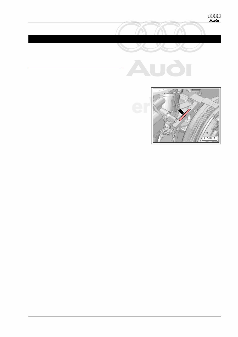
1.1 Engine Number/Engine Specifications
Engine Number
♦ The engine number (“engine code” and “serial number”) are
located at the front of the engine/transmission joint -arrow-.
♦ A sticker with the engine code and serial number is also on the
upper toothed belt guard.
♦ Engine codes beginning with “C” are four letters long.
♦ The first three positions of the engine code stand for displace‐
ment and the mechanical engine structure. They are stamped
in the cylinder block, including the serial number.
♦ The fourth position represents the engine output and torque
and is dependent on the engine control module.
♦ The engine code is on the type plate (market-specific), vehicle
data label and engine control module.
♦ Component locations of the type plate (market-specific) and
vehicle data label. Refer to ⇒ Maintenance ; Booklet 411 .
Engine Specifications. Refer to ⇒ Oil Gauge Tester T40178
Service Values; Rep. Gr. 00 ; Overview - Engine .
Audi A6 2011 ➤ , Audi A6 China 2012 ➤ , Audi A7 Sportback 2011 ➤
4-Cylinder Direct Injection 1.8L; 2.0L Turbo 4V TFSI Engine (Generation II) - Edition 10.2016
1. Identification 1
Protected by copyright. Copying for private or commercial purposes, in part or in whole, is not
permitted unless authorised by AUDI AG. AUDI AG does not guarantee or accept any liability
with respect to the correctness of information in this document. Copyright by AUDI AG.
2 Safety Precautions
⇒ “2.1 Safety Precautions when Working on High-Voltage Vehi‐
cles”, page 2
⇒ “2.2 Safety Precautions when Working on Fuel Supply System”,
page 9
⇒ “2.3 Safety Precautions when Working on Vehicles with Start/
Stop System”, page 9
⇒ “2.4 Safety Precautions when Working on Subframe”,
page 9
⇒ “2.5 Safety Precautions during Road Test with Testing Equip‐
ment”, page 10
⇒ “2.6 Safety Precautions when Working on Ignition System”,
page 10
⇒ “2.7 Safety Precautions when Working on Cooling System”,
page 10
2.1 Safety Precautions when Working on
High-Voltage Vehicles
⇒ “2.1.1 Working on High-Voltage Vehicles”, page 2
⇒ “2.1.2 High-Voltage Components and Cables, Visual Inspection
for Damage”, page 7
2.1.1 Working on High-Voltage Vehicles
WARNING
The engine could start unexpectedly.
For general work performed on the high-voltage vehicle, the
ignition must be switched off and the key must be kept outside
of the vehicle interior.
WARNING
Handling the high-voltage cables:
• Do not support bodyweight on or place tools on the high-
voltage cables and their components. This causes dam‐
age to the insulation.
• Do not sharply bend or kink high-voltage cables as this
causes damage to the insulation.
• The round high-voltage connectors are color coded with
an exterior colored ring and mechanically coded with
guide or code tabs. The codes must be observed when
connecting the round high-voltage connector to avoid me‐
chanical damage to the high-voltage connector.
Audi A6 2011 ➤ , Audi A6 China 2012 ➤ , Audi A7 Sportback 2011 ➤
4-Cylinder Direct Injection 1.8L; 2.0L Turbo 4V TFSI Engine (Generation II) - Edition 10.2016
2 Rep. Gr.00 - General, Technical Data
You're Reading a Preview
What's Included?
Lifetime Access
Access PDF Contents & Bookmarks
Print one or all pages of your manual