

2004 Audi A4 (B6) Service & Repair Manual
What's Included?
Fast Download Speeds
Offline Viewing
Access Contents & Bookmarks
Full Search Facility
Print one or all pages of your manual
Protected by copyright. Copying for private or commercial purposes, in part or in whole, is not
permitted unless authorised by AUDI AG. AUDI AG does not guarantee or accept any liability
with respect to the correctness of information in this document. Copyright by AUDI AG.
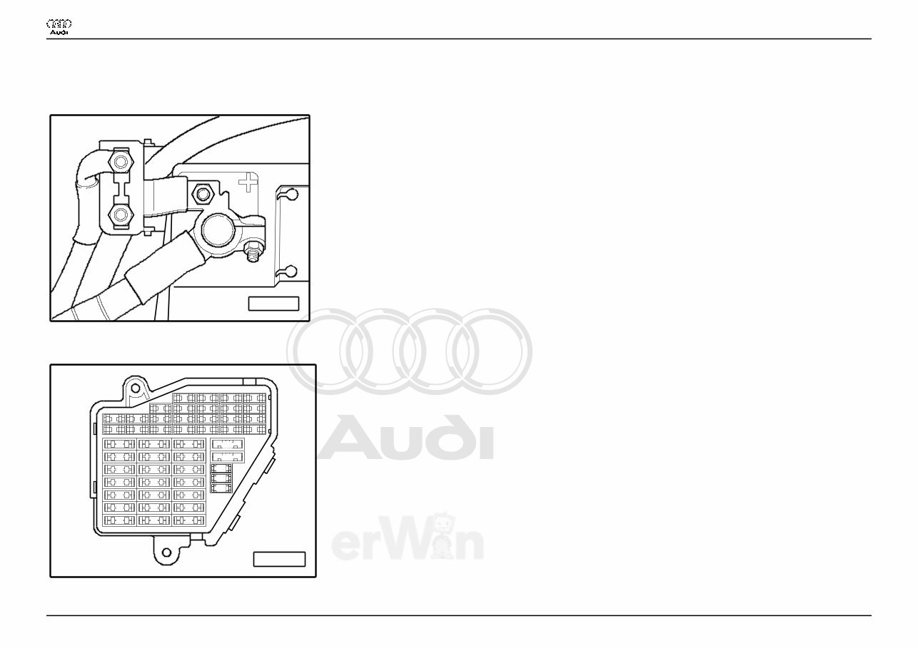
Basic Equipment Lowline
From 2003 m. y.
Main fuse
A97--0220
♦ on the Battery
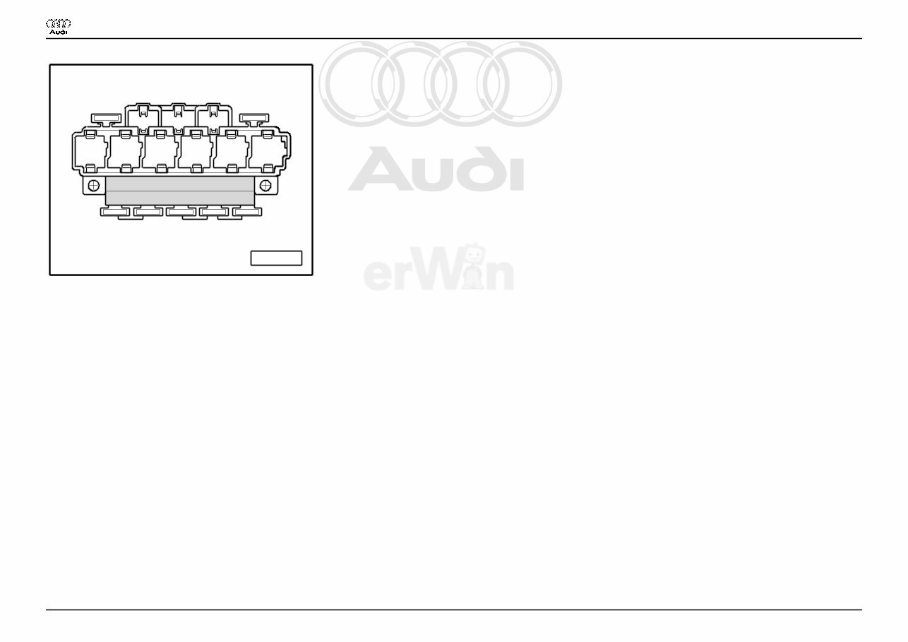
Fuse holder
A97--0242
23 22 21 20
19 18 17 16
15 14 13 12
11 10 9 8
7 6 5
3 4
1 2
44 43 42 41 40
37
39 38
36 35 34 33 32 31
30 29 28 27 26 25 24
Res
Res
Res
Res
Res
Audi A4
Wiring Diagram
No. 3 / 1
12.2005
Protected by copyright. Copying for private or commercial purposes, in part or in whole, is not
permitted unless authorised by AUDI AG. AUDI AG does not guarantee or accept any liability
with respect to the correctness of information in this document. Copyright by AUDI AG.
♦ Instrument panel driver side
Fuse Colors
30 A - Green
25 A - Withe
20 A - Yellow
15 A - Blue
10 A - Red
7,5 A - Brown
5 A - Beige
Note:
♦ Fuse in fusebox from 23 onwards are numbered 223 onwards in Current Flow Diagram.
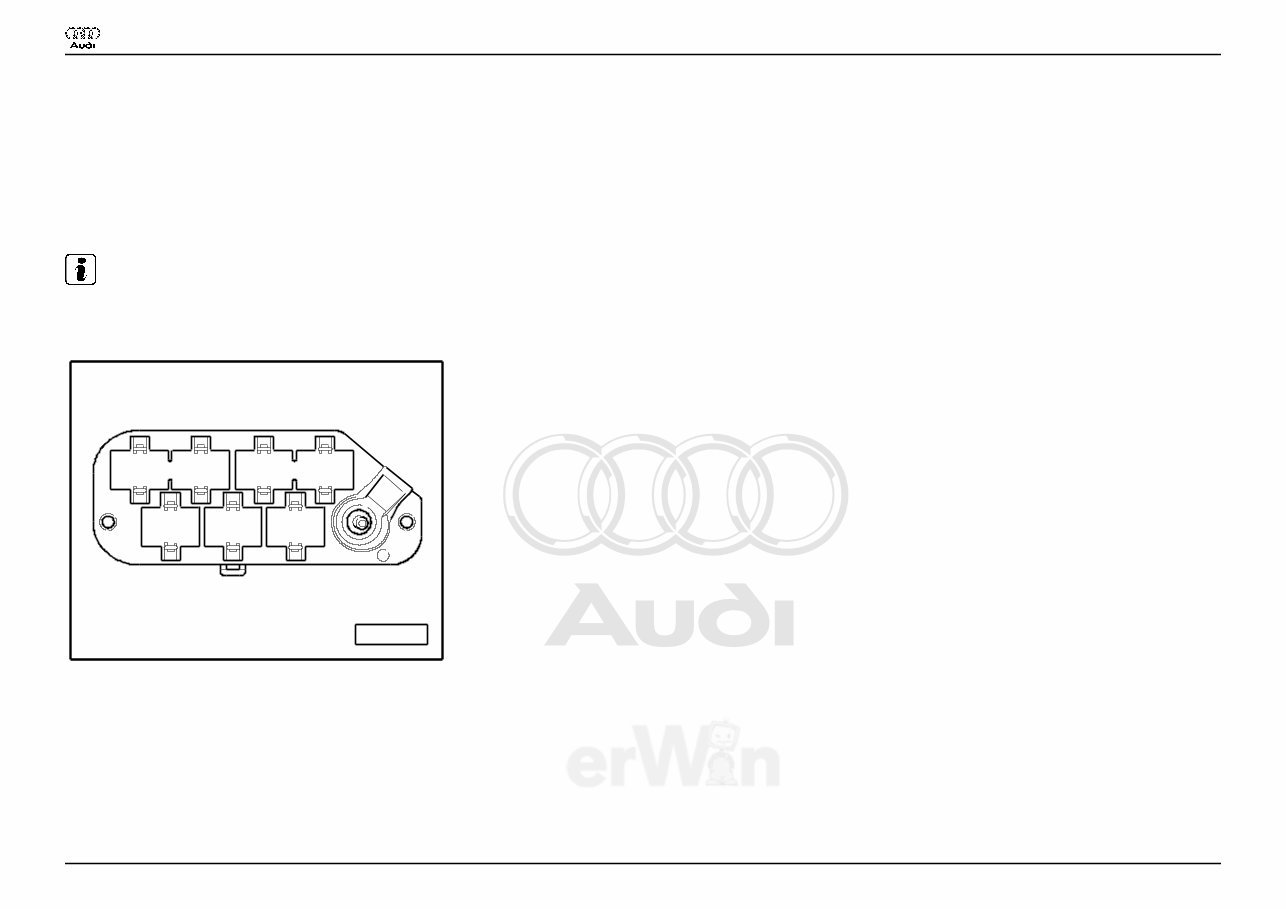
Coupling station with threaded connection
A97--0248
5 6 7
1 2 3 4
♦ in the electronics box, plenum chamber
1 - 10-Pin Connector, black (T10)
2 - 10-Pin Connector, brown (T10a)
3 - 17-Pin Connector, red (T17d)
6 - 17-Pin Connector, white (T17e)
Audi A4
Wiring Diagram
No. 3 / 1
12.2005
Protected by copyright. Copying for private or commercial purposes, in part or in whole, is not
permitted unless authorised by AUDI AG. AUDI AG does not guarantee or accept any liability
with respect to the correctness of information in this document. Copyright by AUDI AG.
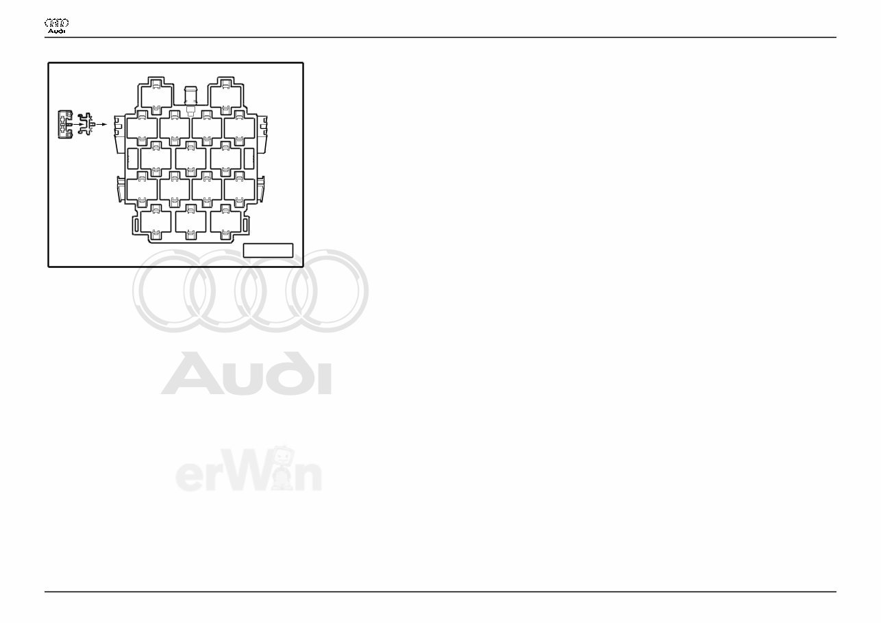
Connector station A-pillar
A97--0247
8
11 12 13 14
2 3
4 5 6 7
10 9
16 15 17
A B
1
♦ behind side trim, left
13 - 10-Pin Connector, violet (T10c)
14 - 10-Pin Connector, grey (T10d)
15 - 17-Pin Connector, green (T17b)
16 - 17-Pin Connector, red (T17a)
17 - 17-Pin Connector, black (T17)
Audi A4
Wiring Diagram
No. 3 / 1
12.2005
Protected by copyright. Copying for private or commercial purposes, in part or in whole, is not
permitted unless authorised by AUDI AG. AUDI AG does not guarantee or accept any liability
with respect to the correctness of information in this document. Copyright by AUDI AG.
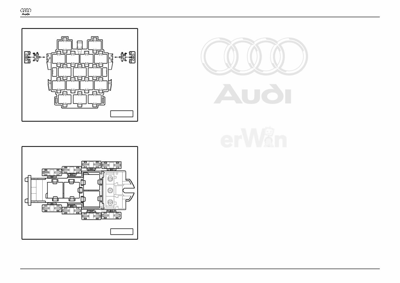
Connector station A-pillar
A97--0400
8
11 12 13 14
2 3
4 5 6 7
10 9
16 15 17
A B
1
C E
D F
♦ behind side trim, right
15 - 17-Pin Connector, red (T17c)
4-Pin Relay Carrier with threaded connection
A97--0245
1 2
3
4
C
B
G
E
F
A
D
H
♦ Instrument panel driver side
Audi A4
Wiring Diagram
No. 3 / 1
12.2005
Protected by copyright. Copying for private or commercial purposes, in part or in whole, is not
permitted unless authorised by AUDI AG. AUDI AG does not guarantee or accept any liability
with respect to the correctness of information in this document. Copyright by AUDI AG.
9-Pin Relay Carrier with Vehicle Electrical System Control Module
A97--0399
8 9 7
A
1
B
2 3 4 5 6
C D E F G
♦ Instrument panel driver side, behind 3-Pin Relay Carrier
3 - Horn Relay (J4)
6 - Load Reduction Relay (J59)
Audi A4
Wiring Diagram
No. 3 / 1
12.2005
You're Reading a Preview
What's Included?
Fast Download Speeds
Offline Viewing
Access Contents & Bookmarks
Full Search Facility
Print one or all pages of your manual
$39.99
Viewed 65 Times Today


Secure transaction
What's Included?
Fast Download Speeds
Offline Viewing
Access Contents & Bookmarks
Full Search Facility
Print one or all pages of your manual
$39.99
The 2004 Audi A4 (B6) Service & Repair Manual is a comprehensive guide designed for both professional mechanics and DIY enthusiasts. It provides detailed instructions and diagrams to help you perform a wide range of repair procedures with confidence.
Key features of this manual include:
- Step-by-step instructions for routine maintenance tasks
- Detailed diagrams and illustrations to enhance understanding of various components and systems
- Comprehensive coverage of major systems, including the engine, transmission, suspension, and electrical systems
- Troubleshooting guides to diagnose and resolve common issues
- Specifications and technical data for quick reference
- An easy-to-follow format that benefits both novice and experienced mechanics
Whether you need to perform a simple oil change or undertake a complex repair, the 2004 Audi A4 (B6) Service & Repair Manual is an invaluable resource that helps you save time and money on maintenance and repairs.


