

Protected by copyright. Copying for private or commercial purposes, in part or in whole, is not
permitted unless authorised by AUDI AG. AUDI AG does not guarantee or accept any liability
with respect to the correctness of information in this document. Copyright by AUDI AG.
Basic Equipment Lowline
From 2003 m. y.
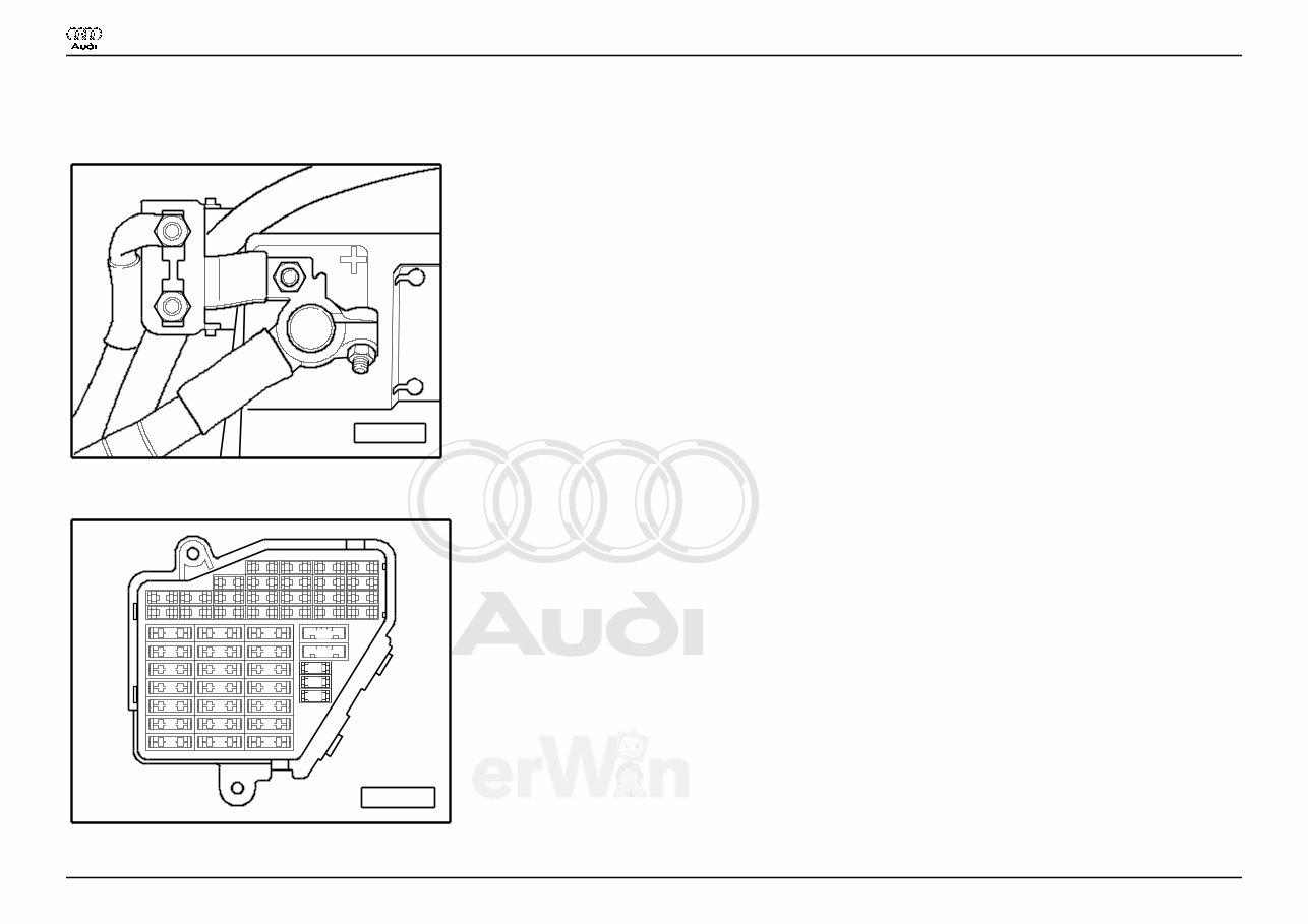
Main fuse
A97--0220
♦ on the Battery
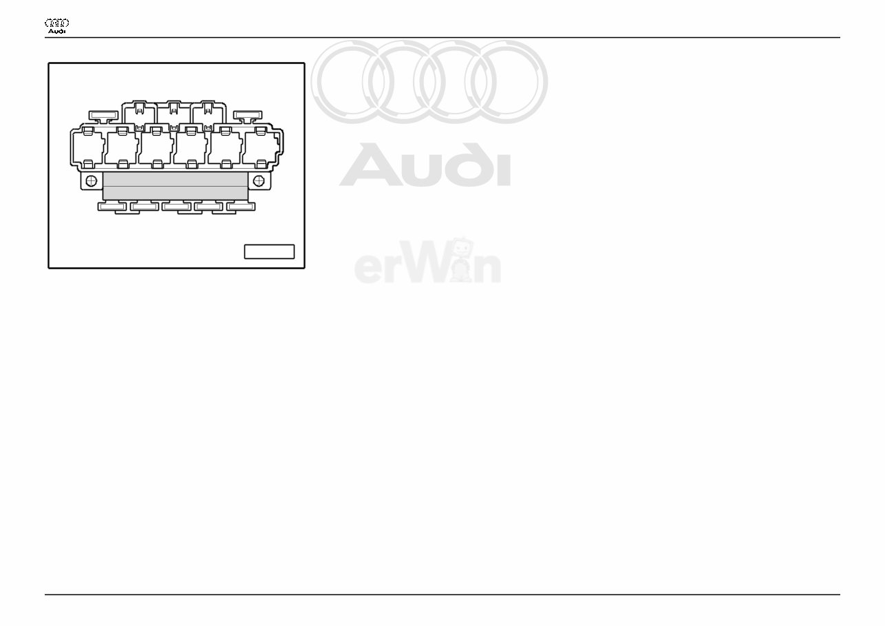
Fuse holder
A97--0242
23 22 21 20
19 18 17 16
15 14 13 12
11 10 9 8
7 6 5
3 4
1 2
44 43 42 41 40
37
39 38
36 35 34 33 32 31
30 29 28 27 26 25 24
Res
Res
Res
Res
Res
Audi A4
Wiring Diagram
No. 3 / 1
12.2005
Protected by copyright. Copying for private or commercial purposes, in part or in whole, is not
permitted unless authorised by AUDI AG. AUDI AG does not guarantee or accept any liability
with respect to the correctness of information in this document. Copyright by AUDI AG.
♦ Instrument panel driver side
Fuse Colors
30 A - Green
25 A - Withe
20 A - Yellow
15 A - Blue
10 A - Red
7,5 A - Brown
5 A - Beige
Note:
♦ Fuse in fusebox from 23 onwards are numbered 223 onwards in Current Flow Diagram.
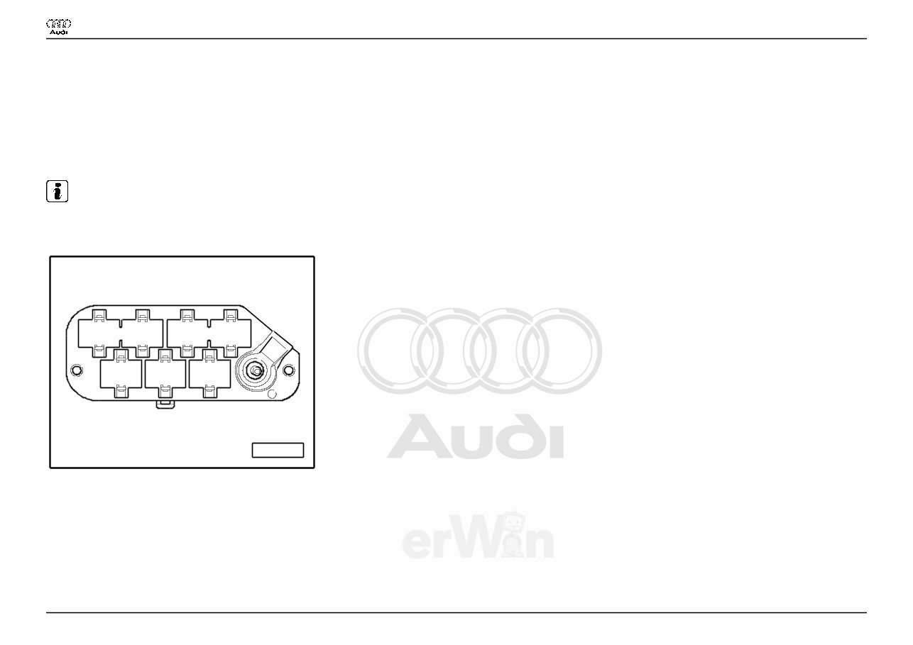
Coupling station with threaded connection
A97--0248
5 6 7
1 2 3 4
♦ in the electronics box, plenum chamber
1 - 10-Pin Connector, black (T10)
2 - 10-Pin Connector, brown (T10a)
3 - 17-Pin Connector, red (T17d)
6 - 17-Pin Connector, white (T17e)
Audi A4
Wiring Diagram
No. 3 / 1
12.2005
Protected by copyright. Copying for private or commercial purposes, in part or in whole, is not
permitted unless authorised by AUDI AG. AUDI AG does not guarantee or accept any liability
with respect to the correctness of information in this document. Copyright by AUDI AG.
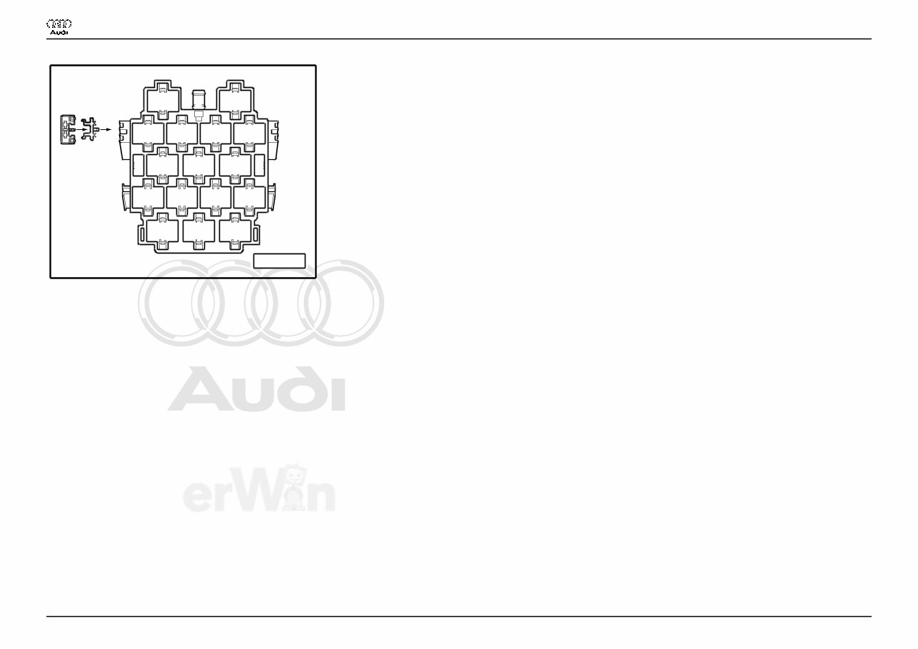
Connector station A-pillar
A97--0247
8
11 12 13 14
2 3
4 5 6 7
10 9
16 15 17
A B
1
♦ behind side trim, left
13 - 10-Pin Connector, violet (T10c)
14 - 10-Pin Connector, grey (T10d)
15 - 17-Pin Connector, green (T17b)
16 - 17-Pin Connector, red (T17a)
17 - 17-Pin Connector, black (T17)
Audi A4
Wiring Diagram
No. 3 / 1
12.2005
Protected by copyright. Copying for private or commercial purposes, in part or in whole, is not
permitted unless authorised by AUDI AG. AUDI AG does not guarantee or accept any liability
with respect to the correctness of information in this document. Copyright by AUDI AG.
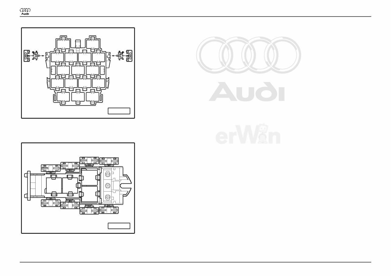
Connector station A-pillar
A97--0400
8
11 12 13 14
2 3
4 5 6 7
10 9
16 15 17
A B
1
C E
D F
♦ behind side trim, right
15 - 17-Pin Connector, red (T17c)
4-Pin Relay Carrier with threaded connection
A97--0245
1 2
3
4
C
B
G
E
F
A
D
H
♦ Instrument panel driver side
Audi A4
Wiring Diagram
No. 3 / 1
12.2005
Protected by copyright. Copying for private or commercial purposes, in part or in whole, is not
permitted unless authorised by AUDI AG. AUDI AG does not guarantee or accept any liability
with respect to the correctness of information in this document. Copyright by AUDI AG.
9-Pin Relay Carrier with Vehicle Electrical System Control Module
A97--0399
8 9 7
A
1
B
2 3 4 5 6
C D E F G
♦ Instrument panel driver side, behind 3-Pin Relay Carrier
3 - Horn Relay (J4)
6 - Load Reduction Relay (J59)
Audi A4
Wiring Diagram
No. 3 / 1
12.2005
You're Reading a Preview
What's Included?
Fast Download Speeds
Offline Viewing
Access Contents & Bookmarks
Full Search Facility
Print one or all pages of your manual
$36.99
2002 Audi A4 Service & Repair Manual Software
Viewed 32 Times Today

What's Included?
Fast Download Speeds
Offline Viewing
Access Contents & Bookmarks
Full Search Facility
Print one or all pages of your manual
$36.99

Secure transaction
What's Included?
Fast Download Speeds
Offline Viewing
Access Contents & Bookmarks
Full Search Facility
Print one or all pages of your manual
Description
Discover the 2002 Audi A4 Service & Repair Manual in PDF format, an indispensable resource for maintaining and fixing your Audi A4. This manual equips you with precise instructions for various tasks, from oil changes to part replacements and issue diagnosis.
- Model: 2002 Audi A4
- Year: 2002
Key features of the 2002 Audi A4 Service & Repair Manual include:
- Step-by-step instructions
- Clear diagrams and illustrations
- Troubleshooting tips and techniques
- Diagnostic procedures
- Regular maintenance schedules
- Easy-to-follow format
Whether you're a professional mechanic or a DIY enthusiast, this manual is an invaluable tool that can help you save both time and money. Bid farewell to hefty repair costs and welcome a well-maintained Audi A4.
Enhance your Audi A4's durability and performance by acquiring the 2002 Audi A4 Service & Repair Manual in PDF format today.


