


Tektronix
7
Service Manual
2232
Digital Storage Oscilloscope
Serial Numbers B010100 to B029999
070-7067-01
Warning
The servicing instructions are for use by qualified
personnel only. To avoid personal injury, do not
perform any servicing unless you are qualified to
do so. Refer to the Safety Summary prior to
performing service.
Please check for change information
at the rear of this manual.
First Printing: June 1992

Copyright E Tektronix, Inc. 1989, 1992. All rights reserved.
Tektronix products are covered by U.S. and foreign patents, issued and pending. Information in this publication supercedes
that in all previously published material. Specifications and price change privileges reserved.
Printed in the U.S.A.
Tektronix, Inc., P.O. Box 1000, Wilsonville, OR 970701000
TEKTRONIX and TEK are registered trademarks of Tektronix, Inc.

WARRANTY
Tektronix warrants that this product will be free from defects in materials and workmanship for a period of three
(3) years from the date of shipment. If any such product proves defective during this warranty period, Tektronix,
at its option, either will repair the defective product without charge for parts and labor, or will provide a
replacement in exchange for the defective product.
In order to obtain service under this warranty, Customer must notify Tektronix of the defect before the expiration
of the warranty period and make suitable arrangements for the performance of service. Customer shall be
responsible for packaging and shipping the defective product to the service center designated by Tektronix, with
shipping charges prepaid. Tektronix shall pay for the return of the product to Customer if the shipment is to a
location within the country in which the Tektronix service center is located. Customer shall be responsible for
paying all shipping charges, duties, taxes, and any other charges for products returned to any other locations.
This warranty shall not apply to any defect, failure or damage caused by improper use or improper or inadequate
maintenance and care. Tektronix shall not be obligated to furnish service under this warranty a) to repair damage
resulting from attempts by personnel other than Tektronix representatives to install, repair or service the product;
b) to repair damage resulting from improper use or connection to incompatible equipment; or c) to service a
product that has been modified or integrated with other products when the effect of such modification or
integration increases the time or difficulty of servicing the product.
THIS WARRANTY IS GIVEN BY TEKTRONIX WITH RESPECT TO THIS PRODUCT IN LIEU OF
ANY OTHER WARRANTIES, EXPRESSED OR IMPLIED. TEKTRONIX AND ITS VENDORS
DISCLAIM ANY IMPLIED WARRANTIES OF MERCHANTABILITY OR FITNESS FOR A
PARTICULAR PURPOSE. TEKTRONIX RESPONSIBILITY TO REPAIR OR REPLACE DEFECTIVE
PRODUCTS IS THE SOLE AND EXCLUSIVE REMEDY PROVIDED TO THE CUSTOMER FOR
BREACH OF THIS WARRANTY. TEKTRONIX AND ITS VENDORS WILL NOT BE LIABLE FOR ANY
INDIRECT, SPECIAL, INCIDENTAL, OR CONSEQUENTIAL DAMAGES IRRESPECTIVE OF
WHETHER TEKTRONIX OR THE VENDOR HAS ADVANCE NOTICE OF THE POSSIBILITY OF
SUCH DAMAGES.

LISTOFILLUSTRATIONS
LISTOFTABLES
OPERATORSSAFETYSUMMARY
SERVICINGSAFETYSUMMARY
2232Service
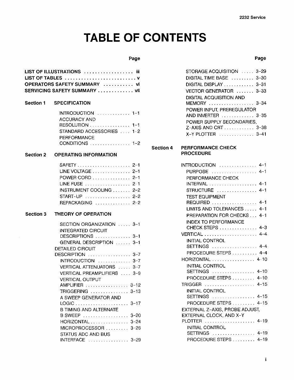
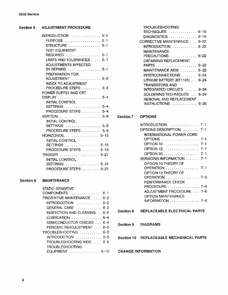
TABLEOFCONTENTS
SPECIFICATION
INTRODUCTION.............
ACCURACYAND
RESOLUTION................
STANDARDACCESSORIES....
PERFORMANCE
CONDITIONS................
OPERATINGINFORMATION
POWERCORD...............
LINEFUSE..................
INSTRUMENTCOOLING.......
START-UP..............004.
REPACKAGING..............
THEORYOFOPERATION
SECTIONORGANIZATION.....
INTEGRATEDCIRCUIT
DESCRIPTIONS..............
GENERALDESCRIPTION......
DETAILEDCIRCUIT
DESCRIPTION.................
INTRODUCTION.............
VERTICALATTENUATORS.....
VERTICALPREAMPLIFIERS....
VERTICALOUTPUT
AMPLIFIER.................
TRIGGERING...............
ASWEEPGENERATORAND
BTIMINGANDALTERNATE
BSWEEP..................
HORIZONTAL.........-..--.
MICROPROCESSOR.........
STATUSADCANDBUS
INTERFACE................
Page
STORAGEACQUISITION.....3-29
DIGITALTIMEBASE.........3-30
DIGITALDISPLAY............3-31
VECTORGENERATOR.......3-33
DIGITALACQUISITIONAND
MEMORY.............2005-3-34
POWERINPUT,PREREGULATOR
ANDINVERTER.............3-35
POWERSUPPLYSECONDARIES,
Z-AXISANDCRT............3-38
X-YPLOTTER..............3-41
PERFORMANCECHECK
PROCEDURE
INTRODUCTION...............4-1
PURPOSE..................4-1
PERFORMANCECHECK
INTERVAL...............000-4-1
STRUCTURE................4-1
TESTEQUIPMENT
REQUIRED..................4-1
LIMITSANDTOLERANCES.....4-1
PREPARATIONFORCHECKS...4-1
INDEXTOPERFORMANCE
CHECKSTEPS...............4-3
VERTICAL.............2.-2.048.4-4
INITIALCONTROL
SETTINGS..................4-4
PROCEDURESTEPS..........4-4
HORIZONTAL...........--.-654-10
INITIALCONTROL
SETTINGS.................4-10
PROCEDURESTEPS.........4-10
TRIGGER..............0.0005-4-15
INITIALCONTROL
SETTINGS...............-.4-15
PROCEDURESTEPS.........4-15
EXTERNALZ-AXIS,PROBEADJUST,
EXTERNALCLOCK,ANDX-Y
PLOTTER..........-.-.--0005-4-19
INITIALCONTROL
SETTINGS.................4-19
PROCEDURESTEPS.........4-19
2232Service
Section5
Section6
ADJUSTMENTPROCEDURE
INTRODUCTION...............5-1
PURPOSE..................5-1
STRUCTURE................5-1
TESTEQUIPMENT
REQUIRED..................5-1
LIMITSANDTOLERANCES.....5-1
ADJUSTMENTSAFFECTED
BYREPAIRS.................5-1
PREPARATIONFOR
ADJUSTMENT...............5-2
INDEXTOADJUSTMENT
PROCEDURESTEPS..........5-3
POWERSUPPLYANDCRT
DISPLAY..........0.0.0.eae5-4
INITIALCONTROL
SETTINGS...............0..5-4
PROCEDURESTEPS..........5-4
VERTICAL..............-.--04-5-6
INITIALCONTROL
SETTINGS..................5-6
PROCEDURESTEPS..........5-6
HORIZONTAL.........-..-.--.5-15
INITIALCONTROL
SETTINGS.................5-15
PROCEDURESTEPS.........5-15
TRIGGER....................5-21
INITIALCONTROL
SETTINGS..............0..5-21
PROCEDURESTEPS.........5-21
MAINTENANCE
STATIC-SENSITIVE
COMPONENTS................6-1
PREVENTIVEMAINTENANCE.....6-2
INTRODUCTION.............6-2
GENERALCARE.............6-2
INSPECTIONANDCLEANING..6-2
LUBRICATION...............6-4
SEMICONDUCTORCHECKS...6-4
PERIODICREADJUSTMENT....6-5
TROUBLESHOOTING...........6-5
INTRODUCTION.............6-5
TROUBLESHOOTINGAIDS....6-5
TROUBLESHOOTING
EQUIPMENT................6-10
Section7
Section8
Section9
TROUBLESHOOTING
TECHNIQUES..............6-10
DIAGNOSTICS..............6-15
CORRECTIVEMAINTENANCE...6-22
INTRODUCTION............6-22
MAINTENANCE
PRECAUTIONS.............6-22
OBTAININGREPLACEMENT
PARTS.......0.cee ceceeees6-22
MAINTENANCEAIDS........6-22
INTERCONNECTIONS........6-24
LITHIUMBATTERY(BT1101)...6-24
TRANSISTORSAND
INTEGRATEDCIRCUITS......6-24
SOLDERINGTECHNIQUES...6-24
REMOVALANDREPLACEMENT
INSTRUCTIONS.............6-26
OPTIONS
INTRODUCTION...............7-1
OPTIONSDESCRIPTION........7-1
INTERNATIONALPOWERCORD
OPTIONS...........0..0000-7-1
OPTION10.........00.. 0000.7-1
OPTION12.........0..00000-7-1
OPTION33..........0..0000 8:7-1
SERVICINGINFORMATION.......7-1
OPTION10THEORYOF
OPERATION.............-0-7-1
OPTION12THEORYOF
OPERATION..............0--7-3
PERFORMANCECHECK
PROCEDURE................7-4
ADJUSTMENTPROCEDURE...7-6
OPTIONMAINTENANCE
INFORMATION...........-..-7-6
REPLACEABLEELECTRICALPARTS
DIAGRAMS
Section10REPLACEABLEMECHANICALPARTS
CHANGEINFORMATION
2232Service
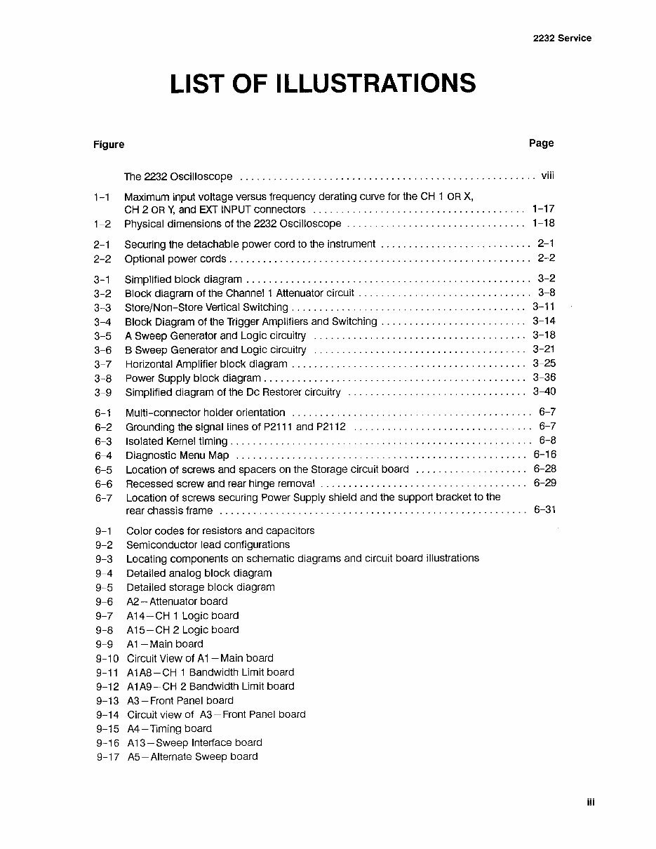
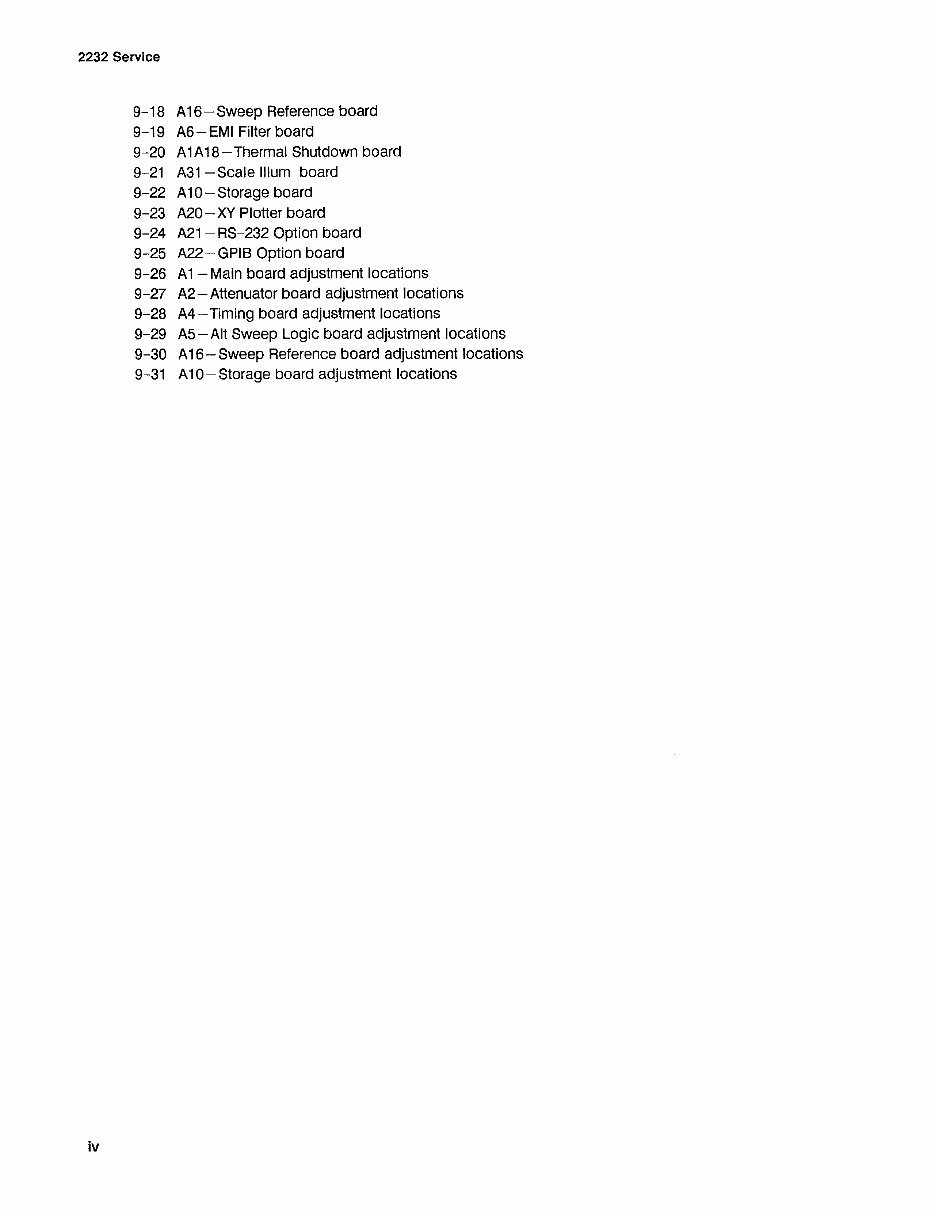
LISTOFILLUSTRATIONS
FigurePage
The2232OscillOSCOPe...1...ee eeeeensviii
1-1MaximuminputvoltageversusfrequencyderatingcurvefortheCH1ORX,
CH2ORY,andEXTINPUTconnectors.........0.0.00.ceeeee1-17
1-2Physicaldimensionsofthe2232Oscilloscope......0.0.0...eeeeee1-18
2-1Securingthedetachablepowercordtotheinstrument............ 0.0...eeeeee2-1
2-2OptionalpowerCOMdS.......eee eeetenes2-2
3-1Simplifiedblockdiagram.....6... eeeeeeeens3-2
3-2BlockdiagramoftheChannel1Attenuatorcircuit...2.0.2... eee3-8
3-3Store/Non-StoreVerticalSwitching.........0..000. 00.cccceeeee3-11
3-4BlockDiagramoftheTriggerAmplifiersandSwitching................. 0.ceceeee3-14
3-5ASweepGeneratorandLogicCircuitry1.0.00... .eeeeee3-18
3-6BSweepGeneratorandLogiccircuitry......0... eee3-21
3-7HorizontalAmplifierblockdiagram...........0.0...ees3-25
3-8PowerSupplyblockdiagram....2.0...eeeteens3-36
3-9SimplifieddiagramoftheDcRestorercircuitry........... 00.0.eeeeeeeee3-40
6-1Multi-connectorholderorientation.........2... eee6-7
6-2GroundingthesignallinesofP2111andP2112«1...ee eee6-7
6-3IsolatedKerneltiming..........20.0....eeeneeteens6-8
6-4DiagnosticMenuMap...........2...eeeentenes6-16
6-5LocationofscrewsandspacersontheStorageCircuitboard................046.6-28
6-6Recessedscrewandrearhingeremoval........... 2.0.0ceeeeeeee6-29
6-7LocationofscrewssecuringPowerSupplyshieldandthesupportbrackettothe
rearChassisfraMe..2...eeteeeeeeens6-31
9-1Colorcodesforresistorsandcapacitors
9-2Semiconductorleadconfigurations
9-3Locatingcomponentsonschematicdiagramsandcircuitboardillustrations
9-4Detailedanalogblockdiagram
9-5Detailedstorageblockdiagram
9-6A2—Attenuatorboard
9-7A14—CH1Logicboard
9-8A1i5—CH2Logicboard
9-9A1—Mainboard
9-10CircuitViewofAl—Mainboard
9-11A1A8—CH1BandwidthLimitboard
9-12A1A9—CH2BandwidthLimitboard
9-13A3—FrontPanelboard
9-14CircuitviewofA3—FrontPanelboard
9-15A4—Timingboard
9-16A13—SweepInterfaceboard
9-17A5S—AlternateSweepboard
2232Service
9-18
9-19
9-20
9-21
9-22
9-23
9-24
9-25
9-26
9-27
9-28
9-29
9-30
9-31
A16—SweepReferenceboard
A6—EMIFilterboard
A1A18—ThermalShutdownboard
A31—ScaleIllumboard
A10—Storageboard
A20—XYPlotterboard
A21—RS-232Optionboard
A22—GPIBOptionboard
A1—Mainboardadjustmentlocations
A2—Attenuatorboardadjustmentlocations
A4—Timingboardadjustmentlocations
A5—AltSweepLogicboardadjustmentlocations
A16—SweepReferenceboardadjustmentlocations
A10—Storageboardadjustmentlocations
2232Service
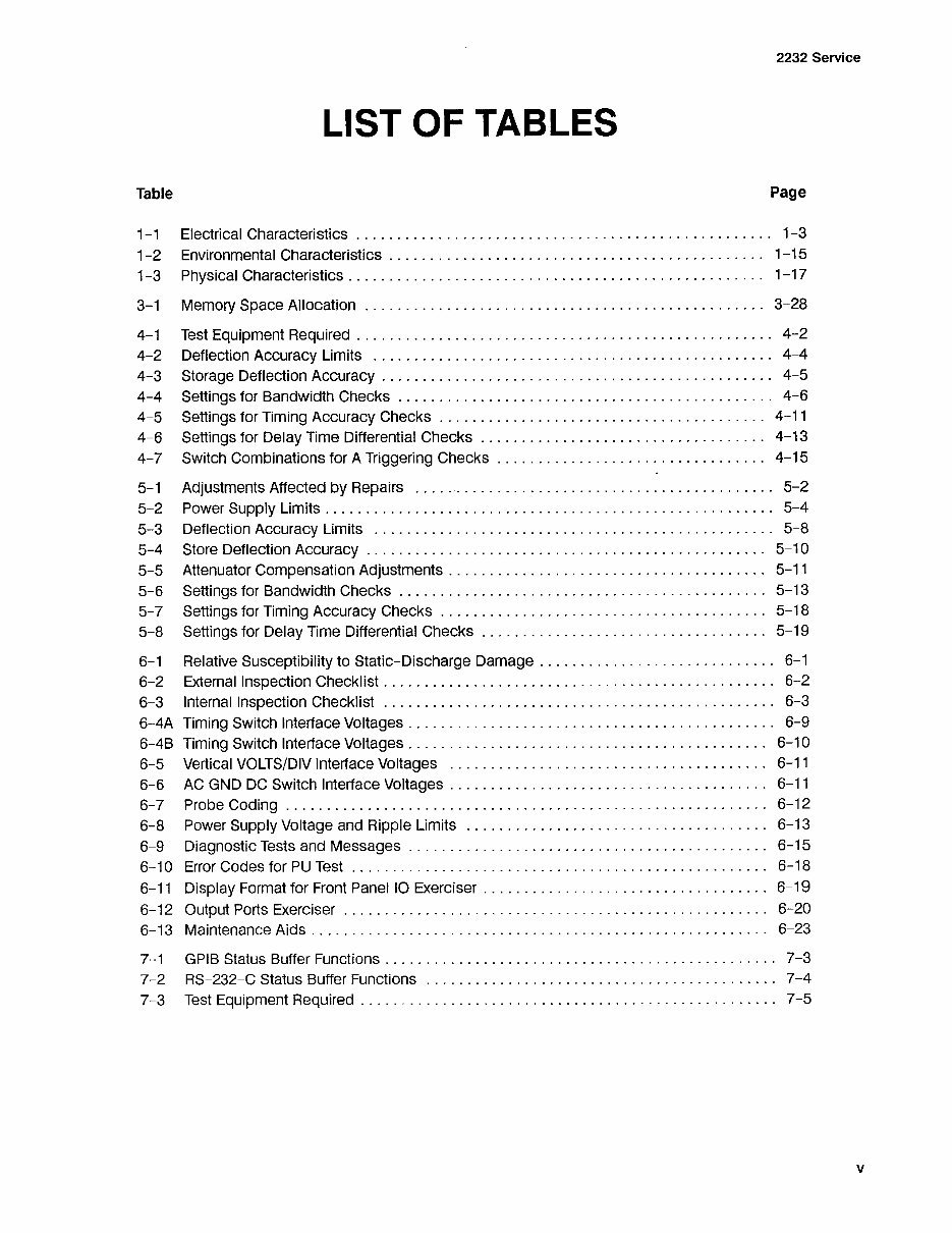
LISTOFTABLES
TablePage
1-1ElectricalCharacteristics......0.0... eeeens1-3
1-2EnvironmentalCharacteristics....0.0.0....ceeeeeeteens1-15
1-3PhysicalCharacteristics.........0.0...eee eens1-17
3-1MemorySpaceAllocation.........0.0...ce eeeeee3-28
4-1TestEquipmentRequired........0... eetenes4-2
4-2DeflectionAccuracyLimits..........0...0ceeeeteens4-4
4-3StorageDeflectionAccuracy........0.0...beeen ene4-5
4-4SettingsforBandwidthChecks........0...2.eteeens4-6
4-5SettingsforTimingAccuracyChecks.....0.0...cee eeeee4-11
4-6SettingsforDelayTimeDifferentialChecks.......... 0.2...0.ceeeeeeee4-13
4-7SwitchCombinationsforATriggeringChecks........... 0...0cceeeee4-15
5-1AdjustmentsAffectedbyRepairs.....eee tneeeeeeeeee5-2
5-2PowerSupplyLimits........0.0.0.eee5-4
5-3DeflectionAccuracyLimits.........0...eee nee5-8
5-4StoreDeflectionAccuracy........0.6...cetees5-10
5-5AttenuatorCompensationAdjustments..........0.000...eeeees5-11
5-6SettingsforBandwidthChecks.............0 0.teeneee5-13
5-7SettingsforTimingAccuracyChecks........... 0.0...eeeeee5-18
5-8SettingsforDelayTimeDifferentialChecks............ 0.0.0.0.ceeeecece5-19
6-1RelativeSusceptibilitytoStatic-DischargeDamage...............-.. 0ceeee6-1
6-2ExternalInspectionChecklist........00.002eeeeetenes6-2
6-3InternalInspectionChecklist...........00...ceeeeetees6-3
6-4ATimingSwitchInterfaceVoltages.....0.0...ceeeee6-9
6-4BTimingSwitchInterfaceVoltages..2... eteeens6-10
6-5VerticalVOLTS/DIVInterfaceVoltages....0... eeeee6-11
6-6ACGNDDCSwitchInterfaceVoltages............. 0...ceeeee6-11
6-7ProbeCoding...1...6.ccneeeeeeeeee6-12
6-8PowerSupplyVoltageandRippleLimits.........0...0.eee eeeee6-13
6-9DiagnosticTestsandMessages......2...teens6-15
6-10ErrorCodesforPUTest.........0...eeeeeeeeeee6-18
6-11DisplayFormatforFrontPanelIOExerciser.......... 2.0.0...eeececeeee6-19
6-12OutputPortsExerciser...0.00.00... eeeeeeeeens6-20
6-13MaintenanceAidS.........0.0... eeeens6-23
7-1GPIBStatusBufferFunctions..........00.0.0eee eens7-3
7-2RS-232-CStatusBufferFUNCTIONS...2... eee7-4
7-3TestEquipmentRequired...........20.0... eeeens7-5
2232Service
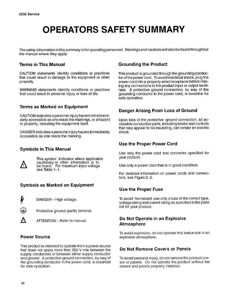
OPERATORSSAFETYSUMMARY
Thesafetyinformationinthissummaryisforoperatingpersonnel.Warningsandcautionswillalsobefoundthroughout
themanualwheretheyapply.
TermsinThisManual
CAUTIONstatementsidentifyconditionsorpractices
thatcouldresultindamagetotheequipmentorother
property.
WARNINGstatementsidentifyconditionsorpractices
thatcouldresultinpersonalinjuryorlossoflife.
TermsasMarkedonEquipment
CAUTIONindicatesapersonalinjuryhazardnotimmedi-
atelyaccessibleasonereadsthemarkings,orahazard
toproperty,includingtheequipmentitself.
DANGERindicatesapersonalinjuryhazardimmediately
accessibleasonereadsthemarking.
SymbolsinThisManual
Thissymbolindicateswhereapplicable
cautionaryorotherinformationisto
befound.Formaximuminputvoltage
seeTable1-1.
SymbolsasMarkedonEquipment
yDANGER—Highvoltage.
a)Protectiveground(earth)terminal.
AATTENTION—Refertomanual.
PowerSource
Thisproductisintendedtooperatefromapowersource
thatdoesnotapplymorethan250Vrmsbetweenthe
supplyconductorsorbetweeneithersupplyconductor
andground.Aprotectivegroundconnection,bywayof
thegroundingconductorinthepowercord,isessential
forsafeoperation.
vi
GroundingtheProduct
Thisproductisgroundedthroughthegroundingconduc-
torofthepowercord.Toavoidelectricalshock,plugthe
powercordintoaproperlywiredreceptaclebeforemak-
inganyconnectionstotheproductinputoroutputtermi-
nals.Aprotectivegroundconnection,bywayofthe
groundingconductorinthepowercord,isessentialfor
safeoperation.
DangerArisingFromLossofGround
Uponlossoftheprotective-groundconnection,allac-
cessibleconductiveparts,includingknobsandcontrols
thatmayappeartobeinsulating,canrenderanelectric
shock.
UsetheProperPowerCord
Useonlythepowercordandconnectorspecifiedfor
yourproduct.
Useonlyapowercordthatisingoodcondition.
Fordetailedinformationonpowercordsandconnec-
tors,seeFigure2-2.
UsetheProperFuse
Toavoidfirehazard,useonlyafuseofthecorrecttype,
voltageratingandcurrentratingasspecifiedintheparts
listforyourproduct.
DoNotOperateinanExplosive
Atmosphere
Toavoidexplosion,donotoperatethisinstrumentinan
explosiveatmosphere.
DoNotRemoveCoversorPanels
Toavoidpersonalinjury,donotremovetheproductcov-
ersorpanels.Donotoperatetheproductwithoutthe
coversandpanelsproperlyinstalled.
You're Reading a Preview
What's Included?
Fast Download Speeds
Online & Offline Access
Access PDF Contents & Bookmarks
Full Search Facility
Print one or all pages of your manual
$27.99
Tektronix 2232 Service Manual
Viewed 22 Times Today

What's Included?
Fast Download Speeds
Online & Offline Access
Access PDF Contents & Bookmarks
Full Search Facility
Print one or all pages of your manual
$27.99

Secure transaction
What's Included?
Fast Download Speeds
Online & Offline Access
Access PDF Contents & Bookmarks
Full Search Facility
Print one or all pages of your manual
Description
This is a scan of the Service Manual for the Tektronix Model 2232 Oscilloscope. The pages are legible and suitable for their intended purpose. You can check out the sample, as it is drawn directly from the product you will receive, and does include examples of any poorer quality pages so you can make an informed buying decision.
Please note that we have thousands of manuals available, most of which are of superb quality. If there is a piece of equipment you need a manual for, just email us and if we have it we will put it up here for your consideration. Thank you!


