


SERVICE
HANDBOOK
REVISION 0
COPYRIGHT © 1996 CANON INC. CANON GP215/200 REV.0 JULY 1996 PRINTED IN JAPAN (IMPRIME AU JAPON)
JULY 1996 FY8-23AM-000
Downloaded from www.Manualslib.com manuals search engine

COPYRIGHT © 1996 CANON INC.
Printed in Japan
Imprimé au Japon
Use of this manual should be
strictly supervised to avoid
disclosure of confidential
information.
COPYRIGHT © 1996 CANON INC. CANON GP215/200 REV.0 JULY 1996 PRINTED IN JAPAN (IMPRIME AU JAPON)
IMPORTANT
THE INFORMATION CONTAINED HEREIN IS PUBLISHED BY CANON, INC., JAPAN, AND IS
FOR REFERENCE USE ONLY. SPECIFICATIONS AND OTHER INFORMATION CONTAINED
HEREIN MAY VARY SLIGHTLY FROM ACTUAL MACHINE VALUES OR THOSE FOUND IN
ADVERTISING AND OTHER PRINTED MATTER.
ANY QUESTIONS REGARDING INFORMATION CONTAINED HEREIN SHOULD BE DIRECTED
TO THE COPIER SERVICE DEPARTMENT OF THE SALES COMPANY.
Prepared by
OFFICE IMAGING PRODUCTS TECHNICAL SUPPORT DEPARTMENT 1
OFFICE IMAGING PRODUCTS TECHNICAL SUPPORT DIVISION
CANON INC.
30-2, Shimomaruko 3-chome, Ohta-ku, Tokyo 146 Japan
Downloaded from www.Manualslib.com manuals search engine
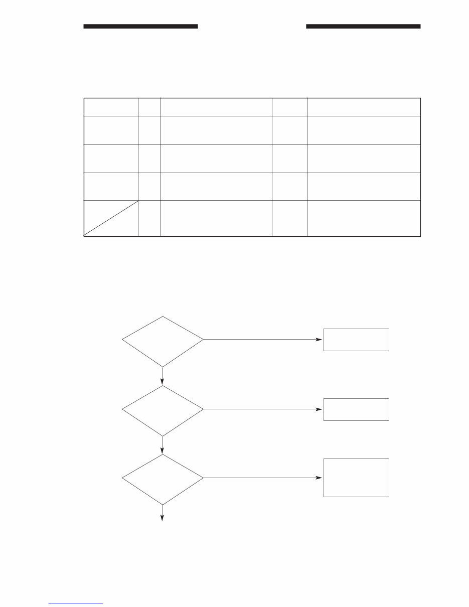
In this Handbook, work procedures are given in the form of tables instead of flow charts used general-
ly. Familiarize yourself by studying the example below.
EX. AC power is absent.
■ To find out the cause (problem part) of a single problem, refer to the item under “Cause/Fault.” For “AC
power is absent,” the cause may be the power plug, covers, power source, or others.
■ To find out the checks to make or remedies to provide for a single problem, refer to the “Checks” and
“Remedies”; make checks, answer to the questions YES or NO, and provide remedies accordingly. If
the answer is otherwise, proceed to the next step.
■ Checks on the voltage using a meter call for special note; the description “Check the voltage between
J109-1 (+) and J109-2 (–) on the DC controller PCB” means that the positive probe of the meter should
be placed on J109-1 (+) and the negative probe, on J109-2 (–).
Are the front door
and delivery cover
closed properly?
Is the rated voltage
present at the power
outlet?
Is the power plug
connected to the
power outlet?
<Check> <Answer> <Answer> <Remedies>
1
<Step>
2
3
YES
NO
NO
NO
YES
YES
Connect the power
plug.
Close the door or
the cover.
The problem is not
of copier. Advise
the customer as
such.
i
Guide To Tables
Cause/Fault
Power plug
Covers
Power source
Step
1
2
3
4
Answer
NO
NO
NO
YES
Check
Is the power plug connected to
the power outlet?
Are the front door and delivery
cover closed properly?
Is the rated voltage present at
the power outlet?
Is the rated voltage present
between J1-1 and -2 (near cord
plate)?
Remedies
Connect the power plug
Close the door or the cover
The problem is not of the copier.
Advise the customer as such.
Go to step 6.
Downloaded from www.Manualslib.com manuals search engine

Downloaded from www.Manualslib.com manuals search engine

CONTENTS
iii
CHAPTER 1 MAINTENANCE AND INSPECTION
A. IMAGE BASIC ADJUSTMENT
PROCEDURE ..........................................1-1
B. POINTS TO NOTE FOR SCHEDULED
SERVICING .............................................1-2
CHAPTER 2 STANDARDS AND ADJUSTMENTS
A. MECHANICAL .........................................2-1 B. ELECTRICAL SYSTEM.........................2-10
CHAPTER 3 TROUBLESHOOTING IMAGE
PROBLEMS
A. INITIAL CHECKS ....................................3-1
B. SAMPLE IMAGE FAULTS .......................3-4
C. TROUBLESHOOTING IMAGE
FAULTS ....................................................3-5
CHAPTER 4 TROUBLESHOOTING MALFUNCTIONS
1
2
3
4
5
6
7
8
1. E000 (Fixing temperature fails to rise.) ...4-1
2. E001 (Fixing temperature is abnormally
high.) ........................................................4-2
3. E002/E003 (Fixing temperature is
abnormally high.) .....................................4-2
4. E007 (The fixing film has become
displaced.) ...............................................4-3
5. E007-01 (The fixing film fails to return.)...4-4
6. E010 (The main motor fails to lock.) .......4-5
7. E030 (The total copy counter fails to
operate.) ..................................................4-5
8. E031 (The fax counter fails to operate.) ......4-5
9. E032 (The copy data controller counter
is faulty.) ...................................................4-6
10. E051 (The horizontal registration home
position detection mechanism is faulty.) ....4-6
11. E064 (The high-voltage output is faulty.) .....4-7
12. E100 (BD error) .......................................4-8
13. E110 (The laser scanner motor fails to
lock.) ........................................................4-9
14. E190 (RAM error) ....................................4-9
15. E191 (error in serial communication
between DC controller PCB and
composite power supply PCB ...............4-10
16. E202 (Scanner home position is not
detected; no code indication is made.)..4-11
17. E220 (The scanning lamp turns ON
wrongly.).................................................4-11
18. E240 (error in communication between
DC controller PCB and image
processor PCB) .....................................4-12
19. E243 (error in communication between
control panel and image processor
PCB.) .....................................................4-12
20. E261 (zero cross error) .........................4-13
21. E310 (The scanning lamp is poorly
adjusted.) ...............................................4-13
22. E710, E711, E712, E713, E716 (IPC
communication error) .............................4-14
23. E717 (error in communication with
Copy Data Controller) ............................4-14
24. E803 (composite power supply PCB
24V output error) ...................................4-14
25. AC power is absent................................4-15
26. DC power is absent. ..............................4-16
27. The photosensitive drum fails to rotate..4-17
28. Pick-up fails. (pick-up from the
cassette) ................................................4-17
29. The lifter fails to move up. .....................4-18
30. Pick-up fails. (multifeeder)......................4-18
31. The registration roller fails to rotate.......4-19
Downloaded from www.Manualslib.com manuals search engine

iv
CHAPTER 7 SERVICE MODE
A. OUTLINE .................................................7-1
B. USING SERVICE MODE.........................7-2
C. USING ADJUSTMENT MODE AND
SETTINGS MODE ...................................7-3
D. *1* DISPLAY (CONTROL DISPLAY MODE)
.................................................................7-4
E. *2* I/O DISPLAY (I/O DISPLAY MODE)
...............................................................7-21
F. *3* ADJUST (ADJUSTMENT MODE) ...7-40
G. *4* FUNCTION (FUNCTION MODE) ....7-51
H. *5* OPTIN (SETTINGS MODE) ............7-71
I. *6* COUNTER (COUNTER MODE) ......7-77
J. *7* ACC (ACCESSORY MODE)............7-81
CHAPTER 8 SELF DIAGNOSIS
A. COPIER ...................................................8-1
B. SELF DIAGNOSIS OF THE RDF-G1 ......8-6
C. SELF DIAGNOSIS OF THE ADF-F1.......8-6
D. SELF DIAGNOSIS OF THE
PEDESTAL ..............................................8-7
E. SELF DIAGNOSIS OF THE MULTI
OUTPUT TRAY -C1.................................8-7
F. SELF DIAGNOSIS OF THE MULTI
OUTPUT TRAY-12 ...................................8-8
APPENDIX
A. GENERAL TIMING CHART ....................A-1
B. SIGNALS AND ABBREVIATIONS ..........A-2
C. GENERAL CIRCUIT DIAGRAM..............A-3
D. SPECIFICATIONS...................................A-7
E. LIST OF SPECIAL TOOLS ...................A-13
F. SOLVENTS/OILS ..................................A-14
CHAPTER 5 TROUBLESHOOTING FEEDING FAULTS
A. COPY PAPER JAMS ...............................5-1 B. FEEDING FAULTS...................................5-6
A. CLUTCHES AND SOLENOIDS...............6-2
B. MOTORS .................................................6-4
C. FANS .......................................................6-6
D. SENSORS ...............................................6-8
E. SWITCHES AND COUNTERS..............6-10
F. PCBS .....................................................6-12
G. FAX-RELATED PCBS............................6-14
H. VARIABLE RESISTORS (VR), LIGHT-
EMITTING DIODES (LED), AND CHECK
PINS BY PCB ........................................6-16
CHAPTER 6 ARRANGEMENT AND FUNCTIONS OF
ELECTRICAL PARTS
32. The scanner fails to move forward/in
reverse. ..................................................4-19
33. The pre-exposure lamp fails to turn ON. .4-20
34. The scanning lamp fails to turn ON. ......4-20
35. The fixing heater fails to operate. ..........4-21
36. The counter fails to operate. ...................4-21
37. The Add Paper message fails to turn
OFF . .......................................................4-22
38. The Jam message fails to turn OFF . .....4-22
39. The Add Toner message fails to turn
OFF . .......................................................4-22
40. The fax error indicator fails to turn
OFF . .......................................................4-23
Downloaded from www.Manualslib.com manuals search engine
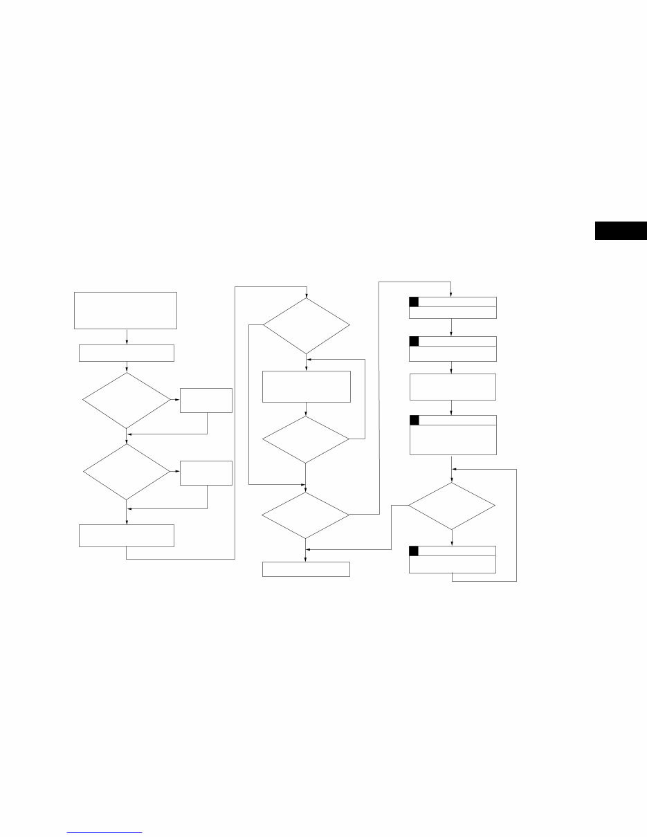
CHAPTER 1MAINTENANCE AND INSPECTION
A. Image Basic Adjustment Procedure
1–1
1
Clean the primary charging roller/transfer
charging roller.
• To clean the primary/transfer charging
roller, execute 'roller cleaning' under
adjustment/cleaning' in user mode.
Clean the separation static eliminatir.
Is the setting of
'EXPOSURE RECALIB''under
adjustment/cleaning'
in user mode a
medium value?
Is the setting of
service mode'*3*' the value
recorded in the label
attached to the front
door?
Make two to three copies in non AE
(copy density at 5).
Set it a medium
value.
NO
YES
YES
Enter the value
recorded in the
label.
NO
Is the white background
foggy?
YES
Excute shading auto correction.
Make two solid black copies
with the copyboard cover or
the feeder open
Service mode (*3*)
Set 'DENS-ADJ' to'5'
Is the white background
free of fogging?
Service Mode (*3*)
Set 'DENS-ADJ' to '5' or lower.
Are there vertical lines
(white,black)?
NO
YES
Clean the separation static
eliminator, dust-proofing glass,
mirrors (No.1,No.2,No.3), standrd
white plate,and lens.
Are the copies free
of vertical lines?
NO
YES
NO
END
Service mode (*4*)
Service mode (*4*)
Excute the following three items:
auto density correction PD
200PWM
60PWM
YES
NO
Downloaded from www.Manualslib.com manuals search engine
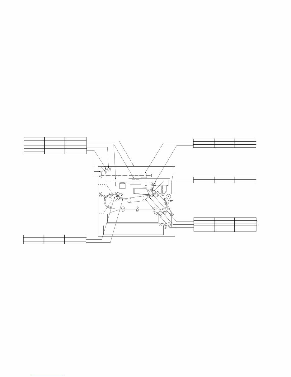
B. Points to Note for Scheduled Servicing
1–2
Part Tools/solvents Work/remarks
Copyboard glass
Original saize sensor
Scanning lamp
Reflecting plate
No.1 through No.3 mirrors
Alcohol
Blower brush
Lint-free paper
Blower brush
Cleaning
Cleaning
Dry wiping
As necessary, dry
wiping with lint-free paper
Part Tools/solvent Work/remarks
Part Tools/solvent Work/remarks
Part Tools/solvent Work/remarks
Lens
Dust-proofing glass
Blower brush
Blower brush
Cleaning
Cleaning
Developing roll Alcohol Cleaning
Cleaning
Cleaning
Cleaning
Optical assembly
Developing assembly
Transfer guide
Static eliminator
Feeding assembly
base/feeding belt
Moist cloth*
Special brush
Moist cloth*
Transfer/feeding assembly
*Make sure no droplet of water remains. Do not turn on
the power until the part is completely dry.
Part Tools/solvent Work/remarks
Separation claw
Inlet guide
Solvent
Solvent
Cleaning
Cleaning
Fixing assembly/delivery assembly
Downloaded from www.Manualslib.com manuals search engine
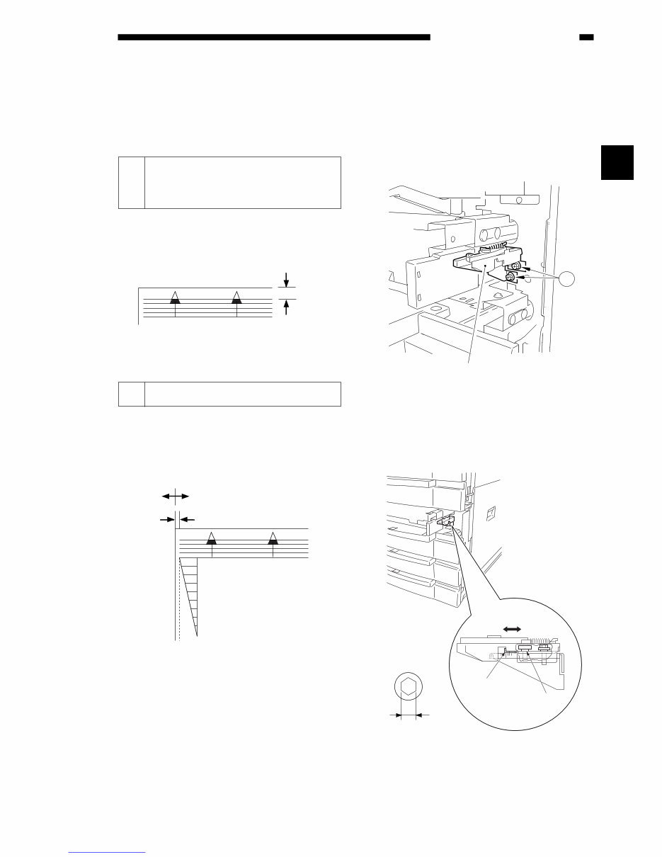
A. Mechanical
1 Image Leading Edge Margin
(REGIST; registration roller
ON timing)
Select ‘REGIST’ (4th screen) in service mode
(*3*; ADJUST) and adjust so that the image lead-
ing edge margin is 2.5 ±1.5 mm in Direct.
Figure 2-201
2 Left/Right Registration (front)
a. Pick-Up from the Cassette
Check to make sure that the margin on the
front side is 2.5 ±1.5 mm when paper is picked up
from each cassette.
Figure 2-202
Otherwise, perform the following:
1) Slide out the cassette to be adjusted.
2) Remove the two screws q, and remove the
horizontal registration adjustment assembly.
Figure 2-203
3) Loosen the hex screw, and slide the horizon-
tal registration plate toward the rear to adjust.
Figure 2-204
(rear) (front)
Horizontal
registration
plate
Hex screw
Hex screw diameter
4mm
1
Horizontal registration
adjustment assembly
(–) (+)
2.5±1.5mm
0
2
4
6
8
10
2.5±1.5mm
2–1
STANDARDS AND ADJUSTMENTS
CHAPTER 2 STANDARDS AND ADJUSTMENTS
2
Downloaded from www.Manualslib.com manuals search engine
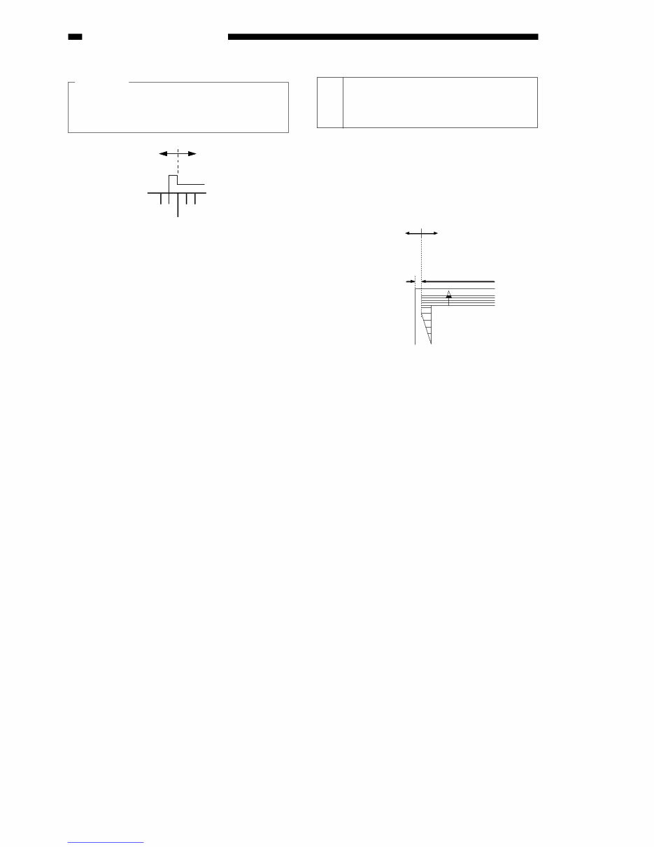
Caution:
To adjust, try so that the L-shaped notch on
the inside of the horizontal plate and the
appropriate scale notch match.
Figure 2-205
b. Pick-Up from the Multifeeder
Loosen the screw and move the tray position
so that it is 2.5 ±1.5 mm in Direct.
3 Left/Right Registration
(rear/front) on the 2nd Side of
Two-Sided/Overlay Copies
Check to make sure that the printing position
of the image on the second side of a two-
sided/overlay copy is 2.5 ±2.0 mm.
Figure 2-206
If the value is not as specified, select ‘RSID-
SENSHP’ (4th screen) in service mode (*3*;
ADJUST), and make adjustments.
• An increase by ‘23’ of ‘RSID-SENSHP’ will
shift the image print position to the rear by
1 mm.
A decrease by ‘23’, on the other hand, will
shift the position to the front by 1 mm.
2.5mm±2.0
Decrease the value of
'RSID-SENSHP'.
(A decrease by 23 causes
a change of 1 mm.)
Increase the value of
'RSID-SENSHP'.
(An increase by 23 causes
a change of 1 mm.)
2–2
STANDARDS AND ADJUSTMENTS
Downloaded from www.Manualslib.com manuals search engine
You're Reading a Preview
What's Included?
 Lifetime Access
Fast Download Speeds
Online & Offline Access
Access PDF Contents & Bookmarks
Full Search Facility
Print one or all pages of your manual
$31.99
CANON GP215/200 Service HandBOOK
Viewed 13 Times Today

What's Included?
Lifetime Access
Fast Download Speeds
Online & Offline Access
Access PDF Contents & Bookmarks
Full Search Facility
Print one or all pages of your manual
$31.99

Secure transaction
What's Included?
Lifetime Access
Fast Download Speeds
Online & Offline Access
Access PDF Contents & Bookmarks
Full Search Facility
Print one or all pages of your manual
Description
This is the full CANON Service Repair Manual for the GP215/200 model, with the part number FY8-23AM-000. The manual consists of (217) pages in PDF format and includes detailed pictures, diagrams, and step-by-step procedures. It is fully indexed and bookmarked by topic, allowing for quick searches within each chapter. The original Adobe document ensures high-quality printing and viewing. Users have the flexibility to print the entire manual or select specific pages. Additionally, zooming in on diagrams or pictures enables a detailed view of every part. This comprehensive manual is invaluable for professional mechanics and DIY enthusiasts alike.


