

carrier aquasnap chiller service manual
What's Included?
Fast Download Speeds
Online & Offline Access
Access PDF Contents & Bookmarks
Full Search Facility
Print one or all pages of your manual

Manufacturer reserves the right to discontinue, or change at any time, specifications or designs without notice and without incurring obligations.
Catalog No. 04-53300170-01 Printed in U.S.A. Form 30MP-4T Pg 1 8-17 Replaces: 30MP-3T
Controls, Start-Up, Operation,
Service, and Troubleshooting
CONTENTS
Page
SAFETY CONSIDERATIONS. . . . . . . . . . . . . . . . . . . . . 2,3
GENERAL . . . . . . . . . . . . . . . . . . . . . . . . . . . . . . . . . . . . . . 3-7
Conventions Used in this Manual . . . . . . . . . . . . . . . . 3
Basic Controls Usage . . . . . . . . . . . . . . . . . . . . . . . . . . . . 3
CONTROLS . . . . . . . . . . . . . . . . . . . . . . . . . . . . . . . . . . . 7-36
General . . . . . . . . . . . . . . . . . . . . . . . . . . . . . . . . . . . . . . . . . . 7
Main Base Board (MBB) . . . . . . . . . . . . . . . . . . . . . . . . . . 7
AUX Board (AUX) . . . . . . . . . . . . . . . . . . . . . . . . . . . . . . . . 7
Energy Management Module (EMM) . . . . . . . . . . . . . . 7
Current Sensor Board (CSB) . . . . . . . . . . . . . . . . . . . . . 7
Expansion Valve (EXV) Board . . . . . . . . . . . . . . . . . . . . 7
Enable/Off/Remote Control Switch . . . . . . . . . . . . . . . 7
Emergency On/Off Switch . . . . . . . . . . . . . . . . . . . . . . . . 7
Board Addresses . . . . . . . . . . . . . . . . . . . . . . . . . . . . . . . . 7
Control Module Communication . . . . . . . . . . . . . . . . . 7
Carrier Comfort Network
®
Interface . . . . . . . . . . . . . 13
Sensors . . . . . . . . . . . . . . . . . . . . . . . . . . . . . . . . . . . . . . . . . 15
• COOLER LEAVING FLUID SENSOR
• COOLER ENTERING FLUID SENSOR
• CONDENSER LEAVING FLUID SENSOR
• CONDENSER ENTERING FLUID SENSOR
• COMPRESSOR RETURN GAS
TEMPERATURE SENSOR
• OUTDOOR-AIR TEMPERATURE SENSOR
• DUAL LEAVING WATER TEMPERATURE SENSOR
• DISCHARGE TEMPERATURE THERMISTOR
• SPACE TEMPERATURE SENSOR
Energy Management Module . . . . . . . . . . . . . . . . . . . . 16
Loss-of-Cooler Flow Protection . . . . . . . . . . . . . . . . . 16
Condenser Flow Protection . . . . . . . . . . . . . . . . . . . . . 16
Thermostatic Expansion Valves (TXV) . . . . . . . . . . 16
Electronic Expansion Valves (EXV) . . . . . . . . . . . . . 17
Capacity Control . . . . . . . . . . . . . . . . . . . . . . . . . . . . . . . . 17
• MINUTES LEFT FOR START
• MINUTES OFF TIME
• CAPACITY CONTROL OVERRIDES
Time, Day, and Date . . . . . . . . . . . . . . . . . . . . . . . . . . . . . 20
Operation of Machine Based on Control Method. . 21
Cooling Set Point Select . . . . . . . . . . . . . . . . . . . . . . . . 25
Ice Mode . . . . . . . . . . . . . . . . . . . . . . . . . . . . . . . . . . . . . . . . 25
Cooler Pump Control . . . . . . . . . . . . . . . . . . . . . . . . . . . . 25
Alarm Routing. . . . . . . . . . . . . . . . . . . . . . . . . . . . . . . . . . . 25
Cooler Pump Sequence of Operation . . . . . . . . . . . 27
Condenser Pump/Condenser Fan Output
Control . . . . . . . . . . . . . . . . . . . . . . . . . . . . . . . . . . . . . . . . 27
Configuring and Operating Dual Chiller Control . . 27
Temperature Reset . . . . . . . . . . . . . . . . . . . . . . . . . . . . . . 31
Demand Limit . . . . . . . . . . . . . . . . . . . . . . . . . . . . . . . . . . . 34
• DEMAND LIMIT (2-Stage Switch Controlled)
• EXTERNALLY POWERED DEMAND LIMIT
(4 to 20 mA Controlled)
• DEMAND LIMIT (CCN Loadshed Controlled)
Cooling Set Point (4 to 20 mA) . . . . . . . . . . . . . . . . . . 34
Page
Digital Scroll Option . . . . . . . . . . . . . . . . . . . . . . . . . . . . 36
PRE-START-UP . . . . . . . . . . . . . . . . . . . . . . . . . . . . . . . 36,37
System Check. . . . . . . . . . . . . . . . . . . . . . . . . . . . . . . . . . . 36
START-UP AND OPERATION. . . . . . . . . . . . . . . . . 37-40
Actual Start-Up. . . . . . . . . . . . . . . . . . . . . . . . . . . . . . . . . . 38
Check Refrigerant Charge. . . . . . . . . . . . . . . . . . . . . . . 38
Check Compressor Oil Level . . . . . . . . . . . . . . . . . . . . 39
Adjust Oil Charge . . . . . . . . . . . . . . . . . . . . . . . . . . . . . . . 39
Operating Limitations . . . . . . . . . . . . . . . . . . . . . . . . . . . 40
• TEMPERATURES
• VOLTAGE — ALL UNITS
OPERATION SEQUENCE . . . . . . . . . . . . . . . . . . . . . . . . 40
SERVICE . . . . . . . . . . . . . . . . . . . . . . . . . . . . . . . . . . . . . 40-52
Service Test . . . . . . . . . . . . . . . . . . . . . . . . . . . . . . . . . . . . . 40
Charging . . . . . . . . . . . . . . . . . . . . . . . . . . . . . . . . . . . . . . . . 41
Electronic Components . . . . . . . . . . . . . . . . . . . . . . . . . 41
• CONTROL COMPONENTS
Electronic Expansion Valve (EXV) . . . . . . . . . . . . . . . 41
EXV Troubleshooting Procedure . . . . . . . . . . . . . . . . 42
Compressor Replacement . . . . . . . . . . . . . . . . . . . . . . 44
30MP Cooler and 30MPW Condenser . . . . . . . . . . . 44
• BRAZED-PLATE COOLER AND CONDENSER
HEAT EXCHANGER REPLACEMENT
• BRAZED-PLATE COOLER AND CONDENSER
HEAT EXCHANGER CLEANING
Water Treatment . . . . . . . . . . . . . . . . . . . . . . . . . . . . . . . . 45
Oil Charge . . . . . . . . . . . . . . . . . . . . . . . . . . . . . . . . . . . . . . 45
Check Refrigerant Feed Components . . . . . . . . . . . 45
• FILTER DRIER
• MOISTURE-LIQUID INDICATOR
• THERMOSTATIC EXPANSION VALVE (TXV)
• MINIMUM LOAD VALVE
• PRESSURE RELIEF DEVICES
Check Unit Safeties . . . . . . . . . . . . . . . . . . . . . . . . . . . . . 46
Thermistors . . . . . . . . . . . . . . . . . . . . . . . . . . . . . . . . . . . . . 46
Pressure Transducers . . . . . . . . . . . . . . . . . . . . . . . . . . 46
Chilled Water Flow Switch . . . . . . . . . . . . . . . . . . . . . . 47
Strainer . . . . . . . . . . . . . . . . . . . . . . . . . . . . . . . . . . . . . . . . . 52
Replacing Defective Modules . . . . . . . . . . . . . . . . . . . 52
MAINTENANCE . . . . . . . . . . . . . . . . . . . . . . . . . . . . . . . . . 52
Recommended Maintenance Schedule . . . . . . . . . . 52
TROUBLESHOOTING . . . . . . . . . . . . . . . . . . . . . . . . 52-71
Complete Unit Stoppage and Restart . . . . . . . . . . . . 52
• GENERAL POWER FAILURE
• UNIT ENABLE-OFF-REMOTE CONTROL SWITCH
IS OFF
• CHILLED FLUID PROOF-OF-FLOW SWITCH OPEN
• OPEN 24-V CONTROL CIRCUIT BREAKER(S)
• COOLING LOAD SATISFIED
• THERMISTOR FAILURE
• ENABLING AND DISABLING COMPRESSORS
• COMPRESSOR DISCHARGE CHECK VALVE
• LOW SATURATED SUCTION
• COMPRESSOR SAFETIES
AquaSnap
®
30MPA,MPW015-071
Liquid Chillers with Scroll Compressors
and ComfortLink Controls
2
CONTENTS (cont)
Page
Motor Overload Protection . . . . . . . . . . . . . . . . . . . . . . 54
• COPELAND COMPRESSOR MODELS WITH
ELECTRICAL CODE TF
• COPELAND COMPRESSOR MODELS WITH
ELECTRICAL CODE TW OR TE
• BITZER PROTECTION MODULE
• FIELD TROUBLESHOOTING SOLID-STATE
MOTOR PROTECTION MODULE
Alarms and Alerts . . . . . . . . . . . . . . . . . . . . . . . . . . . . . . . 59
APPENDIX A — LOCAL DISPLAY TABLES . . . 72-81
APPENDIX B — CCN TABLES . . . . . . . . . . . . . . . . 82-87
APPENDIX C — BACNET COMMUNICATION
OPTION . . . . . . . . . . . . . . . . . . . . . . . . . . . . . . . . . . . . 88-94
APPENDIX D — MAINTENANCE SUMMARY AND
LOG SHEETS . . . . . . . . . . . . . . . . . . . . . . . . . . . . . . 95,96
INDEX. . . . . . . . . . . . . . . . . . . . . . . . . . . . . . . . . . . . . . . . . . . . . . 97
START-UP CHECKLIST FOR 30MP LIQUID
CHILLER . . . . . . . . . . . . . . . . . . . . . . . . . . . . . CL-1 to CL-8
SAFETY CONSIDERATIONS
Installing, starting up, and servicing this equipment can be
hazardous due to system pressures, electrical components, and
equipment location (elevated structures, mechanical rooms,
etc.). Only trained, qualified installers and service mechanics
should install, start up, and service this equipment.
When working on this equipment, observe precautions in
the literature, and on tags, stickers, and labels attached to the
equipment, and any other safety precautions that apply. Follow
all safety codes. Wear safety glasses and work gloves. Use
care in handling, rigging, and setting this equipment, and in
handling all electrical components.
WARNING
Electrical shock can cause personal injury and death. Shut
off all power to this equipment during installation. There
may be more than one disconnect switch. Tag all discon-
nect locations to alert others not to restore power until work
is completed.
WARNING
DO NOT VENT refrigerant relief valves within a building.
Outlet from relief valves must be vented outdoors in
accordance with the latest edition of ANSI/ASHRAE
(American National Standards Institute/American Society
of Heating, Refrigerating and Air-Conditioning Engineers)
15 (Safety Code for Mechanical Refrigeration). The
accumulation of refrigerant in an enclosed space can
displace oxygen and cause asphyxiation. Provide adequate
ventilation in enclosed or low overhead areas. Inhalation of
high concentrations of vapor is harmful and may cause
heart irregularities, unconsciousness or death. Misuse can
be fatal. Vapor is heavier than air and reduces the amount
of oxygen available for breathing. Product causes eye and
skin irritation. Decomposition products are hazardous.
WARNING
DO NOT USE TORCH to remove any component. System
contains oil and refrigerant under pressure.
To remove a component, wear protective gloves and gog-
gles and proceed as follows:
a. Shut off electrical power to unit.
b. Recover refrigerant to relieve all pressure from sys-
tem using both high-pressure and low pressure ports.
c. Traces of vapor should be displaced with nitrogen
and the work area should be well ventilated. Refrig-
erant in contact with an open flame produces toxic
gases.
d. Cut component connection tubing with tubing cutter
and remove component from unit. Use a pan to catch
any oil that may come out of the lines and as a gage
for how much oil to add to the system.
e. Carefully unsweat remaining tubing stubs when nec-
essary. Oil can ignite when exposed to torch flame.
Failure to follow these procedures may result in personal
injury or death.
CAUTION
DO NOT re-use compressor oil or any oil that has been
exposed to the atmosphere. Dispose of oil per local codes
and regulations. DO NOT leave refrigerant system open to
air any longer than the actual time required to service the
equipment. Seal circuits being serviced and charge with
dry nitrogen to prevent oil contamination when timely
repairs cannot be completed. Failure to follow these proce-
dures may result in damage to equipment.
CAUTION
This unit uses a microprocessor-based electronic control
system. Do not use jumpers or other tools to short out
components, or to bypass or otherwise depart from recom-
mended procedures. Any short-to-ground of the control
board or accompanying wiring may destroy the electronic
modules or electrical components.
CAUTION
To prevent potential damage to heat exchanger, always run
fluid through heat exchanger when adding or removing
refrigerant charge. Use appropriate brine solutions in cooler
fluid loop to prevent the freezing of brazed plate heat
exchanger when the equipment is exposed to temperatures
below 32 F (0° C). Proof of flow switch is factory installed
on all models. Do NOT remove power from this chiller
during winter shutdown periods without taking precaution
to remove all water from heat exchanger and optional
hydronic system. Failure to properly protect the system
from freezing may constitute abuse and may result in loss
of warranty coverage.
CAUTION
Compressors require specific rotation. Monitor control
alarms during first compressor start-up for reverse rotation
protection. Damage to unit may result.
3
GENERAL
This publication contains Start-Up, Service, Controls, Oper-
ation, and Troubleshooting information for the 30MPW water-
cooled chillers and the 30MPA air-cooled chillers. For unit
sizes, see Table 1. These liquid chillers are equipped with Com-
fortLink controls and conventional thermostatic expansion
valves (TXVs, units 30MP015-045) or electronic expansion
valves (EXVs, units 30MP050-071). The 30MPA units and the
30MPW units with optional medium temperature brine are also
equipped with liquid line solenoid valves (LLSVs).
Table 1 — Unit Sizes
Conventions Used in This Manual — The follow-
ing conventions for discussing configuration points for the
local display (scrolling marquee or Navigator™ accessory)
will be used in this manual.
Point names will be written with the mode name first, then
any sub-modes, then the point name, each separated by an
arrow symbol (. Names will also be shown in bold
and italics. As an example, the Minimum Load Valve Select
Point, which is located in the Configuration mode, Option 1
sub-mode, would be written as ConfigurationOPT1
MLV.S.
This path name will show the user how to navigate through
the local display to reach the desired configuration. The user
would scroll through the modes and sub-modes using the
and keys. The arrow symbol in the path name
represents pressing to move into the next level of the
menu structure.
When a value is included as part of the path name, it will be
shown at the end of the path name after an equals sign. If the
value represents a configuration setting, an explanation will
be shown in parenthesis after the value. As an example,
ConfigurationOPT1MLV.S = YES (Minimum Load
Valve Select).
Pressing the and keys simultaneously
will scroll an expanded text description of the point name or
value across the display. The expanded description is shown in
the local display tables but will not be shown with the path
names in text.
The CCN (Carrier Comfort Network
®
) point names are also
referenced in the local display tables for users configuring the
unit with CCN software instead of the local display. The CCN
tables are located in Appendix B of the manual.
Basic Control Usage
SCROLLING MARQUEE DISPLAY — This device is the
keypad interface used for accessing unit information, reading
sensor values, and testing the unit. The scrolling marquee dis-
play is a 4-key, 4-character, 16-segment LED (light-emitting
diode) display. Eleven mode LEDs are located on the display
as well as an Alarm Status LED. See Table 2. For further details,
see Appendix A—Local Display Tables on page 72.
The scrolling marquee display module provides the user in-
terface to the ComfortLink control system. The display has up
and down arrow keys, an key, and an key.
These keys are used to navigate through the different levels of
the display structure. See Appendix A—Local Display Tables
on page 72. Press the key until the display is blank
to move through the top 11 mode levels indicated by LEDs on
the left side of the display.
Pressing the and keys simultaneously
will scroll a clear language text description across the display
indicating the full meaning of each display acronym. Clear lan-
guage descriptions will be displayed in the language of choice.
Pressing the and keys when the display is
blank (Mode LED level) will return the scrolling marquee dis-
play to its default menu of rotating display items, found under
Run StatusVIEW. In addition, the password will be disabled,
requiring that it be entered again before changes can be made
to password protected items. After a period of time with no key
activity, the scrolling marquee will display its default menu of
rotating display items found under Run StatusVIEW.
When a specific item is located, the display will flash show-
ing the operator, the item, the item value and then the item units
(if any). Press the key to stop the display at the item
value. Press the key again so that the item value
flashes. Use the arrow keys to change the value or state of an
item and press the key to accept it. Press the
key and the item, value, or units display will re-
sume. Repeat the process as required for other items.
NOTE: If a value has been forced, the lower right “.” will be
flashing.
See Table 3 and Appendix A for further details.
CAUTION
Refrigerant charge must be removed slowly to prevent loss
of compressor oil that could result in compressor failure.
CAUTION
Puron
®
refrigerant (R-410A) systems operate at higher
pressures than standard R-22 systems. Do not use R-22 ser-
vice equipment or components on Puron refrigerant equip-
ment. If service equipment is not rated for Puron
refrigerant, equipment damage or personal injury may
result.
CAUTION
This unit uses a microprocessor-based electronic control
system. Do not use jumpers or other tools to short out or
bypass components or otherwise depart from recom-
mended procedures. Any short-to-ground of the control
board or accompanying wiring may destroy the board or
electrical component.
UNIT MODEL NOMINAL TONS
30MPA,MPW015 15
30MPA,MPW020 20
30MPA,MPW030 30
30MPA,MPW040 40
30MPA,MPW045 45
30MPA,MPW050 50
30MPA,MPW055 55
30MPA,MPW060 60
30MPA,MPW065 65
30MPA,MPW071 71
ENTER
ESCAPE ENTER
ENTER ESCAPE
ESCAPE
ENTER ESCAPE
ENTER ESCAPE
ENTER
ENTER
ENTER
ESCAPE

4
Table 2 — Scrolling Marquee Display Menu Structure*
*Throughout this text, the location of items in the menu structure will be
described in the following format:
Item Expansion (Mode NameSub-mode NameITEM)
For example, using the language selection item:
Language Selection (ConfigurationDISPLANG)
MODE
RUN
STATUS
SERVICE
TEST
TEMPERATURES PRESSURES
SET
POINTS
INPUTS OUTPUTS CONFIGURATION
TIME
CLOCK
OPERATING
MODES
ALARMS
SUB-MODE
Auto
View of
Run Status
(VIEW)
Service
Test Mode
(TEST)
Unit Temperatures
(UNIT)
Pressures
Circuit A
(PRC.A)
Cooling
Setpoints
(COOL)
General
Inputs
(GEN.I)
General
Outputs
(GEN.O)
Display
Configuration
(DISP)
Time of
Day
(TIME)
Modes
(MODE)
Current
(CRNT)
Unit Run
Hour and
Start
(RUN)
Outputs
and Pumps
(OUTS)
Temperatures
Circuit A
(CIR.A)
Head
Pressure
Setpoint
(HEAD)
Circuit
Inputs
(CRCT)
Outputs
Circuit A
(CIR.A)
Unit
Configuration
(UNIT)
Month,
Date, Day,
and Year
(DATE)
Reset
Alarms
(RCRN)
Circuit and
Compressor
Run Hours
(HOUR)
Circuit A
Comp
Test
(CMPA)
Brine
Freeze
Setpoint
(FRZ)
4-20mA
Inputs
(4-20)
Outputs
Circuit A
EXV
(A.EXV)
Unit Options 1
Hardware
(OPT1)
Daylight
Savings
Time
(DST)
Alarm
History
(HIST)
Local
Holiday
Schedules
(HOL.L)
Compressor
Starts
(STRT)
Unit Options 2
Controls
(OPT2)
Preventive
Maintenance
(PM)
Circuit A EXV
Configuration
(EXV.A)
Schedule
Number
(SCH.N)
Software
Version
(VERS)
CCN Network
Configuration
(CCN)
Local
Occu-
pancy
Schedule
(SCH.L)
Reset Cool Temp
(RSET)
Schedule
Override
(OVR)
Set Point and
Ramp Load
(SLCT)
Service
Configuration
(SERV)
Broadcast
Configuration
(BCST)

5
Table 3 — Operating Modes
LEGEND
MODE
NO.
ITEM EXPANSION DESCRIPTION
01 CSM CONTROLLING CHILLER Chillervisor System Manager (CSM) is controlling the chiller.
02 WSM CONTROLLING CHILLER Water System Manager (WSM) is controlling the chiller.
03 MASTER/SLAVE CONTROL Dual Chiller control is enabled.
05
RAMP LOAD LIMITED Ramp load (pull-down) limiting in effect. In this mode, the rate at which leaving fluid temperature
is dropped is limited to a predetermined value to prevent compressor overloading. See Cooling
Ramp Loading (ConfigurationSLCTCRMP). The pull-down limit can be modified, if
desired, to any rate from 0.2° F to 2° F (0.1° to 1° C)/minute.
06
TIMED OVERRIDE IN EFFECT Timed override is in effect. This is a 1 to 4 hour temporary override of the programmed
schedule, forcing unit to Occupied mode. Override can be implemented with unit under
Local (Enable) or CCN (Carrier Comfort Network
®
) control. Override expires after each use.
07
LOW COOLER SUCTION TEMPA Circuit A cooler Freeze Protection mode. At least one compressor must be on, and the Sat-
urated Suction Temperature is not increasing greater than 1.1° F (0.6° C) in 10 seconds. If
the saturated suction temperature is less than the Brine Freeze Point (Set PointsFRZ
BR.FZ) minus 6° F (3.4° C) and less than the leaving fluid temperature minus 14° F
(7.8° C) for 2 minutes, a stage of capacity will be removed from the circuit. Or, If the satu-
rated suction temperature is less than the Brine Freeze Point minus 14° F (7.8° C), for
90 seconds, a stage of capacity will be removed from the circuit. The control will continue to
decrease capacity as long as either condition exists.
09
SLOW CHANGE OVERRIDE Slow change override is in effect. The leaving fluid temperature is close to and moving
towards the control point.
10 MINIMUM OFF TIME ACTIVE Chiller is being held off by Minutes Off Time (ConfigurationOPT2DELY).
13
DUAL SETPOINT Dual Set Point mode is in effect. Chiller controls to Cooling Set Point 1 (Set PointsCOOL
CSP.1) during occupied periods and Cooling Set Point 2 (Set PointsCOOLCSP.2)
during unoccupied periods.
14
TEMPERATURE RESET Temperature reset is in effect. In this mode, chiller is using temperature reset to adjust leav-
ing fluid set point upward and is currently controlling to the modified set point. The set point
can be modified based on return fluid, outdoor-air-temperature, space temperature, or 4 to
20 mA signal.
15
DEMAND LIMITED Demand limit is in effect. This indicates that the capacity of the chiller is being limited by
demand limit control option. Because of this limitation, the chiller may not be able to pro-
duce the desired leaving fluid temperature. Demand limit can be controlled by switch inputs
or a 4 to 20 mA signal.
16
COOLER FREEZE PROTECTION Cooler fluid temperatures are approaching the Freeze point (see Alarms and Alerts section
for definition). The chiller will be shut down when either fluid temperature falls below the
Freeze point.
17
LOW TEMPERATURE COOLING Chiller is in Cooling mode and the rate of change of the leaving fluid is negative and
decreasing faster than -0.5° F (-0.3° C) per minute. Error between leaving fluid and control
point exceeds fixed amount. Control will automatically unload the chiller if necessary.
18
HIGH TEMPERATURE COOLING Chiller is in Cooling mode and the rate of change of the leaving fluid is positive and increasing.
Error between leaving fluid and control point exceeds fixed amount. Control will automatically
load the chiller if necessary to better match the increasing load.
19
MAKING ICE Chiller is in an unoccupied mode and is using Cooling Set Point 3 (Set PointsCOOL
CSP.3) to make ice. The ice done input to the Energy Management Module (EMM) is open.
20
STORING ICE Chiller is in an unoccupied mode and is controlling to Cooling Set Point 2 (Set PointsCOOL
CSP.2). The ice done input to the Energy Management Module (EMM) is closed.
21
HIGH SCT CIRCUIT A Chiller is in a Cooling mode and the Saturated Condensing Temperature (SCT) is greater than
the calculated maximum limit. No additional stages of capacity will be added. Chiller capacity
may be reduced if SCT continues to rise to avoid high-pressure switch trips by reducing con-
densing temperature.
23
MINIMUM COMP ON TIME Cooling load may be satisfied, however control continues to operate compressor to ensure
proper oil return. May be an indication of oversized application, low fluid flow rate or low loop
volume.
24
PUMP OFF DELAY TIME Cooling load is satisfied, however cooler pump continues to run for the number of minutes set
by the configuration variable Cooler Pump Shutdown Delay (ConfigurationOPT1
PM.DY).
CSM — Chillervisor System Manager
SCT — Saturated Condensing Temperature
WSM — Water System Manager
6
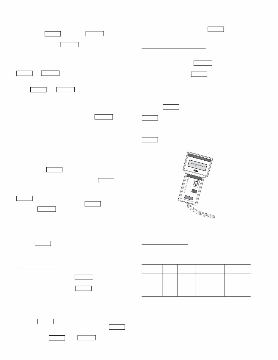
ACCESSORY NAVIGATOR™ DISPLAY MODULE —
The Navigator module provides a mobile user interface to the
ComfortLink control system. The display has up and down
arrow keys, an key, and an key. These
keys are used to navigate through the different levels of the dis-
play structure. Press the key until ‘Select a Menu
Item’ is displayed to move through the top 11 mode levels
indicated by LEDs on the left side of the display. See Fig. 1.
Once within a Mode or sub-mode, a “>” indicates the cur-
rently selected item on the display screen. Pressing the
and keys simultaneously will put the Nav-
igator module into expanded text mode where the full meaning
of all sub-modes, items and their values can be displayed. Press-
ing the and keys when the display says
‘Select Menu Item’ (Mode LED level) will return the Navigator
module to its default menu of rotating display items (those items
in Run StatusVIEW). In addition, the password will be dis-
abled, requiring that it be entered again before changes can be
made to password protected items. Press the key to
exit out of the expanded text mode.
NOTE: When the Language Selection (Configuration
DISPLANG), variable is changed, all appropriate display
expansions will immediately change to the new language. No
power-off or control reset is required when reconfiguring
languages.
When a specific item is located, the item name appears on the
left of the display, the value will appear near the middle of the
display and the units (if any) will appear on the far right of the
display. Press the key at a changeable item and the val-
ue will begin to flash. Use the up and down arrow keys to change
the value, and confirm the value by pressing the key.
Changing item values or testing outputs is accomplished in
the same manner. Locate and display the desired item. Press
so that the item value flashes. Use the arrow keys to
change the value or state and press the key to accept
it. Press the key to return to the next higher level of
structure. Repeat the process as required for other items.
Items in the Configuration and Service Test modes are pass-
word protected. The words Enter Password will be displayed
when required, with 1111 also being displayed. The default
password is 1111. Use the arrow keys to change the number
and press to enter the digit. Continue with the re-
maining digits of the password. The password can only be
changed through CCN operator interface software such as
ComfortWORKS, ComfortVIEW and Service Tool.
Adjusting the Contrast — The contrast of the display can be
adjusted to suit ambient conditions. To adjust the contrast of
the Navigator module, press the key until the dis-
play reads, “Select a menu item.” Using the arrow keys move
to the Configuration mode. Press to obtain access to
this mode. The display will read:
> TEST OFF
METR OFF
LANG ENGLISH
PAS.E ENBL
Pressing will cause the “OFF” to flash. Use the up
or down arrow to change “OFF” to “ON”. Pressing
will illuminate all LEDs and display all pixels in the view
screen. Pressing and simultaneously
allows the user to adjust the display contrast. Use the up or
down arrows to adjust the contrast. The screen’s contrast will
change with the adjustment. Press to accept the
change. The Navigator module will keep this setting as long as
it is plugged in to the LEN bus.
Adjusting the Backlight Brightness — The backlight of the
display can be adjusted to suit ambient conditions. The factory
default is set to the highest level. To adjust the backlight of the
Navigator module, press the key until the display
reads, “Select a menu item.” Using the arrow keys move to the
Configuration mode. Press to obtain access to this
mode. The display will read:
> TEST OFF
METR OFF
LANG ENGLISH
PAS.E ENBL
Pressing will cause the “OFF” to flash. Use the up
or down arrow keys to change “OFF” to “ON.” Pressing
will illuminate all LEDs and display all pixels in the
view screen. Pressing the up and down arrow keys simultane-
ously allows the user to adjust the display brightness. Use the
up or down arrow keys to adjust screen brightness. Press
to accept the change. The Navigator module will
keep this setting as long as it is plugged in to the LEN bus.
CHANGING THE DISPLAY LANGUAGE — The facto-
ry default language is English. Several other languages are
available, including Spanish, French, and Portugese.
Required Configurations — Table 4 shows the required con-
figurations for Language Selection.
Table 4 — LANG (Language Selection)
Required Configurations
NOTE: When the Language Selection (Configura-
tionDISPLANG) variable is changed, all appropriate dis-
play expansions will immediately change to the new language.
No power-off or control reset is required when reconfiguring
Language Selection.
CHANGING THE UNITS OF MEASURE — The factory
default unit of measure is English (for example, °F, ^F, psi).
The display can be changed to metric units (for example, °C,
^C, kPa).
ENTER ESCAPE
ESCAPE
ENTER ESCAPE
ENTER ESCAPE
ESCAPE
ENTER
ENTER
ENTER
ENTER
ESCAPE
ENTER
ESCAPE
ENTER
ENTER
ENTER
ENTER ESCAPE
SUB-
MODE
ITEM DISPLAY
ITEM
DESCRIPTION
COMMENT
DISP LANG X Language
Selection
Default: 0
Range: 0 to 3
0=English
1=Espanol
2=Francais
3=Portugese
ENTER
ESCAPE
ENTER
ENTER
ENTER
ENTER
Run Status
Service Test
Temperatures
Pressures
Setpoints
Inputs
Outputs
Configuration
Time Clock
Operating Modes
Alarms
ENTER
ESC
MODE
Alarm Status
ComfortLink
Fig. 1 — Accessory Navigator™ Display Module

7
Required Configurations — Table 5 shows the required con-
figurations for Metric Display.
Table 5 — METR (Metric Display)
Required Configurations
NOTE: When the Metric Display (Configura-
tionDISPMETR) variable is changed, all appropriate dis-
play expansions will immediately change to the new units of
measure. No power-off or control reset is required when recon-
figuring Metric Display.
CONFIGURATION AND SERVICE PASSWORD —
Items in the Configuration and Service Test modes are pass-
word protected. The words PASS and WORD will flash on the
scrolling marquee. Press for the digits 1111 to be
displayed. On the Navigator, press Enter Password and 1111
will be displayed. The default password is 1111. Use the arrow
keys to change each number if required and press to
accept the digit. Continue with the remaining digits of the pass-
word.
Changing Service Password — The password can only be
changed through CCN operator interface software such as
ComfortWORKS™, ComfortVIEW™, and Service Tool.
Caution should be exercised when changing the password.
Once changed, the only way to determine the password is
through one of these devices. To view or change the password,
use the CCN Variable PASSWORD found in Service Configu-
ration/Display.
CONTROLS
General — The 30MP liquid scroll chillers contain the
ComfortLink electronic control system that controls and moni-
tors all operations of the chiller.
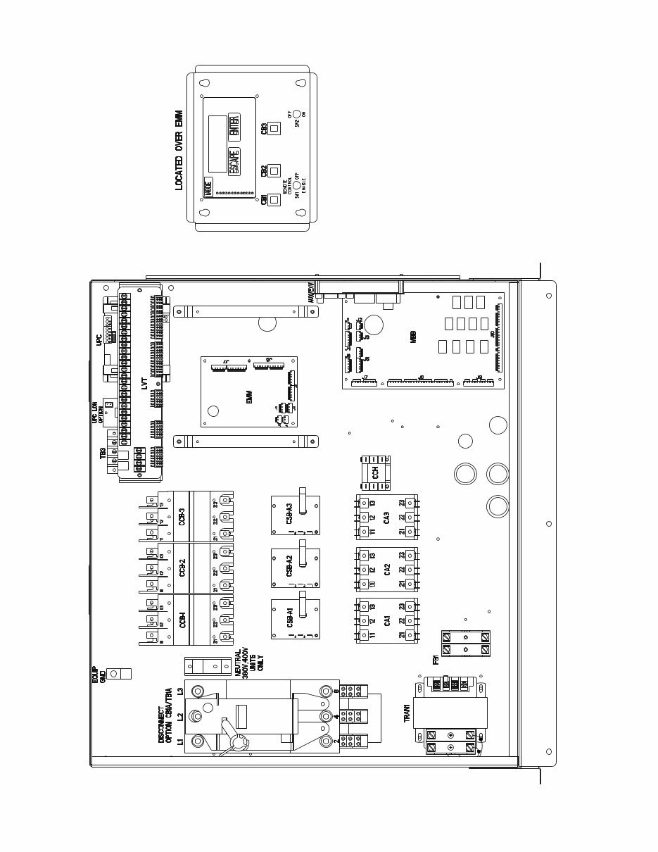
The control system is composed of several components as
listed in the sections below. See Fig. 2 for a typical control box
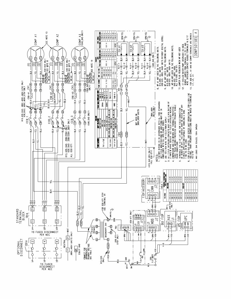
drawing. See Fig. 3 and 4 for power and control schematics.
See Table 6 for drawing designation.
Main Base Board (MBB) — See Fig. 5. The MBB is
the heart of the ComfortLink control system. It contains the
major portion of operating software and controls the operation
of the machine. The MBB continuously monitors input/output
channel information received from its inputs and from all other
modules. The MBB receives inputs from the discharge and
suction pressure transducers and thermistors. See Table 7. The
MBB also receives the feedback inputs from each compressor
current sensor board and other status switches. See Table 8.
The MBB also controls several outputs. Relay outputs con-
trolled by the MBB are shown in Table 9. Information is trans-
mitted between modules via a 3-wire communication bus or
LEN (Local Equipment Network). The CCN (Carrier Comfort
Network) bus is also supported. Connections to both LEN and
CCN buses are made at the LVT (low voltage terminal).
The Instance Jumper must be on “1.”
AUX Board (AUX) — The AUX board is used with the
digital scroll option (020-045 only). It provides additional in-
puts and outputs for digital scroll control. See Fig. 6.
Energy Management Module (EMM) — The EMM
module is available as a factory-installed option or as a field-
installed accessory. The EMM module receives 4 to 20 mA
inputs for the leaving fluid temperature reset, cooling set point
and demand limit functions. The EMM module also receives
the switch inputs for the field-installed 2-stage demand limit
and ice done functions. The EMM module communicates the
status of all inputs with the MBB, and the MBB adjusts the
control point, capacity limit, and other functions according to
the inputs received.
Current Sensor Board (CSB) — The CSB is used to
monitor the status of the compressors by measuring current and
providing an analog input to the main base board (MBB).
Expansion Valve (EXV) Board (050-071
only) — The EXV board communicates with the MBB and
directly controls the expansion valves to maintain the correct
compressor superheat.
Enable/Off/Remote Control Switch — The Enable/
Off/Remote Control switch is a 3-position switch used to
control the chiller. When switched to the Enable position the
chiller is under its own control. Move the switch to the Off
position to shut the chiller down. Move the switch to the
Remote Control position and a field-installed dry contact can
be used to start the chiller. The contacts must be capable of
handling a 24 vac, 50-mA load. In the Enable and Remote
Control (dry contacts closed) positions, the chiller is allowed to
operate and respond to the scheduling configuration, CCN
configuration and set point data. See Fig. 7.
Emergency On/Off Switch — The Emergency On/Off
switch should only be used when it is required to shut the
chiller off immediately. Power to the MBB, EMM, EXV,
AUX, and marquee display is interrupted when this switch is
off and all outputs from these modules will be turned off. See
Fig. 7.
Board Addresses — The main base board (MBB) has a
3-position instance jumper that must be set to 1. The EMM and
EXV board has 4-position DIP switches. All switches are set to
ON for all boards except the AUX board. The AUX board DIP
switch settings are shown on the wiring schematic.
Control Module Communication
RED LED — Proper operation of the control boards can be
visually checked by looking at the red status LEDs. During ini-
tial power-up the LED will signal a
1
/
2
-second blink 3 times,
followed by a pause. This indicates that the processor is boot-
ing. If this pattern repeats, it is an indication that the control
board is in a continuous reboot loop and the board should be re-
placed. When operating correctly, the red status LEDs should
be blinking in unison at a rate of once every 2 seconds. If the
red LEDs are not blinking in unison, verify that correct power
is being supplied to all modules. Be sure that the main control
is supplied with the current software. If necessary, reload cur-
rent software. If the problem still persists, replace the control
board. A red LED that is lit continuously or blinking at a rate of
once per second or faster indicates that the control board
should be replaced.
GREEN LED — The MBB has one green LED. The Local
Equipment Network (LEN) LED should always be blinking
whenever power is on. All other boards have a LEN LED
which should be blinking whenever power is on. Check LEN
connections for potential communication errors at the board J3
and/or J4 connectors. Communication between modules is
accomplished by a 3-wire sensor bus. These 3 wires run in
parallel from module to module. The J4 connector on the MBB
provides both power and communication directly to the
marquee display only.
YELLOW LED — The MBB has one yellow LED. The
Carrier Comfort Network (CCN) LED will blink during times
of network communication.
SUB-
MODE
ITEM DISPLAY
ITEM
DESCRIPTION
COMMENT
DISP METR OFF/ON Metric Display Default: OFF
OFF=English
ON=Metric
ENTER
ENTER
8
Table 6 — Component, Power, and Control Drawings
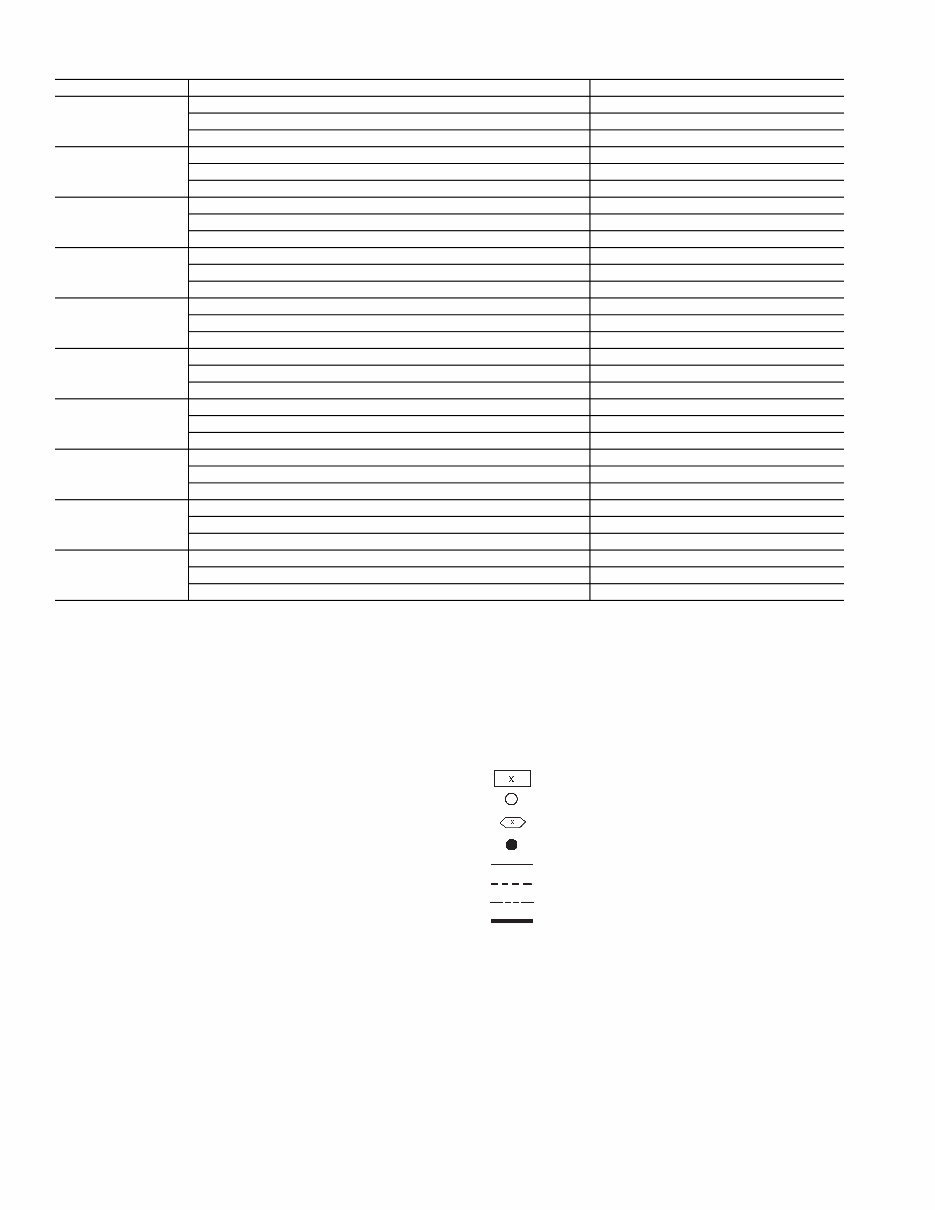
LEGEND FOR FIG. 3-5
30MPA,MPW UNIT DESCRIPTION LOCATION
015
Component Arrangement Fig. 2, page 9
Power Wiring Schematic Fig. 3, page 10
Control Wiring Schematic Fig. 4, page 11
020
Component Arrangement Fig. 2, page 9
Power Wiring Schematic Fig. 3, page 10
Control Wiring Schematic Fig. 4, page 11
030
Component Arrangement Fig. 2, page 9
Power Wiring Schematic Fig. 3, page 10
Control Wiring Schematic Fig. 4, page 11
040
Component Arrangement Fig. 2, page 9
Power Wiring Schematic Fig. 3, page 10
Control Wiring Schematic Fig. 4, page 11
045
Component Arrangement Fig. 2, page 9
Power Wiring Schematic Fig. 3, page 10
Control Wiring Schematic Fig. 4, page 11
050
Component Arrangement Fig. 2, page 9
Power Wiring Schematic Fig. 3, page 10
Control Wiring Schematic Fig. 4, page 11
055
Component Arrangement Fig. 2, page 9
Power Wiring Schematic Fig. 3, page 10
Control Wiring Schematic Fig. 4, page 11
060
Component Arrangement Fig. 2, page 9
Power Wiring Schematic Fig. 3, page 10
Control Wiring Schematic Fig. 4, page 11
065
Component Arrangement Fig. 2, page 9
Power Wiring Schematic Fig. 3, page 10
Control Wiring Schematic Fig. 4, page 11
071
Component Arrangement Fig. 2, page 9
Power Wiring Schematic Fig. 3, page 10
Control Wiring Schematic Fig. 4, page 11
ALMR — Alarm Relay
AUX — Auxilliary
C — Contactor, Compressor
CB — Circuit Breaker
CCB — Compressor Circuit Breaker
CCH — Crankcase Heater Relay
CNFS — Condenser Water Flow Switch
CNPI — Condenser Pump Interlock
COMP — Compressor
CR — Control Relay
CSB — Current Sensing Board
CWFS — Chilled Water Flow Switch
DGS — Digital Scroll Compressor
DPT — Discharge Pressure Transducer
DTT — Discharge Temperature Thermistor
DUS — Digital Unloader Solenoid
EMM — Energy Management
EXV — Expansion Valve Board/Electronic Expansion Valve
FB — Fuse Block
FIOP — Factory-Installed Option
FU — Fuse
GND — Ground
HPS — High-Pressure Switch
LLSV — Liquid Line Solenoid Valve
LON — Local Operating Network
LVT — Low Voltage Terminal
LWT — Leaving Water Temperature
MBB — Main Base Board
MLV — Minimum Load Valve
MP — Modular Motor Protection
MTT — Motor Temperature Thermistor
NEC — National Electrical Code
OAT — Outdoor-Air Thermistor
OPT — Option
PL — Plug
RGT — Return Gas Temperature
SPT — Suction Pressure Transducer
SW — Switch
TB — Terminal Block
TRAN — Transformer
UPC — Unitary Protocol Converter
Terminal Block
Terminal (Unmarked)
Terminal (Marked)
Splice
Factory Wiring
Field Wiring
Accessory or Option Wiring
To indicate common potential only; not to represent
wiring.
9
a30-5984
Fig. 2 — Typical Control Box — 30MP015-071 Units
10
Fig. 3 — Typical Power Wiring Schematic — 30MP015-071 Units
You're Reading a Preview
What's Included?
Fast Download Speeds
Online & Offline Access
Access PDF Contents & Bookmarks
Full Search Facility
Print one or all pages of your manual
$31.99
Viewed 56 Times Today


Secure transaction
What's Included?
Fast Download Speeds
Online & Offline Access
Access PDF Contents & Bookmarks
Full Search Facility
Print one or all pages of your manual
$31.99
Get the comprehensive AquaSnap Air-Cooled Chillers manual for the 30RA010-055 model. This manual covers everything from controls and start-up to operation, service, and troubleshooting. Whether you're a professional mechanic or a DIY enthusiast, this manual is an invaluable resource for maintaining and repairing your chiller.


