Zetor 4712/4718/5711/5718/5745/5748/6711/6718/6745/6748 Tractors OEM Service & Repair Manual
What's Included?
Lifetime Access
Fast Download Speeds
Online & Offline Access
Access PDF Contents & Bookmarks
Full Search Facility
Print one or all pages of your manual
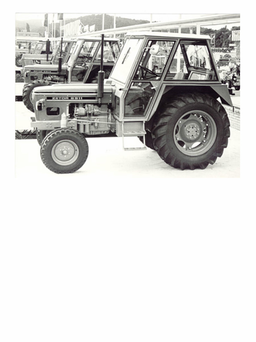
ZETOR WORKSHOP MANUAL Assembly, Dismantling and Repairs of ZETOR 4712, 4718, 5711, 5718, 5745, 5748, 6711, 6718, 6745, 6748,
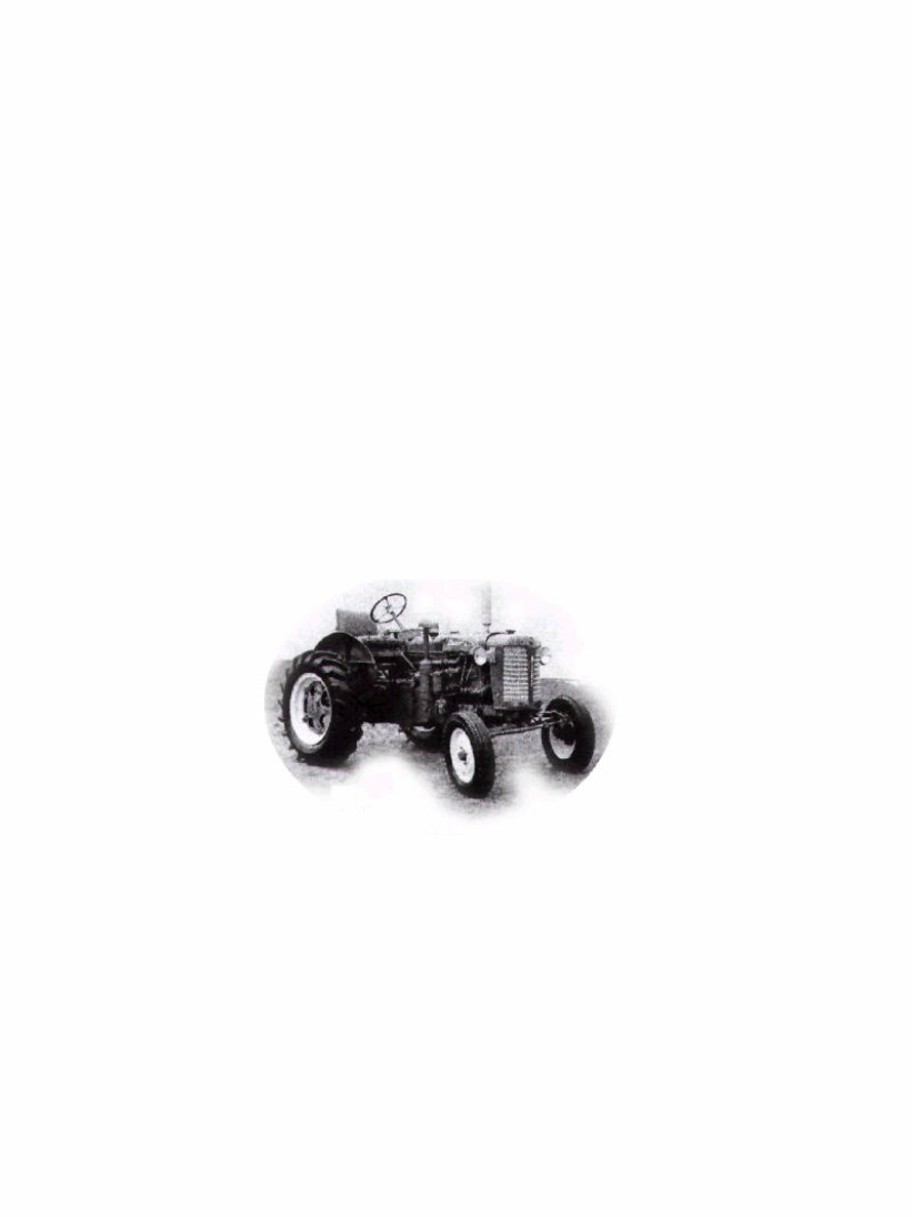
For more than 50 years, Zetor have been producing quality-built, top-value tractors for the agricultural industry around the world. The manufacture of Zetor Tractors started well before the 2 nd. World War in the city of Brno in the province of Moravia which was lately part of Czechoslovakia and is more recently part of the Czech Republic. The first Distributor to import Zetor Tractors into the UK and Ireland was in 1947. Zetor was just about the only full Diesel Tractor to be sold in the UK and Ireland as other diesel tractors used petrol to start their engines. Early Zetor tractors had no starter motor and no hydraulic lift some of these tractors can still be seen in tractor museums. These models were very famous for their high road speed where speeds in excess of 40 m.p.h. were spoken about. The major turning point for Zetor occurred in 1962 when the UR1 Range of tractors were launched on the world market. This range of tractor was technically equal to any competitor in the world market and by 1978/79 Zetor was challenging the leading manufacturers Ford and Massey Ferguson for top place in the Irish Tractor Market. Another major occurrence happened in 1970 when UR11 Crystal Tractors were introduced to the market. These tractors were ahead of their time in design and technology and were the favoured tractor of most contractors and owners of large farms. While the UR1 range of tractor was extensively modified and changed in order to keep up with modern tractor technology, over the years the Crystal tractor remained unchanged for almost 30 years. Gradually its popularity declined due to the advance technology of it's competitors. The reason for this decline was the transfer of the manufacturing facility for the Crystal range from its parent factory in Brno to a factory in Northern Slovakia where they had no research and development department. This move was political where employment was moved from high density employment areas to employment black spots throughout Eastern Europe. Luckly a replacement for the Crystal range of tractors finally arrived in the mid 90's which was called the Forterra. The Forterra range brought Zetor back up to the cutting edge of modern designand and technology in agricultural tractors. Replacing the Super UR1 range we now have available the Proxima Zetor Range of tractor. This range gives the tractor purchaser in the 60 - 90 horse power range a very high level of technology and performance. Every Zetor tractor was covered by a one year warranty guarantee, no gimmicks, no fine print. Every Zetor was backed by its commitment to the customers for service after the sale. Down through the years the key note of Zetor's success has been tough, reliable tractors at an affordable price offering many years of trouble free service to their users coupled with an excellent re-sale value.
Zetor Tractor Factory Company was established in 1946 in Brno, Czech Republic, and over a 50-year span has become one of the largest tractor manufacturers in Europe. In 1998 Zetor completed production and sales of the first 1 million of the firm's Range 1 tractor units. Today Zetor tractors and implements are at work in more than 100 countries around the world. The continuing success and growth of the company is based on its traditional research and development resources. Zetor designs and produces most of its tractor components, including the engines, which are among the most fuel efficient in the industry. Throughout the past 58 years, Zetor R&D pioneered various new concepts. In 1960, the organization produced one of the first hitch-hydraulic systems (Zetormatic), with full- position, draft and mixed control capability. Later it was the first tractor company to manufacture a fully integrated safety cab with insulated, rubber-mounted suspension - an idea later adopted by all other manufactures. Again on current models, (even for the smallest Zetor, at 43 hp), Zetor pioneered a flat, vibration insulated, rubber mounted platform (operator's station) - a feature not found on any competitive model in this horse power category.
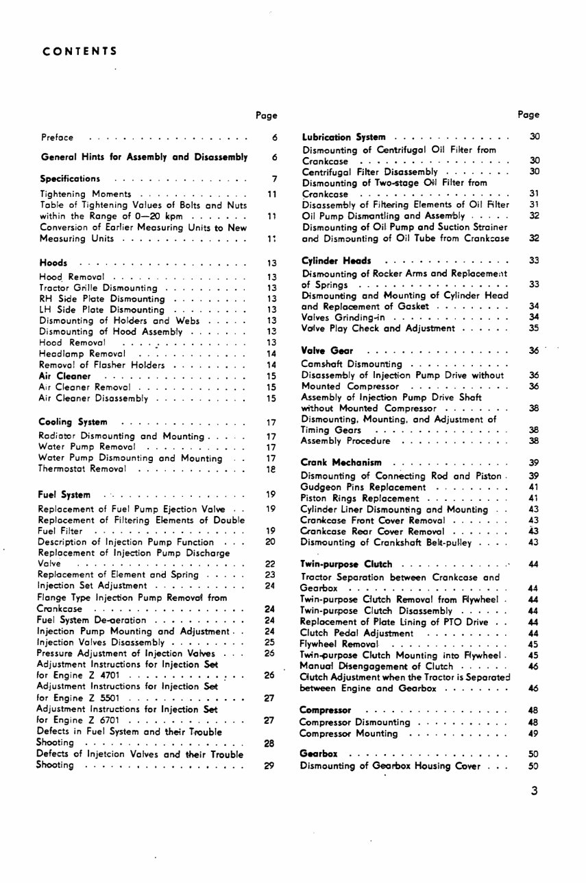
CONTENTS Preface General Hints for Assembly and Disassembly Specifications Tightening Moments ............ . Tobie of Tightening Values of Bolts end Nuts within the Range of 0-20 kpm ...... . Conversion of Earlier Meesuring Units to New Meesuring Units Hoods Hood. Removal . Trector Grille Dismounting RH Side Plate Dismounting LH Side Plate Dismounting Dismounting of Holders end Webs Dismounting of Hood Assemb"ly Hood Remove! ..... Heodlemp Removal Removal of Flesher Holders Air Cleaner . . . . . . Air Cleener Removal .. Air Cleaner Disassembly Cooling System Rediator Dismounting and Mounting . Water Pump Removal Water Pump Dismounting end Mounting Thermostet Removal .......... • Fuel System Repkicement of Fuel Pump Ejection Valve .. Replacement of Filtering Elements of Double Fuel Filter . . . . . . . . . . • . . . . . . Description of Injection Pump Function Replacement of Injection Pump Discharge Velve .............. . Replacement of Element end Spring . . . Injection Set Adjustment . . . . . . . . . Flenge Type Injection Pump Remove~ from Cl"Clnkcese .... · . • . • · · · • · · · Fuel System De-aeretion . . • . . . • . . Injection Pump Mounting end Adjustment . Injection Velves Disessem·bly ..•... Pressure Adjustment of Injection Volves Adjustment Instructions for Injection Set for Engine Z 4701 ....... •.•• Adjustment Instructions for Injection Set for Engine Z 5501 . . . • . • . . .•• Adjustment Instructions for Injection Set for Engine Z 6701 ....... •... Defects in Fuel System end their Trouble Shooting .............. •.• Defects of lnjetcion Velves and t-heir Trouble Shooting ...... •.•.•.•.•.•.. Page 6 6 7 ,, 11 13 13 13 13 13 13 13 13 14 14 15 15 15 17 17 17 17 1e 19 19 19 20 22 23 24 24 24 24 25 26 26 27 27 28 Lubrication System . . • . . - · . . . . . . Dismounting of Centrifugal Oil Filter from C·rankcase • . • . • · · · · · · · · · · • Centrifugal Filter Disassembly . . . . . . • Dismounting of Two-stage Oi:I Filter from Crankcase .. · · • · • · · · · · · · · · · Oisessembly of Filtering Elements of Oil Filter Oil Pump DjsmantUng and Assem'bly . . . . . Dismounting of Oil Pump and Suction Stroin~r and Dismo-unting of Oil Tube from Crankcase Cylinder Heads • . • · • · • · · . . . • . • Dismounting of Rocker Arms and Rep'loceme;1t of Springs .... • · • · · · · . · ... · . Dismounting and Mounting of Cylinder Head and Replacement of Gasket . . . Valves Grinding..jn . . . . • . . . VCJ1lve Ploy Check and Adjustment Valve Gear Cemshoft Dismounting . . • . . . Disassembly of Injection Pum.p Drive without Mounted Compressor ..• ...... Assembly of Injection Pum.p Drive Shaft without Mounted Compressor . . . . . Dismounting, Mounting, and Adjustment of Timing Gears Assembly Procedure Crank Mechanism Dismounting of Connecting Rod and Piston . Gudgeon Pins Replacement . . . . . . • Piston Rings Replacement . . • . . . . . Cylinder Liner Dismounting and Mounting Cron«cose Front Cover Removal . . . Crankcase Rear Cover Removal ..• Dismounting of Crankshaft Beht-pul·ley Twin-purpose Clutch ... Tractor Separation between Crenkcese and Gearbox .... •...• ......... Twin-purpose Clutch Removel from F4ywheel Twin-pur.pose Clutch Disassembly . . . . Replacement of Plate Lining of PTO Drive Clutc·h Pedal Adjustment . . • . . . Flywheel Removal .......... · . Tw;n"i)urpose Clutch Mounting into Flywheel . Manua·I Ol'Sengagement of Clutch . . . . . . Cfutch Adjustment when the Tractor is Separated between Engine and Gearbox Compressor . • . . . . Compressor Dismounting Compressor Mounting Gearbox Dismounting of Gearbox Housing Cover Page 30 30 30 31 31 32 32 33 33 34 34 35 36 36 36 38 38 38 39 39 41 41 43 43 43 43 44 44 44 44 44 44 45 45 46 48 48 49 50 50 3
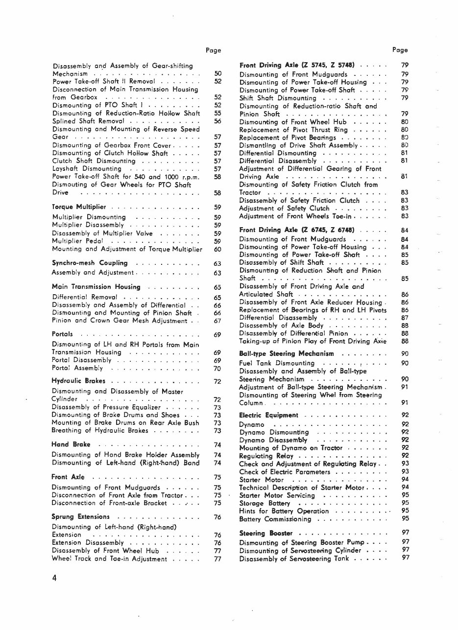
Disassembly an.d Assembly of Gear-shifting Mechanism ... ..... .. . .... . . Power Take-off Shaft II Removal .. Disconnection of Mein Transmission Housing from Gearbox . .. . ........... . Dismounting of PTO Shaft I . . . . . . . . . Dismounting of Reduction-Ratio HoJ.low Shaft Splined Shoft Removal ........... . Dismounting ond Mounting of Reverse Speed Geer .... .... . .. . .... . Dismounting of Gearbox Front Cover. Dismounting of Glutch Ho•low Shaft Clutch Shaft Dismounting ..... . Loyshaft Dismounting ..... . . . Power Take-off Shaft for 540 and 1000 r.p.m. Dismouting of Geer Wheels for PTO Shaft Drive ..... Torque Multiplier . .. Multiplier Dismounting Multiplier Disassembly Disassembly of Multiplier Valve Multiplier Pedal .. .... • . Mounting end Adjustment of Torque Multiplier Synchro-mesh Coupling Assembly on<i Adjustment . Main Transmission Housing Differential Removal . . . . Disassembly end Assembly of Differential Dismounting and Mounting of Pinion Shof.t Pinion end Crown Geer Mesh Adjustment Portals Dismounting of LH end RH Portals from Main Transmission Housing Portal Disossem'bly Portal Assembly Hydraulic Brakes Dismounting and Disassembly of Moster Cylinder ........... . Disassembly of Pressure Equalizer . .. . Dismounting of Broke Drums and Shoes . Mounting of Broke Drums on Rear Axle Bush Breathing of Hydraulic Brakes Hand Brake Dismounting of Hand Broke Holder Assembly Dismounting of Lef.t-hond (Right-'hond) Band Front Axle Dismounting of Front Mudguards . . • . Disconnect-ion of Front Axle from Tractor. Disconnection of Front-axle Brocket •· Sprung Exten5ions . . . . . . . . . Dismounting of Left-hond (Right-hand) Extension ... . .. ..... . Extension Disassembly . . • . . .. Disassembly of Front Wheel Hub . Wheel Track ond Toe-in Adjustment 4 Page 50 52 52 52 55 56 57 57 57 57 57 58 58 59 59 59 59 59 60 63 63 65 65 66 66 67 69 69 69 70 72 72 73 73 73 73 74 74 74 75 75 75 75 76 76 76 n n Front Driwing Axle (Z 5745, Z 5748) Dismounting of Front Mudguards •. Dismounti ng of Power Toke-off Housing Dismounting of Power Toke-off Shaft .. Shift Shaft Dismounting . . . . Dismounting of Reduction-ratio Shaft and Pinion Shaft . . . . • . . . Dismoull1:ing of Front Wheel Hub Replocement of Pivot Thrust Ring Replacement of Pivot Bearings . . Dismantling of Drive Shaft Assembly . Differential Dismounting . . • . . . • Differential Disossem·bly . . . . . . Adjustment of Differential Geari ng of Front Driving Axle . . . . . . . . . . • . • .•. Dismounting of Safety Friction Clutch from T-roctor . . . . . . • . . . • .•. Disassembly of Safety Friction Clutch Adjustment of Safety Clutch . . . . Adjustment of Front Wheetls Toe.in • Front Driwing Axle (Z 6745, Z 6748) Dismounting of Front Mudguards Dismounting of Power Toke-off Housing Dismounting of Power Toke-off Shaft Disassembly of Shift Shaft • . . . . . • Dismounting of Reduction Shaft and Pinion Shaft .. .. .. · . •... · . · · · · Disassembly of Front Driving Axle and Articulated Shaft . . . . . • . • ...• Disassembly of Front Axle Reducer Housing . Replacement of Beorings of RH and LH Pivots Differenti al Disassembly Disassembly of Axle Body . . . . . . . . Disossembl'f of Differentia l Pinion . . . . • . Taking-up of Pinion Pl<1y of Front Driving Axie Ball-type Steering Mechanism Fuel Tonk Dismounting Disassembly and Assem'bly of Boll-type Steering Mechanism ..• . • ..... Adjustment of Ball-ty.pe Steering Mechan;sm . Dismounting of Steer-ing Whel from Steering Column . • .• Electric Equipment Dynamo ... . · · Dynamo Dismounting Dynamo Disossemb1'f Moull1:ing of Dynamo on Tractor ReguJ.cting R~oy • . • . • . • . Check and Adjustment of Regukiting Relay . Check of Electric Parameters . . • . • Starter Motor . . . . • . • . . . . . Technical Description of Starter Motor • Starter Motor Serv- icing Storage Battery • . • . • . Hints for Battery Operation Battery Commissioning Steering Booster • . Dism<>unting of Steering Booster Pump • Dismounting of SeNOsteering Cylinder Disassembly of Servosteering Tonk •. • Page 79 79 79 19 79 79 80 80 8'.> 80 81 81 81 83 83 83 83 84 84 84 85 85 85 86 86 86 87 BB 88 88 90 90 90 91 91 92 92 92 92 92 92 93 93 94 94 95 95 95 95 97 97 97 97
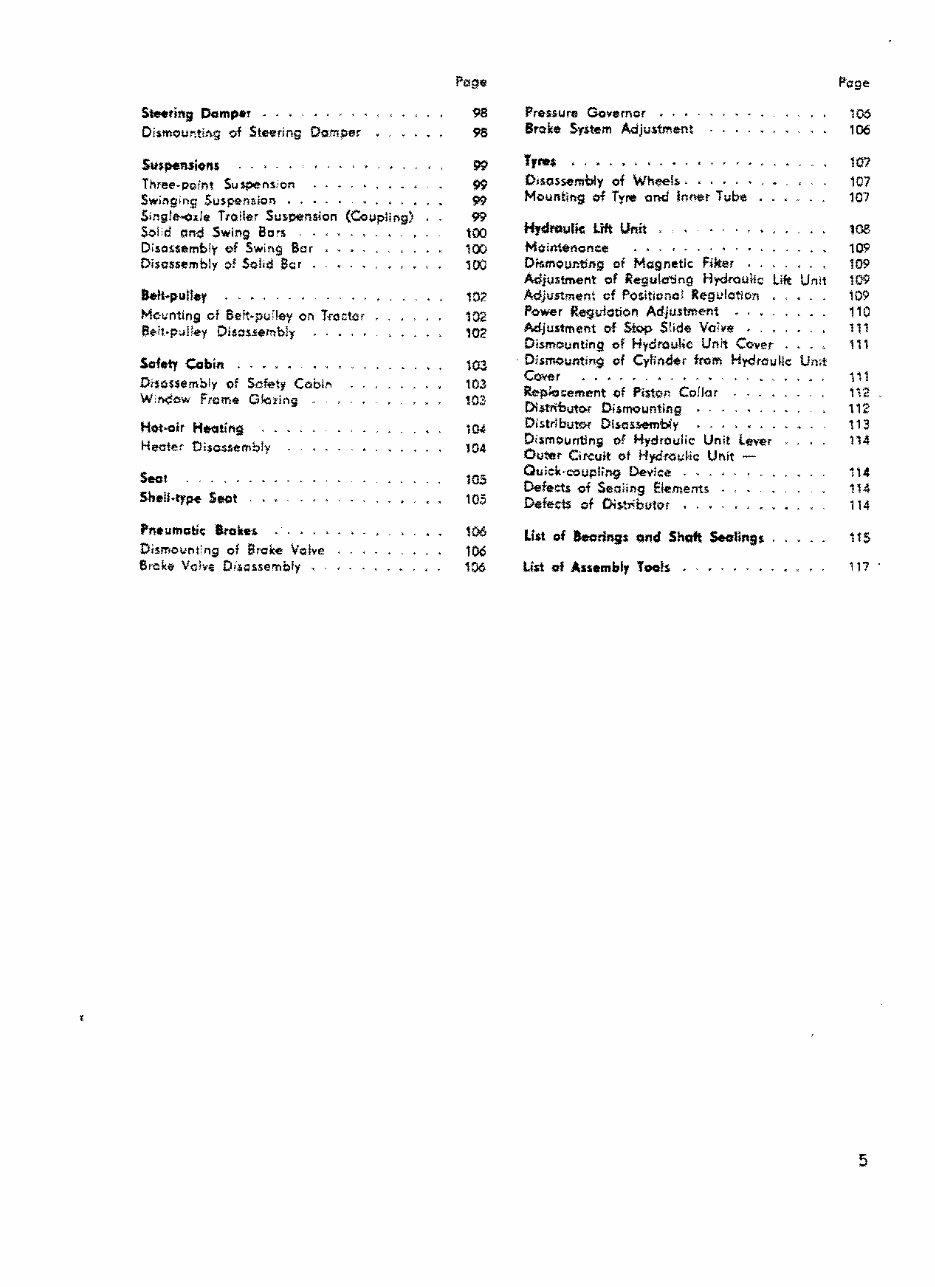
s-.ring Damper . ' ' OismQuntittg Qt Steering Dompe~ Suspe.Mions Three.point Suspens.·on SwL'\gin9 Suspe-naion . . , Singl&<ixl1;1 Troile:r Suspension {Coupling) Sol cl ciru;I Swif'lg Bc•s - . , .. - . , _ , Disoi;semb!y of Swing Ber Piscssembly of Solid $Qr a.tt~puller M<:-i;nttn9 cf Seit·pu'.!ey on lrocter e~it-p;.iHey Disassembly Safety Cabin . Di1ossembly of Sc~ty Cob!,., W.r.;;Jow Frome O~;ing Hot-air HlfQting Heat~t tliscsl\emb!y Seat Shell.type. Seot Pneumciti< Brakes Dismovf'lt'ng of Broke \lo!Ye Sn::ke- Vo!vE Oi,oosse'l"lb!y , .. •• 99 99 99 99 too 100 100 102 102 102 tro 103 103 "'" 104 103 105 too 106 106 Pressure Governor •. • Brol:e System Adjusiment f'l'age 106 106 ,,,.. • ' ' . . 107 01sossembly of Whee!,o. 107 Mountll'lg of TyJ'\t -end Inner Tube 107 Hy-droulk Lift Unit . 108 Mo-ifrt1tnonee 109 Ors.mounting of Magnetic Fiker 109 Adjustment of Regu!(f'jng Hydroullc Lift Unit 109 Adjustment cf Positk1ntJ! Regulotlon 109 Power Regu!otion Adjustment • , , 110 Adjustment of Stop Slid$ va;vtt • . 111 Dismounting of HydrouH<: Unit Cover . 111 - Dismounting of Cylif'ld$r from Hydrou~e Un;t ~r . . . . . 111 Replocernent -of Piston Co!Jor 1i'2 DiJCtributQ.r Dismounting • 112 Distributor OiJCasl'temtiy , • . 113 Di$mOuntln5 of Hydroulic Unit lever 114 Outoer Circuit of Hydt\'.H.;Hc Unft Oulek·coupltng Device tt4 Defects of Sealing E!«ments . 114 Defe.rn of Oi$oti'buto; • 114 Ll•t of hcrings ond Shaft Seolings 115 U$i of Assembly Tools . 117 5
PREFACE This workshop monuol is intended for maki ng ac- quainted the users of tractors, repair mechanics and emp loyees of authorized repa ir worU+lop with o deta il ed explanation of the desi gn, techn ical ma in· tenonce ond repairs of tractors Zetor 4712, 4718, 5711. 5718, 5745, 57.48, 6711. 6718, 6745, 6748. It contains o systematic summary of instructions and operations for ind i vidual jobs . The use of this ma- nual assumes o thorough know1edge of the atten- dance of troct:>rs, spore ports ond components. Its is for this reoson that on Operation Manua l and o list of Spore Ports were issued for tractors Zetor 4712-6748. Dismantling and 'l'epoirs are always to be done with the he lp of a special assembly set of tools to prevent any cont i ngent further damage to the tractor. There- fore, the individual instructions state the tools of the spec ia l assembly set by means of Which the neces- GENERAL HINTS FOR ASSEMBLY ANO OISASSEMBL Y 1. Work on ly with su itab le ond undamaged too !s. Use to maximum socket ond box wrenches. 2. Ant i frict ion bearings to be mounted in tractors ore to be extracted from the origino'I poclcings only immediotely prior to assembly. Remove pre- servation grease by washing the bearing in kero- sene. After dean i ng , check the bearing for pro· per funct ion and lubricate it with oil. 3. The shaft sea li ngs Gufero ore to be given greot core du ri ng the ir mount i ng. Prior to pressing them in, check the sea ling surface or spri ng for damage, dip the Gufero sea li ng in pure oil or smear its surfaces with o rog soaked in oil. 4. Pressed-in or hot mounted components ore to be dismantled on ly under a press with the use of o suitable mandre l. Contact surfaces of com- ponents to be pressed or hot driven together are always to be oi '1ed proper1y. 5. Make sure that al l dismant ' led components, In case of their reossem'bly, were mounted in the ir orig i nal p laces. lt is of special Importance to 6 sory dismantling and/ or assembly con be ca rri ed out. We beg to recommend to stick to the disassembly ond assembl y P'QCedures, because they represent experience results of the meC'honics and techn icians of the production pl ant and were acquired in long- -term practice. Getting perfectly acquainted with this manual and proceeding during repa i rs according to the inst>ructions stated therein, you wi · f'I preclude any . contingent damage to the tractprs which might be caused by insufficient professional knowledge. Not ifi cation I Th is manua l Is not bindi ng os for as design features and equipment of the tractors supp1i ed are concern- ed. Tne effort of the manufacturers is to perfection their products and, therefore, they reserve t'he right to make changes in illustrations and texts so as to lceep abreast with the further development of the ir products. The bas .is of tile Workmop Monvo1 is fonned by the tractors Zetor 5711 end Zetor 6711. stick to this rule in cose of repeated use of bear- in g needles and ro11ers. 6. Prior to assembly. c1eon o ff components properly ond smear with 'Oto!, grease, etc . a ll their contact parts and especia ll y the ir friction surfaces. 7. Mount on ly sue'h worn components whose wear did not still exceed tile limit of the required re- liability and operation safety and whose discord- i ng would not st lll be economical 8. Hoving used oreomers, grinding paste or another means for the finisih of components, make sure to remove any chips with pressure air and petro l. 9. Poper and rubber seolings. various lock wires. sheets and split pins though seemi ng after dis- mont li ng apporontly undomoged ore always dur- ing the assembly to be replaced by new ones. Dry paper gaskets ore to be soaked in wate r prior to mount i ng. 10. During the mounti ng of needles into bearings. make use for sticki ng them in place of vaselines of such kinds having the me1ting point of about f:JJ• c. 11. Tools for assembly and d1s asemb ' ly are stated direct in the indMdual chapters and in every figure are given toheir order num0ers.
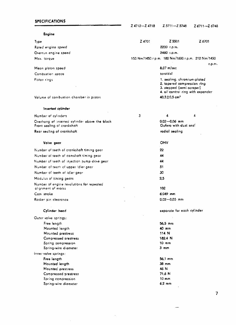
SP~CIFICATIONS Engine Type Roted er,g;nt< speed OverTwn ef'lgine speed Mc:t. torque Meon pis,ton speed ComQust;or: spoce: F:s1on r:ngs Volume of comb.istion chomber in piston Inserted cylinder Numbet o' oylinde~s Overhong of :nsertec <'Y 1 '!'lde1 obo¥e the block Front sealing of cronkshoft Rear S&O!ing of cmnkshcit Volve geor N;imbe• o• t~tk ol cronkshoft tim:ng geor Nu'f\bet of 1eeth of comshoft 1:m 0 n9 geo; Number cf :eeth of nject1on oul'llp drive geor Nvmbe: cf teet"1 vf upper -·dler gecr Number of teeth of id!e' geor ModJlu~ o• timing gears Num~r of engire tevotutions for repealed ol g'H'!'ifnt o 1 marks Com stroke Roeker pin e!eorcnce C yH:tder head Oi.1er vo!ve spr:l'19s: Free length Mounted .:ength Mowtited prestrnss Compressed prestres1 Spring ::ompression Sprin9•wire ciiometer lr:ne: valve springs: Free l•n;.th Mounted length Mo1.1nteci pres.tres!. Compressed p:estress Sp:in; compression Spr;ng-wire diameter Z 4712-Z 4718 z 470: z 5711-Z 5748 z 5501 2200 r.p.m, 2.460 r.p.m. Z6711-Z6748 Z670l 153 Nm,11450 rpm. 182 Nml1600 r,p,m. 212 Nmfl450 'l'.p.m. &,07 mfs~ toro!d-ol t sealing, ch:omium-.p!oted 2. tapered compreulon ring 3. stepped (seml-sc:roi)er) ~. oil control ring with expender 40,S±0,5 em~ 4 0,02-0,06 mm Ovfero with ch.;st seo·i rodkil sealing OHV 22 44 44 51 JO 2.5 102 6,049 mm 0,02-0,05 56..5 mm <0 mm 114 N 182.4 N 10 mm 3 mm 56,1 mrn 38 mm 46 N 71,6 N 10 mm 6,2 mm mm 7
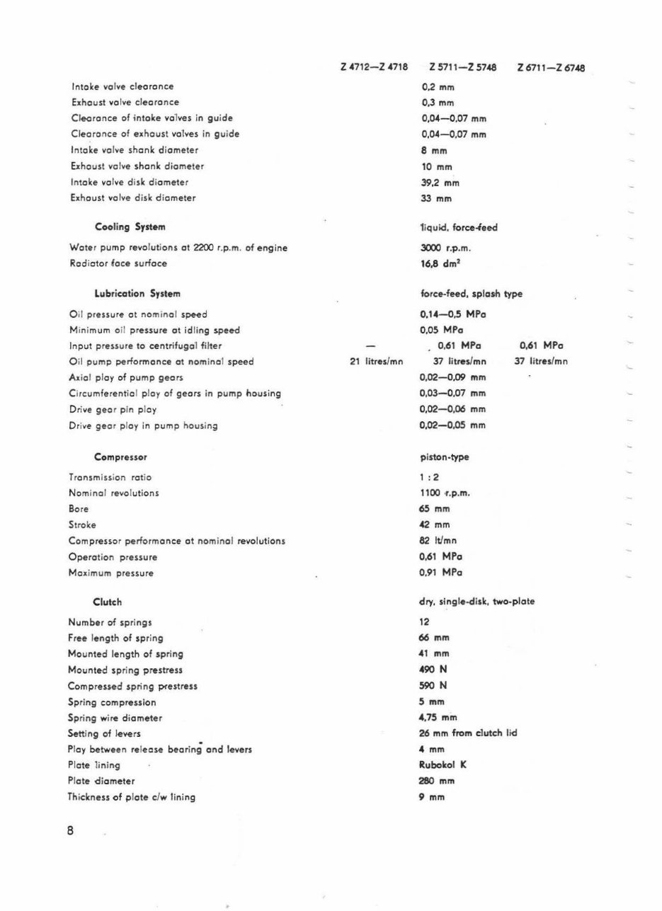
lntoke vo lve deoronce Exhaust vol ve cleoronce Cl eoronce of fotoke val ves in gu i de Cleoronce of exhoust vo 1ves in gui de lntoke va lve shonk di ameter Exhoust vo lve shonk diometer Int ake valve di sk di ameter Exhaust volve disk diameter Cooling System Weter pump revol ut ions ct 2200 r.p.m. of eng ine Rodiotor foce surf ace Lubrication System O il pressure ot nom in al s~d Minimum o il pressure ot id li ng speed Input pressure to c:entrifugo 1 fi lter O il pu mp performonc:e ct nomino'I speed Axial ploy of pump geors Circumferentia l p loy of gears in pump housing Drive geor pin pl oy Dri ve gea r ploy in pump housing Compressor Transmi ssion rat io Nomi na l revolutions Bore Stroke Compressor perfo r mance ct nomi na l revolutions Operat ion pressure Ma ximum pressure Clutch Numbe r of springs Free length of sprin g Mounted length of spring Mounted sp ring prestress Compressed spring prest ress Spring compression Spri ng wire diameter Sett i ng of l evers Ploy between release beari ng ond levers Plote li ni ng Plote di ameter Th ickness of pl ate clw linin g 8 Z 4712-Z 4718 21 litres/mn Z 5711-Z 5748 0,2 mm 0,3 mm 0,04-0,07 mm 0,04-0,07 mm 8 mm 10 mm 39,2 mm 33 mm 1l quid, force-lee-cl 3000 r.p.m. 16,8 dm 2 Z 6711-Z 6748 force-feed, splash type 0,14-0,5 MPa 0,05 MPo 0.61 MPa 37 litres/mn 0,02-0,09 mm 0,03-0.07 mm 0,02-0,06 mm 0.02-0.os mm piston-type 1 : 2 1100 .,.p.m. 65 mm 42 mm 82 lt/mn 0, 61 MPa 0,91 MPa 0,61 MPa 37 litres/mn dry. sing le-disk, two-plate 12 66 mm -41 mm 490 N 590 N 5 mm 4,75 mm 26 mm from clutch lid -4 mm Rubokol K 280 mm 9 mm
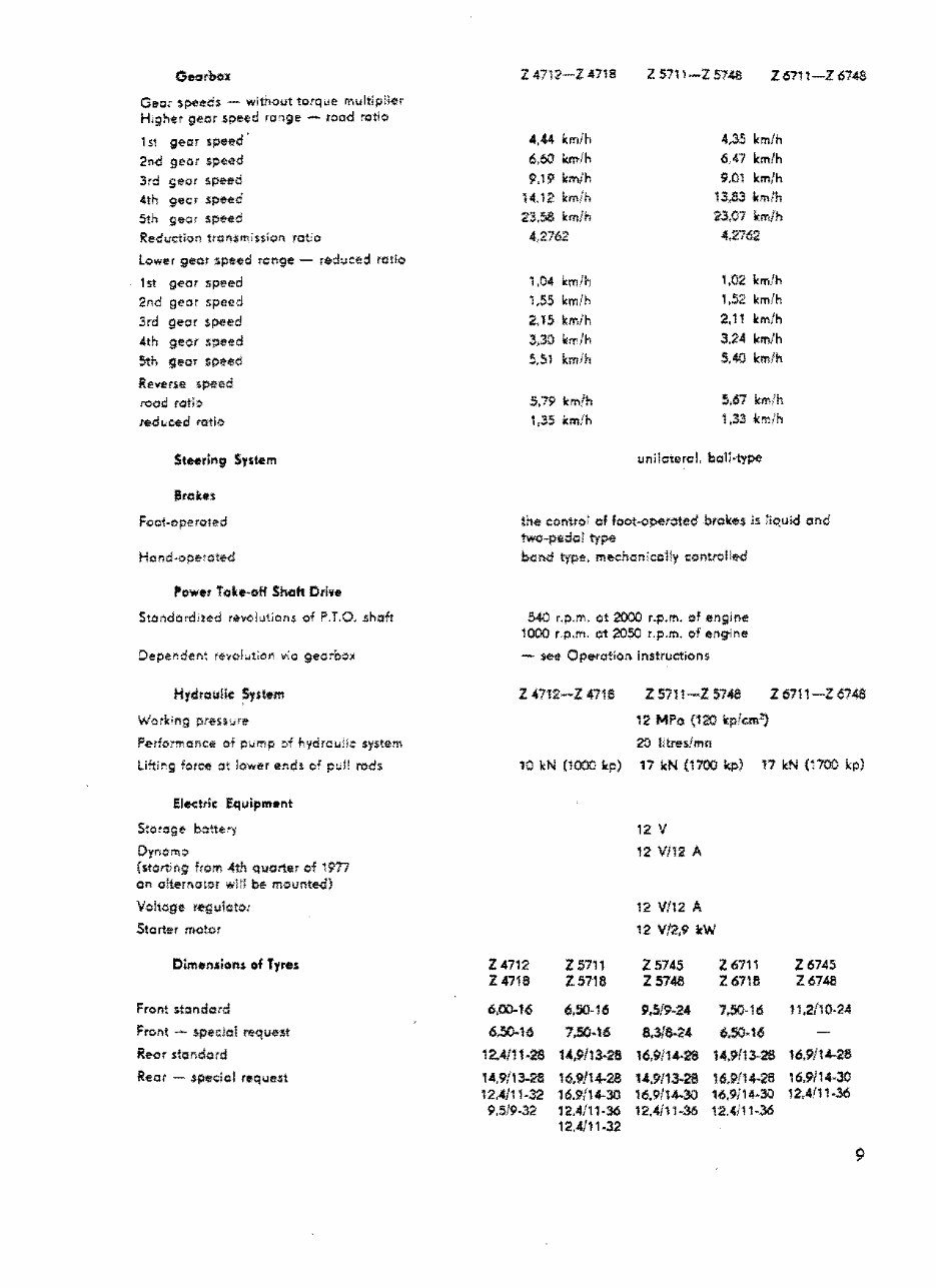
Gee; speeds - witr>.01Jt totq..ie multip:ier H,ghet geor $peed ro.,ge - rood r.oti¢:i 1 s1 gecn speed ' 2-:i<l geor speed 3rd seor s~eci 4th gecr speed 5th geor speed Reductlun tfOfl$mission ratio Lower gear speed ron9e - rt:dl.lced ratio 1st gear speed 2nd geor speed 3rd gear $peed 4th 9eor speed 5th gear speed Reverse speed read rat;:> ~i.ced ratio Steerlrtg System Btckes Foo1-opero1ed flower iolte-off Slu:ih Drive Stondord,ted r;}volutions of ?.T.O, .shaft H7draulie ~stem Work;ng pr-est1.1re Perfonrance of p;.,mp :,f +,ydrcu:ic system li~irg fotef! ot lower etu;lt o; p:.!! rods Electric Equipm•nt S;otoge botte")' Dyr;c-mo fstort:ng from 4t'1 quarter of 1977 an o!ternct:)r wii! b~ mounte<i} V.o!tc;ge r-egu1cto: Stort-er motor Dim•nsion$ of Tyres Front $t:indcrd Front ~ spe::lal ~que:st Reor sfcir.dord Rear - special ritquetit Z4712-Z4718 Z571l-Z5748 Z67it-Z674S 4,44 km/h 4,35 km/h 6,60 krt>lh 6.47 km/h 9.19 km/h 9,Q1 km/h 14.12 km!h 13,83 tun!h 23,58 kmfh ?3,07 km/h 4,2762 4,2762 1,04 kmlh 1,02 km/h 1,55 km/h 1 ,52 km/h 2,15 krrJh 2,11 km/h 3,30 li:ir /h 3.24 km/h 5,51 kmfh 5,40 km/h 5,79 km/h 5,67 km/h 1,35 icm!h 1,33 k~:n unilateroL 1::a.:i1i·type the eontro: of foot-operated brokes ls iiquid and twc-pedol ty~ bel\d type, mechonico11y convelle</ 540 r.p.m. ot 2000 r.p.m. of engine 1000 r.p.m. i;rt 2050 r.p.m. of engine - se;r Ope-ration instructions Z 47t2-Z 471S Z571t-Z $7-ia Z6711-Z674S 12 MPo (120 kpfcm1) 20 l1treslmn 10 kN (1000 lr.p) 17 kN (1700 kp) 17 It..._, (':100 kp) 12 v 12 Vi12 A 12 Vft2 A 12 V/2,9 kW z 4712 z 5711 Z5745 z 6711 Z6745 z 4716 Z.5718 Z5748 Z6718 Z6748 6,00-16 6,50-16 9,5/9~24 7,.50-16 11,2/10-24 6,SO..i6 7.SO~t6 B.31~• 6.50·16 12.4/i1·28 1<,9113-28 16,9114-28 14.9{13-28 16,9/14-28 14,9/13-28 16,9/14-28 1-4,9/13-28 16,9/1+.28 16,9/14-30 i2.-4l11·32 16.9/14-30 16.9114-30 16,9ii4-3J 12,4.111-36 9,5/9-32 12.4/11·36 12,4/11·36 12.-4111~36 12,4/11-32 9
Zetor 4712/4718/5711/5718/5745/5748/6711/6718/6745/6748 Tractors OEM Service & Repair Manual
Models covered:
Zetor 4712
Zetor 4718
Zetor 5711
Zetor 5718
Zetor 5745
Zetor 5748
Zetor 6711
Zetor 6718
Zetor 6745
Zetor 6748
The Zetor 4712/4718/5711/5718/5745/5748/6711/6718/6745/6748 Tractors OEM Service & Repair Manual provides detailed technical information essential for maintaining and repairing these reliable tractor models. Authored by Zetor, this manual includes comprehensive procedures, wiring diagrams, and precise specifications to ensure accurate and efficient servicing.
Designed for professional mechanics and experienced tractor operators, this manual covers a wide range of critical topics. It offers step-by-step instructions for engine diagnostics, hydraulic system maintenance, and electrical system repairs. The manual ensures all maintenance and repair tasks are performed to factory standards, preserving the performance and reliability of your Zetor tractor.
Available in a convenient digital format, this manual allows for easy access on various devices, making it a practical resource in both the workshop and the field. The Zetor 4712/4718/5711/5718/5745/5748/6711/6718/6745/6748 Tractors OEM Service & Repair Manual is an indispensable tool for ensuring the longevity and optimal functionality of your equipment.
Printable: Yes Language: English Compatibility: Pretty much any electronic device, incl. PC & Mac computers, Android and Apple smartphones & tablet, etc. Requirements: Adobe Reader (free)
Recently Viewed
5,521,897Happy Clients
2,594,462eManuals
1,120,453Trusted Sellers
15Years in Business
Price:
Actual Price:
Zetor 4712/4718/5711/5718/5745/5748/6711/6718/6745/6748 Tractors OEM Service & Repair Manual