White 2-70 / 2-85 / 2-105 / 2-150 Tractor Service & Repair Manual
What's Included?
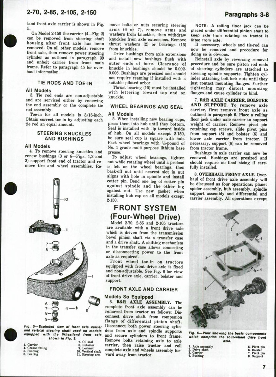
Lifetime Access
Fast Download Speeds
Online & Offline Access
Access PDF Contents & Bookmarks
Full Search Facility
Print one or all pages of your manual
SHOP MANUAL MODELS 2-70 2-85 2-105 2-150 Tractor serial number plate for Model 2-70 tractors is located on rear side of instrument panel support. Tractor serial number plate for Models 2-85, 2-105 and 2-150 is located on left rear side of main frame. Engine serial number for Model 2-70 is stamped directly below alternator along outer edge of timing gear cover mounting flange. Engine serial number for Models 2-85 and 2-105 is stamped on engine block directly below the injection pump. Engine serial number plate for Model 2-150 is located on right side of engine. INDEX (By Starting Paragraph) Model 2-70 BRAKES 274 CARBURETOR 124 CLUTCH Engine clutch adjustment 188 Engine clutch R&R 189 Engine clutch overhaul 190 COOLING SYSTEM Water pump 181 Radiator 179 Thermostat 185 DIESEL SYSTEM Fuel supply pump Fuel system bleeding 129 Governor adjust 161 Nozzles, testing 134 Nozzles, R&R 133 Nozzles, overhaul 139 Injection pump, R&R 157 Injection pump, timing 156 Troubleshooting 128 DIFFERENTIAL Overhaul 247 Remove and reinstall 245 ELECTRICAL Distributor 187B Alternator 187F Regulator 187F Starting motor 187G ENGINE Assembly, R&R 46 Auxiliary drive shaft Cam followers 52 Camshaft 57 Connecting rod and bearings 64 Crankshaft and bearings 65 Cylinder head 47 Cylinder sleeves 59 Flywheel 68 Models 2-85, 2-105 276 188 189 191, 193 182 179 186 173 131 170 149 148 154 169 168 128 251, 255 248, 252 187F 187F 187G 73 85 77 83 90 91 74 87 94 Model 2-150 276 188 189 193 183 180 187 129 165 142 141 147 164 163 128 251 248 187F 187F 187G 98 102 110 115 116 99 120
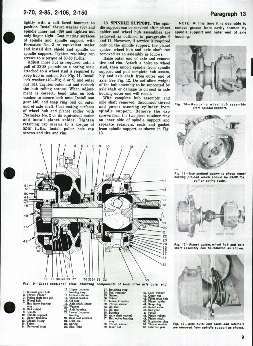
INDEX (CONT.) POWER TAKE-OFF Control valve Clutch overhaul Drive shaft, R&R . . . PTO unit, R&R TRANSFER DRIVE.. TRANSMISSION Bevel pinion shaft. . . Countershaft Input shaft. Lubrication system. . Reverse idler Shifter rails & forks . Top cover TURBOCHARGER .. [odel 2-70 287 286 290 25 222 219 215 211 221 217 212 Models 2 85, 2-105 296 294 292 293 25 240 239 237 225 244 233 232 96 Model 2-150 296 294 292 293 240 239 237 225 244 233 232 CONDENSED SERVICE DATA Model Models Model 2-70 2-85,2-105 2-150 GENERAL Engine Make Own Perkins Own Cylinders, No. Of 6 6 6 Cylinder Bore-In 3-3/4G,3-7/8D 3 7/8 4-3/4 Stroke-In 4 5 5V2 Displacement—Cubic In.: Non Diesel 265 Diesel 283 354 585 Compression Ratio: Gasoline 8.5:1 Diesel 16.5:1 16:1 15.3:1 Main Bearings, No. Of 7 7 4 Cylinder Sleeves, Type Wet Dry Forward Speeds, No. Of 6 6 6 Battery Terminal Grounded Neg. Neg. Neg. TUNE-UP Firing Order 1-5 3-6-2-4 1-5-3-6-2-4 1-5-3-6-2 4 Valve Tappet Gap Inlet: Non-Diesel—Inch 0.020 Cold Diesel-Inch 0.030 Cold 0.010 Hot 0.010 Cold Valve Tappet Gap, Ex.: Non-Diesel-Inch 0.030 Cold Diesel-Inch 0.030 Cold 0.010 Hot 0.020 Cold Valve Face Angle, Degrees 44 V2 45 46 Valve Seat Angle, Degrees 45 45 45 Ignition Distributor Make HoUey Ignition Distributor Model D-2563AA Alternator Make D-R D-R D-R Starting Motor Make D-R D-R D-R Starting Motor Model See Par. 187G See Par. 187G See Par. 187G Ignition Distr. Contact Gap 0.025 Ignition Distributor Timing See Par. 187C Injection Pump Make Roosa CAV Roosa Injection Pump Timing (Static) 4®BTDC 30°BTDC 4°ATDC Carburetor Make Marvel- Schebler Carburetor Model TSX807 Engine Low Idle Rpm 800 800 800 Engine High Idle Rpm 2430G,2450D 2380 2305-2365 Engine Rated Rpm 2200 2200 2200 Pto Rpm At Engine Rated Rpm: 540RpmPto 550 550 550 1000 Rpm Pto 994 994 994
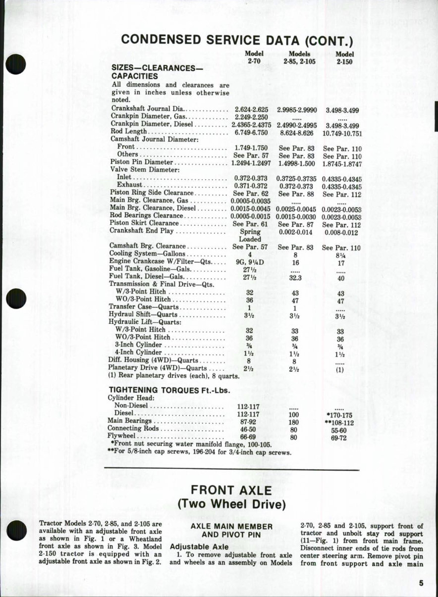
CONDENSED SERVICE DATA (CONT.) Model 2-70 SIZES-CLEARANCES- CAPACITIES All dimensions and clearances are given in inches unless otherwise noted. Crankshaft Journal Dia 2.624-2.625 Crankpin Diameter, Gas 2.249-2.250 Crankpin Diameter, Diesel 2.4365 2.4375 Rod Length 6.749 6.750 Camshaft Journal Diameter: Front 1.749-1.750 Others See Par. 57 Piston Pin Diameter 1.2494-1.2497 Valve Stem Diameter: Inlet 0.372 0.373 Exhaust 0.371 0.372 Piston Ring Side Clearance See Par. 62 Main Brg. Clearance, Gas 0.0005 0.0035 Main Brg. Clearance, Diesel 0.0015 0.0045 Rod Bearings Clearance 0.0005 0.0015 Piston Skirt Clearance See Par. 61 Crankshaft End Play Spring Loaded Camshaft Brg. Clearance See Par. 57 Cooling System—Gallons 4 Engine Crankcase W/Filter—Qts Fuel Tank, Gasoline—Gals Fuel Tank, Diesel—Gals Transmission & Final Drive—Qts. W/3-Point Hitch WO/3 Point Hitch Transfer Case—Quarts Hydraul Shift—Quarts Hydraulic Lift—Quarts: W/3 Point Hitch WO/3 Point Hitch 3-Inch Cylinder 4-Inch Cylinder Diff. Housing (4WD)—Quarts Planetary Drive (4WD)—Quarts (1) Rear planetary drives (each), 8 quarts. 9G. 9V4D 27 Vz 27 Vz 32 36 1 3V2 32 36 ¥4 Vk 8 2V2 Models 2-85. 2-105 Model 2-150 2.9985-2.9990 3.498-3.499 2.4990-2.4995 8.624-8.626 3.498-3.499 10.749-10.751 See Par. 83 See Par. 110 See Par. 83 See Par. 110 1.4998-1.500 1.8745-1.8747 0.3725-0.3735 0.4335 0.4345 0.372-0.373 0.4335-0.4345 See Par. 88 See Par. 112 0.0025-0.0045 0.0023-0.0053 0.0015-0.0030 0.0023-0.0053 See Par. 87 See Par. 112 0.002-0.014 0.008-0.012 See Par. 83 8 16 43 47 1 36 '^ lVf 8 See Par. 110 8V4 17 <: 40 43 33 36 IVi TIGHTENING TORQUES Ft.-Lbs. Cylinder Head: Non-Diesel 112-117 Diesel 112-117 Main Bearings 87-92 Connecting Rods 46-50 Flywheel 66-69 •Front nut securing water manifold flange, 100-105. ••For 5/8-inch cap screws, 196-204 for 3/4-inch cap screws. 100 180 80 80 •170-175 ••108-112 55^ 69-72 Tractor Models 2-70, 2-85, and 2-105 are avaUable with an adjustable front axle as shown in Fig. 1 or a Wheatland front axle as shown in Fig. 3. Model 2-150 tractor is equipped with an adjustable front axle as shown in Fig. 2. FRONT AXLE (Two Wheel Drive) AXLE MAIN MEMBER AND PIVOT PIN Adjustable Axle 1. To remove adjustable front axle and wheels as an assembly on Models 2-70, 2-85 and 2-105, support front of tractor and unbolt stay rod support (11—Fig. 1) from front main frame. Disconnect inner ends of tie rods from center steering arm. Remove pivot pin from front support and axle main
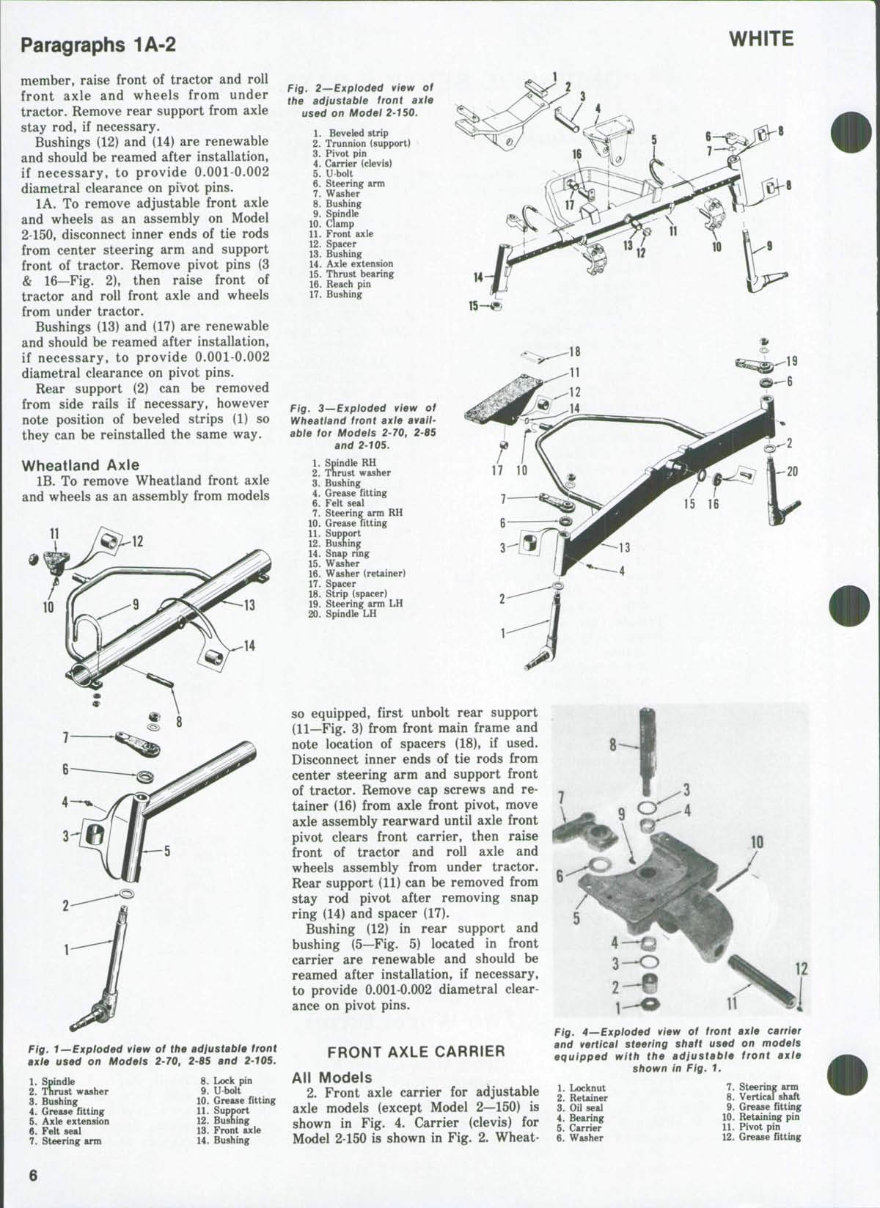
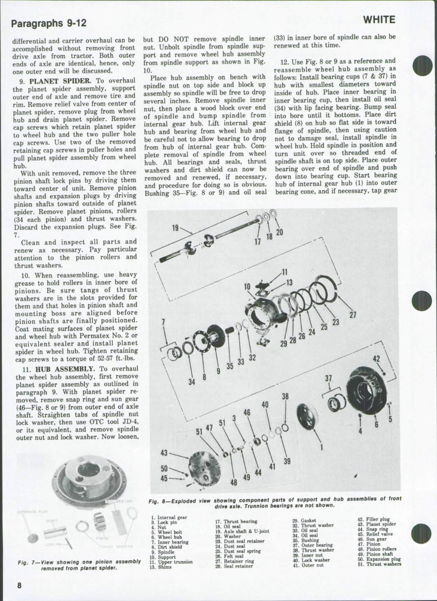
Paragraphs 1A-2 WHITE member, raise front of tractor and roll front axle and wheels from under tractor. Remove rear support from axle stay rod, if necessary. Bushings (12) and (14) are renewable and should be reamed after installation, if necessary, to provide 0.001-0.002 diametral clearance on pivot pins. lA. To remove adjustable front axle and wheels as an assembly on Model 2-150, disconnect inner ends of tie rods from center steering arm and support front of tractor. Remove pivot pins (3 & 16—Fig. 2), then raise front of tractor and roll front axle and wheels from under tractor. Bushings (13) and (17) are renewable and should be reamed after installation, if necessary, to provide 0.001-0.002 diametral clearance on pivot pins. Rear support (2) can be removed from side rails if necessary, however note position of beveled strips (1) so they can be reinstalled the same way. Wheattand Axle IB. To remove Wheatland front axle and wheels as an assembly from models 11 Fig. 2—Exploded view of the adjustable front axle used on Model 2-T50. 1. Beveled strip 2. Trunnion (support) 3. Pivot pin 4. Carrier (clevis) 5. U bolt 6. Steering arm 7. Washer 8. Bushing 9. Spindle 10. Clamp 11. Front axle 12. Spacer 13. Bushing 14. Axle extension 15. Thrust bearing 16. Reach pin 17. Bushing 1. Spindle 2. Thrust washer 3. Bushing 4. Grease fitting 5. Axle extension 6. Felt seal 7. Steering arm 8. Lock pin 9. U bolt 10. Grease fitting 11. Support 12. Bushing 13. Front axle 14. Bushing Fig^ 3—Exploded view of Wheatland front axle avail- able for Models 2-70, 2-85 and 2-105. 1. Spindle RH 2. Tnrust washer 3. Bushing 4. Grease fitting 6. Felt seal 7. Steering arm RH 10. Grease fitting 11. Support 12. Busnin^ 14. Snap nng 15. Washer 16. Washer (reUiner) 17. Spacer 18. Strip (spacer) 19. Steering arm LH 20. Spindle LH Fig. 1—Exploded view of the adfustablB front axle used on Models 2-70, 2-65 and 2-105. so equipped, first unbolt rear support (11—Fig. 3) from front main frame and note location of spacers (18), if used. Disconnect inner ends of tie rods from center steering arm and support front of tractor. Remove cap screws and re- tainer (16) from axle front pivot, move axle assembly rearward until axle front pivot clears front carrier, then raise front of tractor and roll axle and wheels assembly from under tractor. Rear support (11) can be removed from stay rod pivot after removing snap ring (14) and spacer (17). Bushing (12) in rear support and bushing (5—Fig. 5) located in front carrier are renewable and should be reamed after installation, if necessary, to provide 0.001 0.002 diametral clear- ance on pivot pins. FRONT AXLE CARRIER All Models 2. Front axle carrier for adjustable axle models (except Model 2—150) is shown in Fig. 4. Carrier (clevis) for Model 2450 is shown in Fig. 2. Wheat- Fig, 4—Exploded view of front axle carrier and vertical steering shaft used on models equipped with the adjustable front axle shown in Fig. 1, 1. Locknut 2. Retainer 3. Oil seal 4. Bearing 5. Carrier 6. Washer 7. Steering arm 8. Vertical shaft 9. Grease fitting 10. Retaining pin 11. Pivot pin 12. Grease fitting
2-70, 2-85, 2-105, 2-150 land front axle carrier is shown in Fig. 5. On Model 2-150 the carrier (4—Fig. 2) can be removed from steering shaft housing after front axle has been removed. On all other models, remove front axle, then remove power steering cylinder as outlined in paragraph 39 and unbolt carrier from front main frame. Refer to paragraph 45 for over- haul information. i TIE RODS AND TOE-IN All Models 3. Tie rod ends are non adjustable and are serviced either by renewing the end assembly or the complete tie rod assembly. Toe-in for all models is 3/16-inch. Obtain correct toe-in by adjusting each tie rod an equal amount. i STEERING KNUCKLES AND BUSHINGS All Models 4. To remove steering knuckles and renew bushings (3 or 8—Figs. 1.2 and 3) support front end of tractor and re- move tire and wheel assemblies. Re- !1 move bolts or nuts securing steering arms (6 or 7), remove arms and washers from knuckles, then withdraw knuckles from axle extensions. Remove thrust washers (2) or bearings (15) from knuckles. Drive bushings from axle extensions and install new bushings flush with outer ends of bore. Clearance of knuckle in bushings should be 0.002- 0.006. Bushings are presized and should not require reaming if installed with a suitable piloted arbor. Thrust bearing (15) must be installed with lettering toward top end on knuckle. WHEEL BEARINGS AND SEAL All Models 5. When installing new bearing cups, press them into hub until they bottom. Seal is installed with lip toward inside of hub. On all models except 2-150, be sure seal cup is square with hub. Pack wheel bearings with Vz-pound of No. 1 grade multi-purpose lithium base grease. To adjust wheel bearings, tighten nut while rotating wheel until a preload is felt on the wheel bearings, then back-off nut until nearest slot in nut aligns with hole in spindle and install cotter pin. Bend one leg of cotter pin against spindle and the other leg against nut. Use new gasket when installing hub cap on all models except 2-150. FRONT SYSTEM (Four-Wheel Drive) Model 2-70, 2-85 and 2-105 tractors are available with a front drive axle which is driven from the transmission bevel pinion shaft via a transfer case and a drive shaft. A shifting mechanism in the transfer case allows connecting or disconnecting power to the front axle as required. Front wheel toe-in on tractors equipped with front drive axle is fixed and non-adjustable. See Fig. 6 for view of front drive axle, carrier, bolster and support. FRONT AXLE AND CARRIER Models So Equipped 6. R&R AXLE ASSEMBLY. The complete front axle assembly can be removed from tractor as follows: Dis- connect drive shaft from companion — flange of differential pinion shaft. fig. 5—Exploded view of front axle carrier Disconnect both power steering cylin- and vertical steering shaft used on models ders from axle and spindle supports eouipped M"'"* "*^ u/fiA*#iaM^ 4.M..« ^.I. J « . « . . . Paragraphs 3-8 -10 1. Carrier I* BuXg *" «. Bearing 8^ Reuiner lo! i^iSilshaft u . Steering arm p ppt cylinders to front frame. Remove bolts retaining axle to axle carrier, then raise tractor and roU complete axle and wheels assembly for- vard away from tractor. NOTE: A rolling floor jack can be placed under differential pinion shaft to keep axle from rotating as tractor is lifted from axle. If necessary, wheels and tie-rod can now be removed and procedure for doing so is obvious. Reinstall axle by reversing removal procedure and be sure piston rod ends of steering cylinders are attached to steering spindle supports. Tighten cyl- inder attaching bolt lock nuts until they just contact mounting flanges. Further tightening may distort mounting flanges and cause cylinder to bind. 7. R&R AXLE CARRIER, BOLSTER AND SUPPORT, To remove axle carrier, first remove front axle as outlined in paragraph 6. Place a rolling floor jack under axle carrier to support weight of carrier. Remove pivot pin retaining cap screws, slide pivot pins from support (8) and bolster (6) and lower axle carrier from tractor. If necessary, support (8) can be removed from tractor frame. Bushings in axle carrier can now be renewed. Bushings are presized and should require no final sizing if care- fully installed. 8. OVERHAUL FRONT AXLE. Over- haul of front drive axle assembly will be discussed as four operations; planet spider assembly, hub assembly, spindle support assembly and differential and carrier assembly. All operations except Fig. B^view showing the basic components which comprise the four-wheel drive front axle. 1. Axle assembly 2. Drive shaft 3. Carrier 4. Bushing 5. Pivot pin 6. Bolster 7. Pivot pin 8. Support
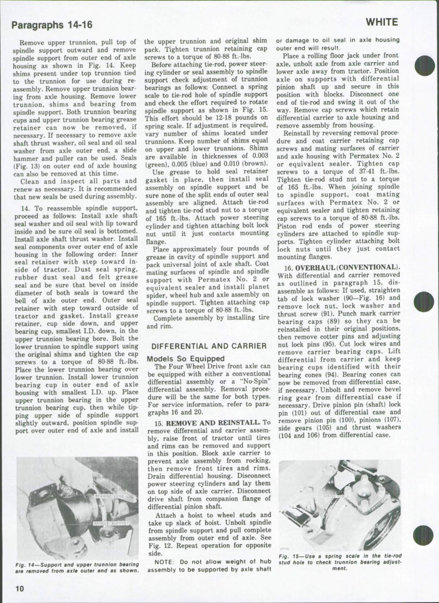
Paragraphs 9-12 differential and carrier overhaul can be accomplished without removing front drive axle from tractor. Both outer ends of axle are identical, hence, only one outer end will be discussed. 9. PLANET SPIDER. To overhaul the planet spider assembly, support outer end of axle and remove tire and rim. Remove relief valve from center of planet spider, remove plug from wheel hub and drain planet spider. Remove cap screws which retain planet spider to wheel hub and the two puller hole cap screws. Use two of the removed retaining cap screws in puller holes and pull planet spider assembly from wheel hub. With unit removed, remove the three pinion shaft lock pins by driving them toward center of unit. Remove pinion shafts and expansion plugs by driving pinion shafts toward outside of planet spider. Remove planet pinions, rollers (34 each pinion) and thrust washers. Discard the expansion plugs. See Fig. 7. Clean and inspect all parts and renew as necessary. Pay particular attention to the pinion rollers and thrust washers. 10. When reassembling, use heavy grease to hold rollers in inner bore of pinions. Be sure tangs of thrust washers are in the slots provided for them and that holes in pinion shaft and mounting boss are aligned before pinion shafts are finally positioned. Coat mating surfaces of planet spider and wheel hub with Permatex No. 2 or equivalent sealer and install planet spider in wheel hub. Tighten retaining cap screws to a torque of 52-57 ft.-lbs. 11. HUB ASSEMBLY. To overhaul the wheel hub assembly, first remove planet spider assembly as outlined in paragraph 9. With planet spider re- moved, remove snap ring and sun gear (46—Fig. 8 or 9) from outer end of axle shaft. Straighten tabs of spindle nut lock washer, then use OTC tool JD-4, or its equivalent, and remove spindle outer nut and lock washer. Now loosen. but DO NOT remove spindle inner nut. Unbolt spindle from spindle sup- port and remove wheel hub assembly from spindle support as shown in Fig. 10. Place hub assembly on bench with spindle nut on top side and block up assembly so spindle will be free to drop several inches. Remove spindle inner nut, then place a wood block over end of spindle and bump spindle from internal gear hub. Lift internal gear hub and bearing from wheel hub and be careful not to allow bearing to drop from hub of internal gear hub. Com- plete removal of spindle from wheel hub. All bearings and seals, thrust washers and dirt shield can now be removed and renewed, if necessary, and procedure for doing so is obvious. Bushing 35—Fig. 8 or 9) and oil seal 19 WHITE (33) in inner bore of spindle can also be renewed at this time. 12. Use Fig. 8 or 9 as a reference and reassemble wheel hub assembly as follows: Install bearing cups (7 & 37) in hub with smallest diameters toward inside of hub. Place inner bearing in inner bearing cup, then install oil seal (34) with lip facing bearing. Bump seal into bore until it bottoms. Place dirt shield (8) on hub so flat side is toward flange of spindle, then using caution not to damage seal, install spindle in wheel hub. Hold spindle in position and turn unit over so threaded end of spindle shaft is on top side. Place outer bearing over end of spindle and push down into bearing cup. Start bearing hub of internal gear hub (1) into outer bearing cone, and if necessary, tap gear 45 Fig, B—Exploded view showing component parts of support and hub assemblies of front drive axle. Trunnion bearings are not shown. Fig. 7—y\ew showing one pinion assembly removed from planet spider. 1. Internal gear 3. Lock pin 4. Nut 5. Wheel bolt 6. Wheel hub 7. Inner bearing 8. Dirt shield 9. Spindle 10. Support 11. Upper trunnion 13. Shims 17. Thrust bearing 18. Oil seal 19. Axle shaft & U-joint 20. Washer 23. Dust seal retainer 24. Dust seal 25. Dust seal spring 26. Felt seal 27. Retainer ring 28. Seal retainer 29. Gasket 32. Thrust washer 33. Oil seal 34. Oil seal 35. Bushing 37. Outer bearing 38. Thrust washer 39. Inner nut 40. Lock washer 41. Outer nut 42. Filler plug 43. Planet spider 44. Snap ring 45. Relief valve 46. Sun gear 47. Pinion 48. Pinion rollers 49. Pinion shaft 50. Expansion plug 51. Thrust wasners
2-70, 2-85, 2-105, 2-150 lightly with a soft faced hammer to position. Install thrust washer (38) and spindle inner nut (39) and tighten nut only finger tight. Coat mating surfaces of spindle and spindle support with Permatex No. 2 or equivalent sealer and install dirt shield and spindle on spindle support. Tighten retaining cap screws to a torque of 80-88 ft.-lbs. Adjust inner nut as required until a pull of 33-38 pounds on a spring scale attached to a wheel stud is required to keep hub in motion. See Fig. 11. Install lock washer (40—Fig. 8 or 9) and outer nut (41). Tighten outer nut and recheck the hub rolling torque. When adjust- ment is correct, bend tabs on lock washer to secure both nuts. Install sun gear (46) and snap ring (44) on outer end of axle shaft. Coat mating surfaces of wheel hub and planet spider with Permatex No. 2 or its equivalent sealer and install planet spider. Tighten retaining cap screws to a torque of ^-57 ft.-lbs. Install puller hole cap screws and tire and rim. Paragraph 13 13. SPINDLE SUPPORT. The spin die support can be serviced after planet spider and wheel hub assemblies are removed as outlined in paragraphs 9 and 11. However, if service is required only on the spindle support, the planet spider, wheel hub and axle shaft can removed as an assembly as follows: Raise outer end of axle and remove tire and rim. Attach a hoist to wheel stud, then unbolt spindle from spindle support and pull complete hub assem- bly and axle shaft from outer end of axle. See Fig. 12. Do not allow weight of the hub assembly to be supported by axle shaft or damage to oil seal in axle housing outer end will result. With complete hub assembly and axle shaft removed, disconnect tie-rod and power steering cylinder from spindle support. Remove the cap screws from the two-piece retainer ring on inner side of spindle support and separate retainers, seals and gasket from spindle support as shown in Fig. 13. 29 42 41 40 39 38 37 36 3534 33 32 31 30 Fig. 9—Cross-sectional view showing components of front drive axle outer end. 1. Internal gear hub 2. Thrust washer 3. Pinion shaft lock pin 6. Wheel hub 7. Hub inner bearing assy. 8. Dirt shield 9. Spindle 10. Spindle support 11. Upper trunnion 12. Grease fitting 13. Shims 14. Universal joint 16. Upper trunnion bearing assy. 16. Grease retainer 17. Thrust washer 18. Oil seal 19. Axle shaft (inner) 20. Washer 21. Axle housing 22. Lower trunnion bearing 23. Dust seal retainer 24. Dust seal 25. Spring 26. Seal (felt) 27. ReUining ring 28. Seal retainer 29. Gasket 30. Shims 31. Lower trunnion 32. Thrust washer 33. Oil seal 34. Oil seal 35. Bushing 36. Axle shaft (outer) 37. Hub outer bearing assy, 38. Thrust washer 89. Inner nut 40. Lock washer 41. Outer nut 42. Filler plug hole 43. Planet spider 44. Snap ring 45. ReUef valve 46. Sun gear 47. Pinion 48. Pinion rollers 49. Pinion shaft 50. Expansion plug 51. Thrust washer S&. Internal gear NOTE; At this time it is desirable to remove grease from cavity formed by spindle support and outer end of axle housing. Fig. 10—Removing wheel hub assembly from spindle support. Fig. 11—Use method shown to cfteck wheel bearing preioad which should be 33-39 lbs. 14 pull on spring scale. Fig. 12—Planet sp/tfor, wheel hub and axle shaft assembly can be removed as shown. Fig. 1$—Axle outer end seals and retainers are removed from spindle support as shown.
Paragraphs 14-16 Remove upper trunnion, pull top of spindle support outward and remove spindle support from outer end of axle housing as shown in Fig. 14. Keep shims present under top trunnion tied to the trunnion for use during re- assembly. Remove upper trunnion bear- ing from axle housing. Remove lower trunnion, shims and bearing from spindle support. Both trunnion bearing cups and upper trunnion bearing grease retainer can now be removed, if necessary. If necessary to remove axle shaft thrust washer, oil seal and oil seal washer from axle outer end, a slide hammer and puller can be used. Seals (Fig. 13) on outer end of axle housing can also be removed at this time. Clean and inspect all parts and renew as necessary. It is recommended that new seals be used during assembly. 14. To reassemble spindle support, proceed as follows: Install axle shaft seal washer and oil seal with lip toward inside and be sure oil seal is bottomed. Install axle shaft thrust washer. Install seal components over outer end of axle housing in the following order: Inner seal retainer with step toward in- side of tractor. Dust seal spring, rubber dust seal and felt grease seal and be sure that bevel on inside diameter of both seals is toward the bell of axle outer end. Outer seal retainer with step toward outside of tractor and gasket. Install grease retainer, cup side down, and upper bearing cup, smallest LD. down, in the upper trunnion bearing bore. Bolt the lower trunnion to spindle support using the original shims and tighten the cap screws to a torque of 80-88 ft.-lbs. Place the lower trunnion bearing over lower trunnion. Install lower trunnion bearing cup in outer end of axle housing with smallest LD. up. Place upper trunnion bearing in the upper trunnion bearing cup, then while tip- ping upper side of spindle support slightly outward, position spindle sup- port over outer end of axle and install fig, 14—Support and upper trunnion bearing are removed from axle outer end as shown. the upper trunnion and original shim pack. Tighten trunnion retaining cap screws to a torque of 80-88 ft.-lbs. Before attaching tie-rod, power steer- ing cylinder or seal assembly to spindle support check adjustment of trunnion bearings as follows: Connect a spring scale to tie-rod hole of spindle support and check the effort required to rotate spindle support as shown in Fig. 15. This effort should be 12-18 pounds on spring scale. If adjustment is required, vary number of shims located under trunnions. Keep number of shims equal on upper and lower trunnions. Shims are available in thicknesses of 0.003 (green), 0.005 (blue) and 0.010 (brown). Use grease to hold seal retainer gasket in place, then install seal assembly on spindle support and be sure none of the split ends of outer seal assembly are aligned. Attach tie-rod and tighten tie-rod stud nut to a torque of 165 ft.-lbs. Attach power steering cylinder and tighten attaching bolt lock nut until it just contacts mounting flange. Place approximately four pounds of grease in cavity of spindle support and pack universal joint of axle shaft. Coat mating surfaces of spindle and spindle support with Permatex No. 2 or equivalent sealer and install planet spider, wheel hub and axle assembly on spindle support. Tighten attaching cap screws to a torque of 80-88 ft.-lbs. Complete assembly by installing tire and rim. DIFFERENTIAL AND CARRIER Models So Equipped The Four Wheel Drive front axle can be equipped with either a conventional differential assembly or a "No-Spin" differential assembly. Removal proce- dure will be the same for both types. For service information, refer to para- graphs 16 and 20. 15. REMOVE AND REINSTALL. To remove differential and carrier assem- bly, raise front of tractor until tires and rims can be removed and support in this position. Block axle carrier to prevent axle assembly from rocking, then remove front tires and rims. Drain differential housing. Disconnect power steering cylinders and lay them on top side of axle carrier. Disconnect drive shaft from companion flange of differential pinion shaft. Attach a hoist to wheel studs and take up slack of hoist. Unbolt spindle from spindle support and pull complete assembly from outer end of axle. See Fig. 12. Repeat operation for opposite side. NOTE: Do not allow weight of hub assembly to be supported by axle shaft WHITE or damage to oil seal in axle housing outer end will result. Place a rolling floor jack under front axle, unbolt axle from axle carrier and lower axle away from tractor. Position axle on supports with differential pinion shaft up and secure in this position with blocks. Disconnect one end of tie-rod and swing it out of the way. Remove cap screws which retain differential carrier to axle housing and remove assembly from housing. Reinstall by reversing removal proce- dure and coat carrier retaining cap screws and mating surfaces of carrier and axle housing with Permatex No. 2 or equivalent sealer. Tighten cap screws to a torque of 37-41 ft.-lbs. Tighten tie-rod stud nut to a torque of 165 ft.-lbs. When joining spindle to spindle support, coat mating surfaces with Permatex No. 2 or equivalent sealer and tighten retaining cap screws to a torque of 80-88 ft.-lbs. Piston rod ends of power steering cylinders are attached to spindle sup- ports. Tighten cylinder attaching bolt lock nuts until they just contact mounting flanges. 16. OVERHAUL (CONVENTIONAL). With differential and carrier removed as outlined in paragraph 15, dis- assemble as follows: If used, straighten tab of lock washer (90—Fig. 16) and remove lock nut, lock washer and thrust screw (91). Punch mark carrier bearing caps (89) so they can be reinstalled in their original positions, then remove cotter pins and adjusting nut lock pins (95). Cut lock wires and remove carrier bearing caps. Lift differential from carrier and keep bearing cups identified with their bearing cones (94). Bearing cones can now be removed from differential case, if necessary. Unbolt and remove bevel ring gear from differential case if necessary. Drive pinion pin (shaft) lock pin (101) out of differential case and remove pinion pin (100), pinions (107), side gears (105) and thrust washers (104 and 106) from differential case. Fig. 15—Use a spring scafe in the tie-rod stud hole to check trunnion bearing adjust- ment. 10
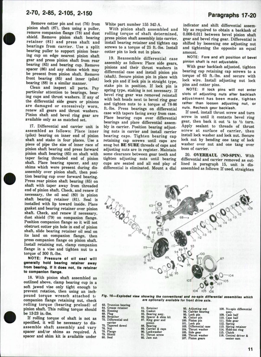
2-70, 2-85, 2-105, 2-150 Remove cotter pin and nut (76) from pinion shaft (87), then using a puller, remove companion flange (78) and dust shield. Remove pinion shaft bearing retainer (81) and press shaft and bearings from carrier. Use a split bearing puller to support pinion bear- ing cup on edge nearest pinion shaft gear and press pinion shaft from rear bearing (85) and bearing cup. Remove spacer (86) and any shims which may be present from pinion shaft. Remove front bearing (85) and inner (pilot) bearing (88) in a similar manner. Clean and inspect all parts. Pay particular attention to bearings, bear- ing cups and thrust washers. If any of the differential side gears or pinions are damaged or excessively worn, renew all gears and thrust washers. Pinion shaft and bevel ring gear are avaOable only as as matched set. 17. Differential and carrier unit is assembled as follows: Place inner (pilot) bearing on inner end of pinion shaft and stake in four places. Use a piece of pipe the size of inner race of pinion shaft bearing and press forward pinion shaft bearing (85) on shaft with taper facing threaded end of pinion shaft. Place bearing spacer, and any shims which were present during dis- assembly over pinion shaft, then posi- tion bearing cup over forward bearing. Press rear pinion shaft bearing (85) on shaft with taper away from threaded end of pinion shaft. Check, and renew if necessary, the oil seal (80) in pinion shaft bearing retainer (81). Seal is instaUed with lip toward inside. Place gasket and bearing retainer over pinion shaft. Check, and renew if necessary, dust shield (79) on companion flange. Position companion flange so it will not obstruct cotter pin hole in end of pinion shaft, slide bearing retainer oil seal on its land on companion flange, then press companion flange on pinion shaft. Install retaining nut, clamp companion flange in a vise and tighten nut to a torque of 300 ft.-lbs. NOTE: Pressure of oil seal will generally hold bearing retainer away from bearing. If It does not, tie retainer to companion fiange. 18. With pinion shaft assembled as outlined above, clamp bearing cup in a soft jawed vise only tight enough to prevent rotation, then using an inch- pound torque wrench attached U companion flange retaining nut, check rolling torque (bearing preload) of pinion shaft. This rolling torque should be 13-23 in.-lbs. If rolling torque of shaft is not as specified, it will be necessary to dis- assemble shaft assembly and vary spacer and/or shims as required. A spacer and shim kit is available under White part number 155 342-A. With pinion shaft assembled and rolling torque of shaft determined, press pinion shaft assembly into carrier, install bearing retainer and tighten cap screws to a torque of 25 ft.-lbs. Install cotter pin to lock nut in place. 19. Reassemble differential case assembly as follows: Place side gears, pinions and their thrust washers in differential case and install pinion pin (shaft). Secure pinion pin in place with lock pin and if lock pin is straight type, stake pin in position. If lock pin is spring type, staking is not necessary. If bevel ring gear was removed reinstall with bolt heads next to bevel ring gear and tighten nuts to a torque of 78-86 ft.-lbs. Press bearings on differential case with tapers facing away from case. Place bearing cups over differential bearings and place differential assem- bly in carrier. Position bearing adjust- ing nuts in carrier and install carrier bearing caps. Tighten bearing cap retaining cap screws until caps are snug but BE SURE threads of caps and adjusting nuts are in register. Maintain some clearance between gear teeth and tighten adjusting nuts until bearing cups are seated and all end play of differential is eliminated. Mount a dial Paragraphs 17-20 indicator and shift differential assem- bly as required to obtain a backlash of 0.008-0.011 between bevel pinion shaft gear and bevel ring gear. Differential is shifted by loosening one adjusting nut and tightening the opposite an equal amount. NOTE: Fore and aft position of bevel pinion shaft is not adjustable. With gear backlash adjusted, tighten bearing cap retaining cap screws to a torque of 65 ft.-lbs. and secure with lock wire. Install adjusting nut lock pins and cotter pins. NOTE: If lock pins will not enter slots of adjusting nuts after bacidash adjustment has been made, tighten rather than loosen adjusting nut, or nuts. Recheck gear backlash. If used, install thrust screw and turn screw in until it contacts bevel ring gear, then back it out V4 to Vi turn. Apply sealant to threads of thrust screw at surface of carrier, then install lock washer and lock nut. Secure lock nut by bending one tang of lock washer over nut and one tang over boss of carrier. 20. OVERHAUL (NI>SPIN). With differential and carrier removed as out- lined in paragraph 15, unit is dis- assembled as follows: If used, straighten 76 Fig. IS^Exploded view showing the conventional and no-spin differential assemblies which are optionally available for front drive axle. 63. Trunnion bearing 64. Grease retainer 65. Housing 68. Plug 69. Breather 70. Differential and carrier 75. Tapered dowel 76. Nut 78. Flange 79. Shield 80. Seal 81. ReUiner 84. Gasket 85. Bearing assy. 86. Spacer & shim kit 87. Ring gear and pinion 88. Bearing 89. Carrier & caps 90. Lockwasher 91. Thrust screw 92. Jam nut 93. Adjusting nut 94. Carrier tearing 95. Lock pin 96. Cotter pin 100. Pinion pin 101. Lock pin 103. Differential case 104. Thrust washer 105. Side gear 106. Thrust washer 107. Pinion gears 108. No spin differential assy. 109. Case half 110. Case half 111. Side gear 112. Spring 113. Sbring retainer 114. Hold-out ring 115. Clutch 116. Central driver & center cam 11
The White 2-70 / 2-85 / 2-105 / 2-150 Tractor Service & Repair Manual is a comprehensive factory manual designed for servicing, repairing, and troubleshooting the mentioned tractor models. It is suitable for professional mechanics and DIY enthusiasts alike.
This manual is available in digital format, either as a .PDF file or a .OVA file, and can be accessed instantly on your computer, tablet, or smartphone. It contains detailed instructions, along with numerous pages of photos, diagrams, and exploded views to guide you through each repair or maintenance procedure.
Common questions:
Q. Can I print out a page?
A. Yes, you have the option to print out a single page or the entire manual as per your requirement.
Q. Can I use this Manual on more than one computer?
A. Yes, this Manual can be used on multiple computers without any limitations.
Q. Is this a trial or a limited version?
A. No, this is the FULL Manual without any limitations or trial periods and can be used for life.
Q. Will this Manual expire in 12 months or will I have to pay a renewal fee?
A. NO, Absolutely not! You can continue to use this Manual for life without the need to renew or pay any extra.
Q. Will this Manual work on Windows & MAC computers?
A. Yes, it is fully compatible with all Windows & All MAC Computers.
For further details and to access the manual, please click on the provided button.
Recently Viewed
5,521,897Happy Clients
2,594,462eManuals
1,120,453Trusted Sellers
15Years in Business
Price:
Actual Price:
White 2-70 / 2-85 / 2-105 / 2-150 Tractor Service & Repair Manual