

White 2-135 & 2-155 Tractors Complete Workshop Service Repair Manual
What's Included?
Fast Download Speeds
Online & Offline Access
Access PDF Contents & Bookmarks
Full Search Facility
Print one or all pages of your manual
SHOP MANUAL
MODELS
2-135 2-155
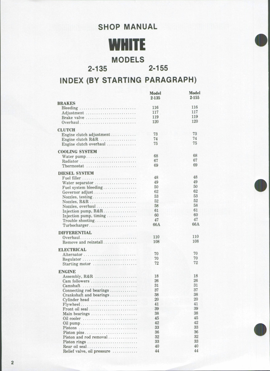
INDEX (BY STARTING PARAGRAPH)
BRAKES
Bleeding
Adjustment
Brake valve
Overhaul
CLUTCH
Engine clutch adjustment.
Engine clutch R&R
Engine clutch overhaul ...
COOLING SYSTEM
Water pump
Radiator
Thermostat
DIESEL SYSTEM
Fuel filler
Water separator
Fuel system bleeding ....
Governor adjust
Nozzles, testing
Nozzles, R&R
Nozzles, overhaul
Injection pump, R&R ....
Injection pump, timing ...
Trouble shooting
Turbocharger
DIFFERENTIAL
Overhaul
Remove and reinstall ....
ELECTRICAL
Alternator
Regulator
Starting motor —
ENGINE
Assembly, R&R
Cam followers
Camshaft
Connecting rod bearings .
Crankshaft and bearings .
Cylinder head
Flywheel
Front oil seal
Main bearings
Oil cooler
Oil pump
Pistons
Piston pins
Piston and rod removal..
Piston rings
Rear oil seal
Relief valve, oil pressure
Model
2-135
116
117
119
120
73
74
75
68
67
69
48
49
50
62
53
52
58
61
60
47
66A
110
108
70
70
72
18
26
31
37
38
20
41
39
38
45
42
33
36
32
33
40
44
Model
2-155
116
117
119
120
73
74
75
68
67
69
48
49
50
62
53
52
58
61
60
47
66A
no
108
70
70
72
18
26
31
37
38
20
41
39
38
45
42
33
36
32
33
40
44
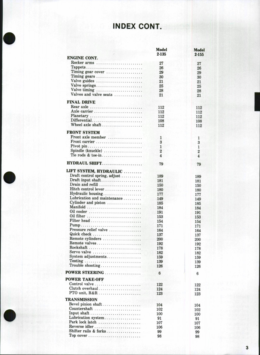
INDEX CONT.
Model
2-135
ENGINE CONT.
Rocker arms 27
Tappets 26
Timing gear cover 29
Timing gears 30
Valve guides 21
Valve springs 25
Valve timing 28
Valves and valve seats 21
FINAL DRIVE
Rear axle 112
Axle carrier 112
Planetary 112
Differential 108
Wheel axle shaft 112
FRONT SYSTEM
Front axle member 1
Front carrier 3
Pivot pin 1
Spindle (knuckle) 2
Tie rods & toe-in 4
HYDRAUL SHIFT 79
LIFT SYSTEM, HYDRAULIC
Draft control spring, adjust 189
Draft input shaft 181
Drain and refill 150
Hitch control lever 180
Hydraulic housing 177
Lubrication and maintenance 149
Cylinder and piston 185
Manifold 184
Oil cooler 191
Oil filter 153
Filter head 154
Pump 171
Pressure relief valve 164
Quick check 137
Remote cylinders 200
Remote valves 192
Rockshaft 178
Servo valve 182
System adjustments 159
Testing 139
Trouble shooting 126
POWER STEERING 6
POWER TAKE-OFF
Control valve 122
Clutch overhaul 124
PTO unit. R&R 123
TRANSMISSION
Bevel pinion shaft 104
Countershaft 102
Input shaft lOO
Lubrication system 91
Park lock latch 107
Reverse idler 106
Shifter rails & forks 99
Top cover 98
Model
2-155
27
26
29
30
21
25
28
21
112
112
112
108
112
1
3
1
2
4
79
189
181
150
180
177
149
185
184
191
153
154
171
164
137
200
192
178
182
159
139
126
6
122
124
123
104
102
100
91
107
106
99
98
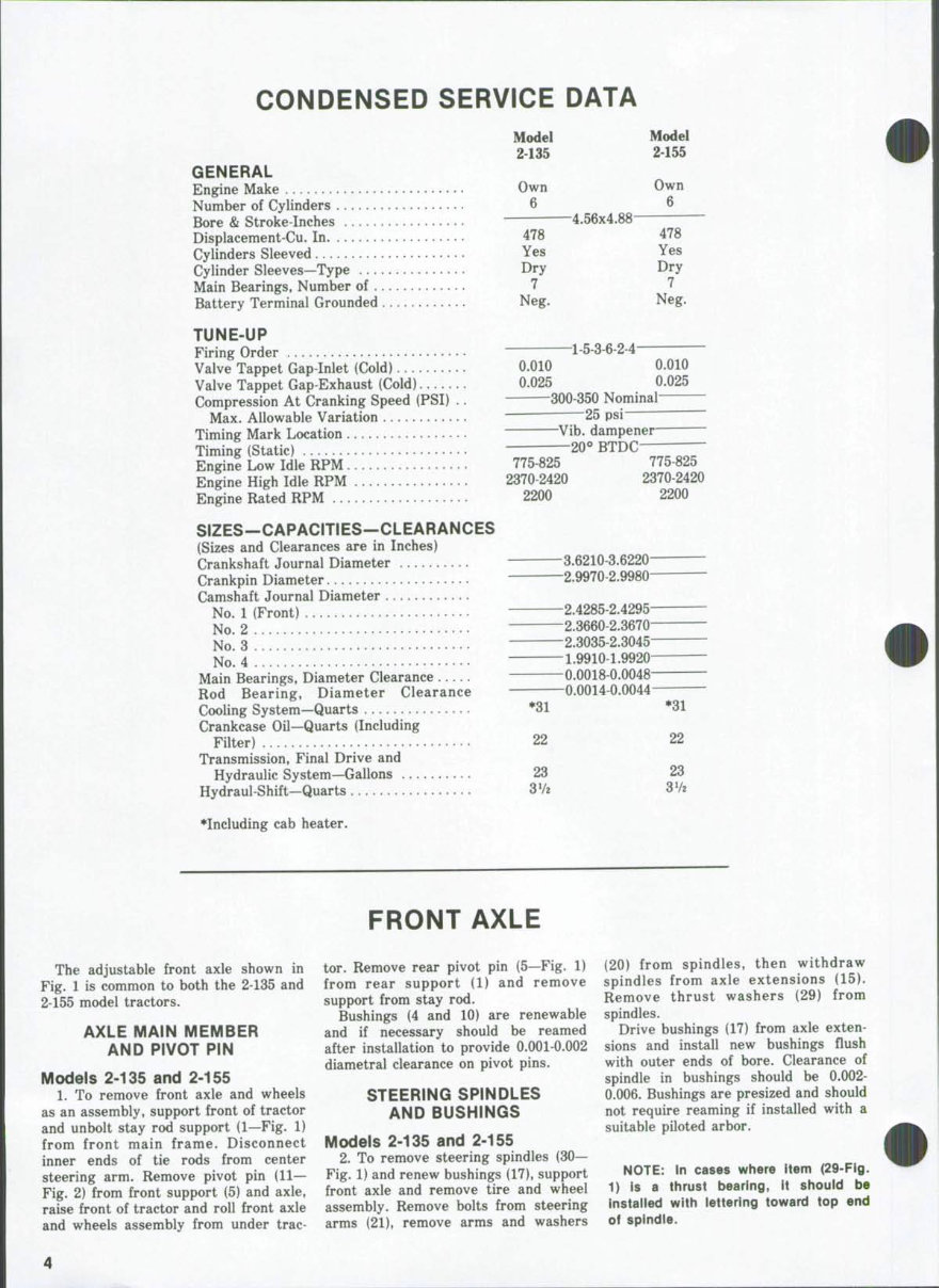
CONDENSED SERVICE DATA
Model
2-135
Model
2-155
Own
6
478
Yes
Dry
7
Neg.
4.56x4.00
-1-5-3-6-24-
Own
6
478
Yes
Dry
7
Neg.
GENERAL
Engine Make
Number of Cylinders
Bore & Stroke-Inches
Displacement-Cu. In.
Cylinders Sleeved
Cylinder Sleeves—Type
Main Bearings, Number of
Battery Terminal Grounded
TUNE-UP
Firing Order
Valve Tappet Gap-Inlet (Cold) 0.010 0.010
Valve Tappet Gap-Exhaust (Cold) 0.025 0.025
Compression At Cranking Speed (PSI) .. 300-350 Nominal
Max. Allowable Variation 25 psi
Timing Mark Location Vib. dampener
Timing (Static) 20° BTDC
Engine Low Idle RPM 775-825
Engine High Idle RPM 2370-2420
Engine Rated RPM 2200
SIZES—CAPACITIES—CLEARANCES
(Sizes and Clearances are in Inches)
Crankshaft Journal Diameter 3.6210-3.6220-
Crankpin Diameter 2.9970-2.9980"
Camshaft Journal Diameter
No. 1 (Front) 2.4285-2.4295
No 2 2.3660-2.3670
No 3 2.3035-2.3045
No! 4 1.9910-1.9920
Main Bearings, Diameter Clearance 0.0018-0.0048
Rod Bearing, Diameter Clearance 0.0014-0.0044
Cooling System—Quarts *31
Crankcase Oil—Quarts (Including
Filter) 22
Transmission, Final Drive and
Hydraulic System—Gallons 23
Hydraul-Shift—Quarts 37?
•Including cab heater.
775-825
2370-2420
2200
*31
22
23
3V2
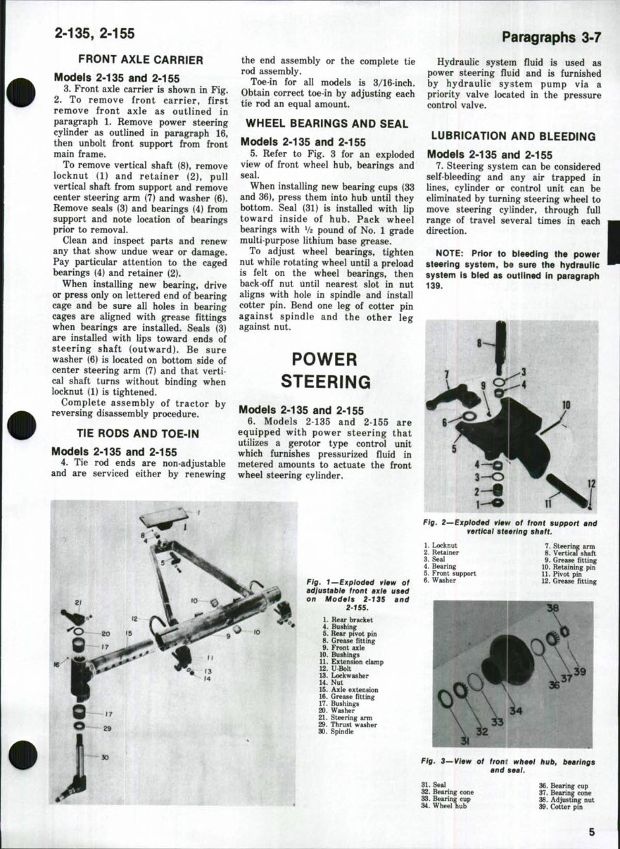
FRONT AXLE
The adjustable front axle shown in
Fig. 1 is common to both the 2-135 and
2-155 model tractors.
AXLE MAIN MEMBER
AND PIVOT PIN
Models 2-135 and 2-155
1. To remove front axle and wheels
as an assembly, support front of tractor
and unbolt stay rod support (1—Fig. 1)
from front main frame. Disconnect
inner ends of tie rods from center
steering arm. Remove pivot pin (11—
Fig. 2) from front support (5) and axle,
raise front of tractor and roll front axle
and wheels assembly from under trac-
tor. Remove rear pivot pin (5—Fig. 1)
from rear support (1) and remove
support from stay rod.
Bushings (4 and 10) are renewable
and if necessary should be reamed
after installation to provide 0.001-0.002
diametral clearance on pivot pins.
STEERING SPINDLES
AND BUSHINGS
Models 2-135 and 2-155
2. To remove steering spindles (30—
Fig. 1) and renew bushings (17), support
front axle and remove tire and wheel
assembly. Remove bolts from steering
arms (21), remove arms and washers
(20) from spindles, then withdraw
spindles from axle extensions (15).
Remove thrust washers (29) from
spindles.
Drive bushings (17) from axle exten-
sions and install new bushings flush
witb outer ends of bore. Clearance of
spindle in bushings should be 0.002-
0.006. Bushings are presized and should
not require reaming if installed with a
suitable piloted arbor.
NOTE: In cases where item (29-Fig.
1) is a thrust bearing, it should be
installed with lettering toward top end
of spindle.
2-135, 2-155
FRONT AXLE CARRIER
Models 2-135 and 2-155
3. Front axle carrier is shown in Fig.
2. To remove front carrier, first
remove front axle as outlined in
paragraph 1, Remove power steering
cylinder as outlined in paragraph 16,
then unbolt front support from front
main frame.
To remove vertical shaft (8), remove
locknut (1) and retainer (2), pull
vertical shaft from support and remove
center steering arm (7) and washer (6).
Remove seals (3) and bearings (4) from
support and note location of bearings
prior to removal
Clean and inspect parts and renew
any that show undue wear or damage.
Pay particular attention to the caged
bearings (4) and retainer (2).
When installing new bearing, drive
or press only on lettered end of bearing
cage and be sure all holes in bearing
cages are aligned with grease fittings
when bearings are installed. Seals (3)
are installed with lips toward ends of
steering shaft (outward). Be sure
washer (6) is located on bottom side of
center steering arm (7) and that verti-
cal shaft turns without binding when
locknut (1) is tightened.
Complete assembly of tractor by
reversing disassembly procedure.
TIE RODS AND TOE-IN
Models 2-135 and 2-155
4. Tie rod ends are non-adjustable
and are serviced either by renewing
the end assembly or the complete tie
rod assembly.
Toe-in for all models is 3/16-inch.
Obtain correct toe-in by adjusting each
tie rod an equal amount.
WHEEL BEARINGS AND SEAL
Models 2-135 and 2-155
5. Refer to Fig. 3 for an exploded
view of front wheel hub, bearings and
seal.
When installing new bearing cups (33
and 36), press them into hub until they
bottom. Seal (31) is installed with lip
toward inside of hub. Pack wheel
bearings with V2 pound of No. 1 grade
multi-purpose lithium base grease.
To adjust wheel bearings, tighten
nut while rotating wheel until a preload
is felt on the wheel bearings, then
back-off nut Until nearest slot in nut
aligns with hole in spindle and install
cotter pin. Bend one leg of cotter pin
against spindle and the other leg
against nut.
POWER
STEERING
Models 2-135 and 2-155
6. Models 2-135 and 2-155 are
equipped with power steering that
utilizes a gerotor type control unit
which furnishes pressurized fluid in
metered amounts to actuate the front
wheel steering cylinder.
Fig, 1—Exploded view of
adjustable front axle used
on Models 2-135 and
2-155.
I. Rear bracket
4. Bushing
5. Rear pivot pin
8. Grease fitting
9. Front axle
10. Bushings
11. Extension clamp
12. U Bolt
13. Lock washer
14. Nut
15. Axle extension
16. Grease fitting
17. Bushings
20. Washer
21. Steering arm
29. Thrust washer
30. Spindle
Paragraphs 3-7
Hydraulic system fluid is used as
power steering fluid and is furnished
by hydraulic system pump via a
priority valve located in the pressure
control valve.
LUBRICATION AND BLEEDING
Models 2-135 and 2-155
7. Steering system can be considered
self-bleeding and any air trapped in
lines, cylinder or control unit can be
eliminated by turning steering wheel to
move steering cylinder, through full
range of travel several times in each
direction.
NOTE: Prior to bleeding the power
steering system, be sure the hydrauiic
system is bied as outlined in paragraph
139.
3-O
Fig, 2—Exploded vievf of front support and
vertical steering shaft.
1. Locknut 7. Steering arm
2. ReUiner 8. Vertical shaft
3. Seal 9. Grease fitting
4. Bearing 10. ReUining pin
5. Front support 11. Pivot pin
6. Washer 12. Grease fitting
Fig, 3—View of front wheel hub, bearings
and seal.
31. Seal
32. Bearing cone
33. Bearing cup
34. Wheel hub
36. Bearing cup
37. Bearing cone
38. Adjusting nut
39. Cotter pin
Paragraphs 8-11
WHITE
SYSTEM PRESSURE TEST
Models 2-135 and 2-155
8. Steering system operating pres-
sure should be 1775-1825 psi when
checked with engine running at approx-
imately 2000 rpm.
To check steering system pressure,
refer to paragraph 144 of HYDRAULIC
LIFT section of this manual.
PUMP
Models 2-135 and 2-155
9. The hydraulic lift system pump
also furnishes the pressurized oil for
operation of the power steering sys-
tem.
For information on the hydraulic lift
system pump, refer to paragraph 171.
CONTROL UNIT
Models 2-135 and 2-155
10. R&R CONTROL UNIT. Discon-
nect battery ground strap. Remove cap
from steering wheel, unscrew wheel
retaining nut and use a puller to
remove steering wheel. DO NOT ham-
mer on steering shaft. Remove both
lower instrument panel support side
filler plates, then disconnect light
switch, turn signal switch and differ-
ential lock toggle switch from lower
instrument panel. Unbolt and remove
lower instrument panel with grommet.
Tag the four control unit hoses to
facilitate reinstallation, then disconnect
hoses from control unit and immedi-
ately cap all openings. Remove the flat
headed carrier pivot screws and lift
unit from instrument panel support.
Reverse removal procedure to install
control unit assembly and bleed unit as
outlined in paragraph 7.
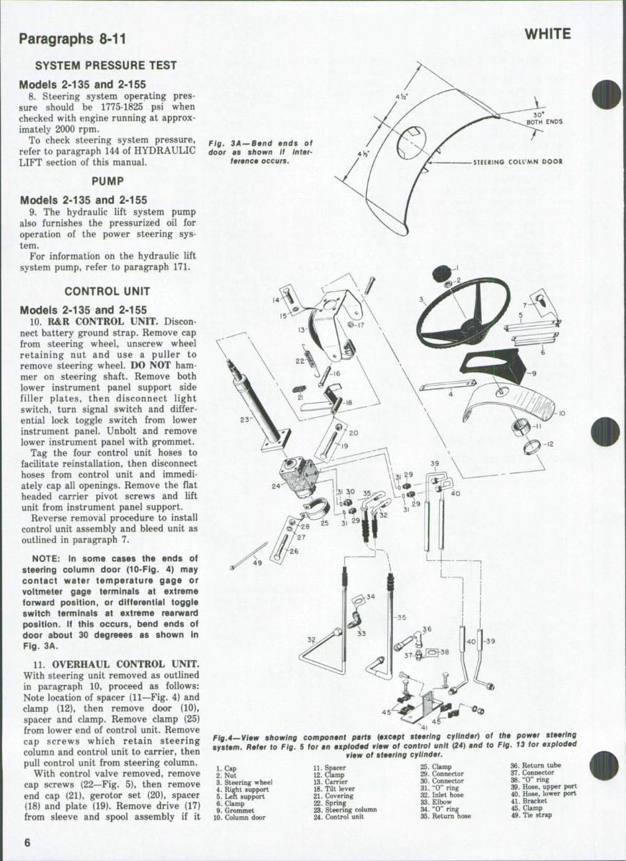
NOTE: In some cases the ends of
steering column door (10-Flg. 4) may
contact water temperature gage or
voltmeter gage terminals at extreme
forward position, or differential toggle
switch terminals at extreme rearward
position. If this occurs, bend ends of
door about 30 degreees as shown In
Fig. 3A.
11. OVERHAUL CONTROL UNIT.
With steering unit removed as outlined
in paragraph 10, proceed as follows:
Note location of spacer (11—Fig. 4) and
clamp (12), then remove door (10).
spacer and clamp. Remove clamp (25)
from lower end of control unit. Remove
cap screws which retain steering
column and control unit to carrier, then
pull control unit from steering column.
With control valve removed, remove
cap screws (22—Fig. 5), then remove
end cap (21). gerotor set (20). spacer
(18) and plate (19). Remove drive (17)
from sleeve and spool assembly if it
Fig. 3A — Bend ends of
door as shown if inter-
ference occurs. STEERING COIVMN DOOR
. 45
41
Fig,4—View showing component parts {axcapt stearing cylindar) of
system. Rafar to Fig. 5 for an axplodad view of control unit {24) and to
vlaw of staering cylinder.
1. Cap
2. Nut
3. Steering wheel
4. Right support
5. Lett support
6. Clamp
9. Grommet
10. Column door
11. Spacer
12. Clamp
13. Carrier
18. TUt lever
21. Covering
22. Spring
23. Steering column
24. Control unit
25. Clamp
29. Connector
30. Connector
31. "0" ring
32. Inlet hose
33. Elbow
34. "0" ring
35. Return hose
the power steering
Fig, 13 for exploded
36. Return tube
37. Connector
38. "0" ring
39. Hose, upper port
40. Hose, lower port
41. Bracket
45. Clamp
49. Tie strap
6
2-135, 2-155
2Z
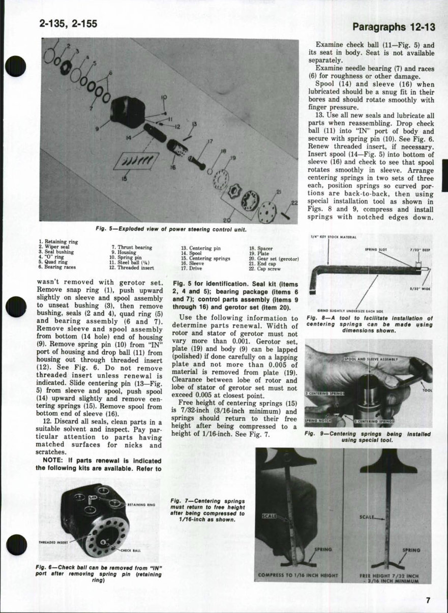
Fig, S—Exploded view of power steering control unit
1. Retaining rin?
2. Wiper seal
3. Seal bushing
4. "0" ring
5. Quad ring
6. Bearing races
7. Thrust bearing
9. Housing
10. Spring pin
11. Steet ball(V4)
12. Threaded insert
13. Centering pin
14. Spool
15. Centeri
16. Sleeve
17. Drive
ng springs
18. Spacer
19. Plate
20. Gear set {gerotor)
21. End cap
22. Cap screw
wasn't removed with gerotor set.
Remove snap ring (1), push upward
slightly on sleeve and spool assembly
to unseat bushing (3), then remove
bushing, seals (2 and 4), quad ring (5)
and bearing assembly (6 and 7).
Remove sleeve and spool assembly
from bottom (14 hole) end of housing
(9). Remove spring pin (10) from "IN"
port of housing and drop ball (11) from
housing out through threaded insert
(12). See Fig. 6. Do not remove
threaded insert unless renewal is
indicated. Slide centering pin (13—Fig.
5) from sleeve and spool, push spool
(14) upward slightly and remove cen-
tering springs (15). Remove spool from
bottom end of sleeve (16).
12. Discard all seals, clean parts in a
suitable solvent and inspect. Pay par-
ticular attention to parts having
matched surfaces for nicks and
scratches.
NOTE: If parts renewal is indicated
the foUowing kits are availabie. Refer to
Fig. 5 for identification. Seal kit (items
2. 4 and 5); bearing package (items 6
and 7); control parts assembly (items 9
through 16) and gerotor set (item 20).
Use the following information to
determine parts renewal. Width of
rotor and stator of gerotor must not
vary more than 0.001. Gerotor set.
plate (19) and body (9) can be lapped
(polished) if done carefully on a lapping
plate and not more than 0.005 of
material is removed from plate (19).
Clearance between lobe of rotor and
lobe of stator of gerotor set must not
exceed 0.005 at closest point.
Free height of centering springs (15)
is 7/32-inch (3/16-inch minimum) and
springs should return to their free
height after being compressed to a
height of 1/16-inch. See Fig. 7.
Paragraphs 12-13
Examine check ball (11—Fig. 5) and
its seat in body. Seat is not available
separately.
Examine needle bearing (7) and races
(6) for roughness OP other damage.
Spool (14) and sleeve (16) when
lubricated should be a snug fit in their
bores and should rotate smoothly with
finger pressure.
13. Use all new seals and lubricate all
parts when reassembling. Drop check
ball (11) into "IN" port of body and
secure with spring pin (10). See Fig. 6.
Renew threaded insert, if necessary.
Insert spool (14—Fig. 5) into bottom of
sleeve (16) and check to see that spool
rotates smoothly in sleeve. Arrange
centering springs in two sets of three
each, position springs so curved por-
tions are back-to-back, then using
special installation tool as shown in
Figs. 8 and 9, compress and install
springs with notched edges down.
1/4" KiY STOCK MAflKtAL
• HMD aiCHTlT UNDf'l»ZI lACH
Fig, 8—A tool to faciiitate installation of
centering springs can be made using
shown.
Fig. 9—Centering springs being
using special tool.
Installed
tlTAININO UMO
Fig. 7—Centering springs
must return to free height
after being compressed to
T/T6-/ncA as shown.
Fig. $^Check ball can be removed from "IH"
port after removing spring pin {retaining
ring)
TO 1/16 INCH HEIGHT
SC/iLE
FREE HEIGHT 7/32 INCH
• 3/16 INCH MtNIMUM
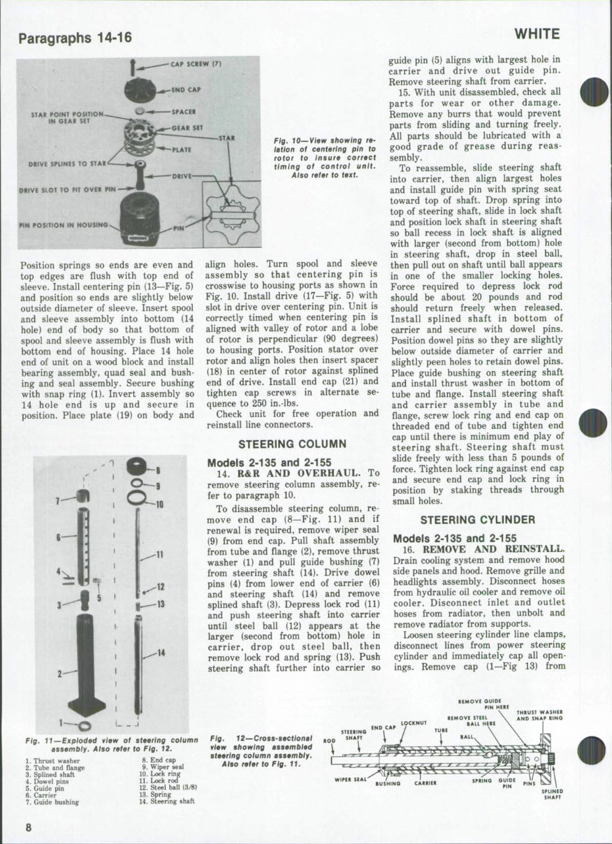
Paragraphs 14-16
f
STAR POINT POSITION
m a f AK SET
DItlVE SniNES TO STAR
&t)VE SLOT TO m OVER P%H
PtN POSITION IN HOUSING
Position springs so ends are even and
top edges are flush with top end of
sleeve. Install centering pin (13—Fig. 5)
and position so ends are slightly below
outside diameter of sleeve. Insert spool
and sleeve assembly into bottom (14
hole) end of body so that bottom of
spool and sleeve assembly is flush with
bottom end of housing. Place 14 hole
end of unit on a wood block and install
bearing assembly, quad seal and bush-
ing and seal assembly. Secure bushing
with snap ring (1). Invert assembly so
14 hole end is up and secure in
position. Place plate (19) on body and
Fig. 10—Viaw showing ra-
lation of centering pin to
rotor to insure corract
timing of controi unit.
Aiso refer to taxt.
-12
align holes. Turn spool and sleeve
assembly so that centering pin is
crosswise to housing ports as shown in
Fig. 10. Install drive (17—Fig. 5) with
slot in drive over centering pin. Unit is
correctly timed when centering pin is
aligned with valley of rotor and a lobe
of rotor is perpendicular (90 degrees)
to housing ports. Position stator over
rotor and align holes then insert spacer
(18) in center of rotor against spiined
end of drive. Install end cap (21) and
tighten cap screws in alternate se-
quence to 250 in.-lbs.
Check unit for free operation and
reinstall line connectors.
STEERING COLUMN
Models 2-135 and 2-155
14. R&R AND OVERHAUL. To
remove steering column assembly, re-
fer to paragraph 10.
To disassemble steering column, re-
move end cap (8—Fig. 11) and if
renewal is required, remove wiper seal
(9) from end cap. Pull shaft assembly
from tube and flange (2), remove thrust
washer (1) and pull guide bushing (7)
from steering shaft (14). Drive dowel
pins (4) from lower end of carrier (6)
and steering shaft (14) and remove
spiined shaft (3). Depress lock rod (11)
and push steering shaft into carrier
until steel ball (12) appears at the
larger (second from bottom) hole in
carrier, drop out steel ball, then
remove lock rod and spring (13). Push
steering shaft further into carrier so
1. Thrust washer
2. Tube and flange
3. Spiined shaft
4. Dowel pins
5. Guide pin
6. Carrier
7. Guide bushing
8. End cap
9. Wiper seal
10. Lock ring
11. Lock ro<r
12. Steel ball (3/8)
13. Spring
14. Steering shaft
WHITE
guide pin (5) aligns with largest hole in
carrier and drive out guide pin.
Remove steering shaft from carrier.
15. With unit disassembled, check all
parts for wear or other damage.
Remove any burrs that would prevent
parts from sliding and turning freely.
All parts should be lubricated with a
good grade of grease during reas-
sembly.
To reassemble, slide steering shaft
into carrier, then align largest holes
and install guide pin with spring seat
toward top of shaft. Drop spring into
top of steering shaft, slide in lock shaft
and position lock shaft in steering shaft
so ball recess in lock shaft is aligned
with larger (second from bottom) hole
in steering shaft, drop in steel ball,
then pull out on shaft until ball appears
in one of the smaller locking holes.
Force required to depress lock rod
should be about 20 pounds and rod
should return freely when released.
Install spiined shaft in bottom of
carrier and secure with dowel pins.
Position dowel pins so they are slightly
below outside diameter of carrier and
slightly peen holes to retain dowel pins.
Place guide bushing on steering shaft
and install thrust washer in bottom of
tube and flange. Install steering shaft
and carrier assembly in tube and
flange, screw lock ring and end cap on
threaded end of tube and tighten end
cap until there is minimum end play of
steering shaft. Steering shaft must
slide freely with less than 5 pounds of
force. Tighten lock ring against end cap
and secure end cap and lock ring in
position by staking threads through
small holes.
STEERING CYLINDER
Models 2-135 and 2-155
16. REMOVE AND REINSTALL.
Drain cooling system and remove hood
side panels and hood. Remove grille and
headlights assembly. Disconnect hoses
from hydraulic oil cooler and remove oil
cooler. Disconnect inlet and outlet
hoses from radiator, then unbolt and
remove radiator from supports.
Loosen steering cylinder line clamps,
disconnect lines from power steering
cylinder and immediately cap all open-
ings. Remove cap (1—Fig 13) from
REMOVE GUIDE
HERE
THRUST WASHER
AND SNAP RING
Fig. 11—Exploded viaw of staaring column
assembly. Also refer to Fig, 12.
Fig. 12—CrosS'S»ctional
viaw showing assambtad
staaring column assambly.
Also rafar to Fig. 11.
2-135, 2-155
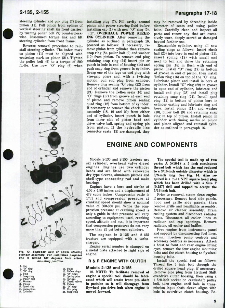
Paragraphs 17-18
steering cylinder and pry plug (7) from
pinion (11). Pull pinion from splines of
vertical steering shaft (in front carrier)
by turning puller bolt (9) counterclock-
wise. Disconnect torque link and lift
steering cylinder from front frame.
Reverse removal procedure to rein-
stall steering cylinder. The index mark
on pinion (11) must be aligned with
centering mark on piston (21). Tighten
the puller bolt (9) to a torque of 200
ft.-lbs. Use new "0" ring (6) when
Fig, 13—Exploded view of power steering
cylinder assembly. For illustrative purposes
unit is turned 180 degrees from actual
mounting position.
1. Cap
5. "O'^ ring
6. "0" ring
7. Plug
8. Snap ring
9. Puller bolt
10. Washer
11. Pinion
12. Quad ring
13. Connectors
14. CyUnder
15. Plugs
16. Teflon rings
17. "0" rings
18. Spring pins
19. Springs
20. Check valves
21. Piston
22. "0" ring
23. End plug
24. Snap ring
installing plug (7). Fill cavity around
pinion with power steering fluid before
installing cap (1) with new "0" ring (5).
17. OVERHAUL POWER STEER-
ING CYLINDER. After removing the
cylinder as outlined in paragraph 16,
proceed as follows: If necessary, re-
move pinion from cylinder then remove
snap ring (8), puller bolt (9) and washer
(10) from pinion. To remove end plug
retaining snap ring (24) insert pin or
punch in hole in end of housing (14) and
push snap ring from groove in cylinder.
Grasp one of the lugs on end plug with
vise-grip pliers and, with a twisting
motion, pull end plug from cylinder.
Remove plug sealing "0" ring (22) from
end of cylinder and remove the piston
(21). Remove the Teflon seals (16) and
"0" rings (17) from groove at each end
of piston and remove pinion sealing
quad ring (12) from bottom of cylinder.
If necessary to remove the check valve
assembly (18, 19 and 20) from either
end of cylinder, insert punch in hole
from inner side of piston head and
drive valve ball, spring and spring pin
from piston. If the hydraulic line
connector seats (13) are damaged, they
may be removed by threading inside
diameter of seats and using puller
bolts. Carefully clean and inspect all
parts and renew any that are exces-
sively worn, deeply scored or damaged
beyond further use.
Reassemble cylinder, using all new
sealing rings as follows: Insert check
ball (20) into bore in end of piston (21),
insert spring (19) with small end
next to ball and drive the retaining
spring pin (18) in flush with end of
piston. Install "0" ring (17) in bottom
of groove in end of piston, then install
Teflon ring (16) on top of the "0" ring.
Lubricate piston and install in bore of
cylinder. Install "0* ring (22) in groove
in open end of cylinder, lubricate and
install end plug (23)* and install plug
retaining snap ring (24). Install quad
ring (12) in bottom of pinion bore in
cylinder casting and lubricate ring and
bore. Install pinion (11), and washer
(10), puller bolt (9) and retaining snap
ring in top of pinion. Install pinion in
cylinder with timing marks on pinion
and piston aligned and reinstall cylin-
der as outlined in paragraph 16.
ENGINE AND COMPONENTS
Models 2435 and 2-155 tractors use
six cylinder, overhead valve diesel
engines. Engines use two cylinder
heads and are fitted with renewable
dry type sleeves, aluminum pistons and
shell-type connecting rod and main
bearings.
Engines have a bore and stroke of
4.56 X 4.88 inches and a displacement of
478 cubic inches. Compression ratio is
17:1 and compression pressure at
cranking speed should show a nominal
value of 300-350 psi. While the com-
pression pressure at cranking speed is
only a guide in that pressure will vary
according to equipment used, cranking
speed, altitude and etc., it is important
that compression pressures do not vary
more than 25 psi between cylinders.
The engines in 2-135 and 2-155
tractors are equipped with a turbo-
charger.
Engine serial number is stamped on
a metal plate attached to right side of
engine.
R & R ENGINE WITH CLUTCH
Models 2-135 and 2-155
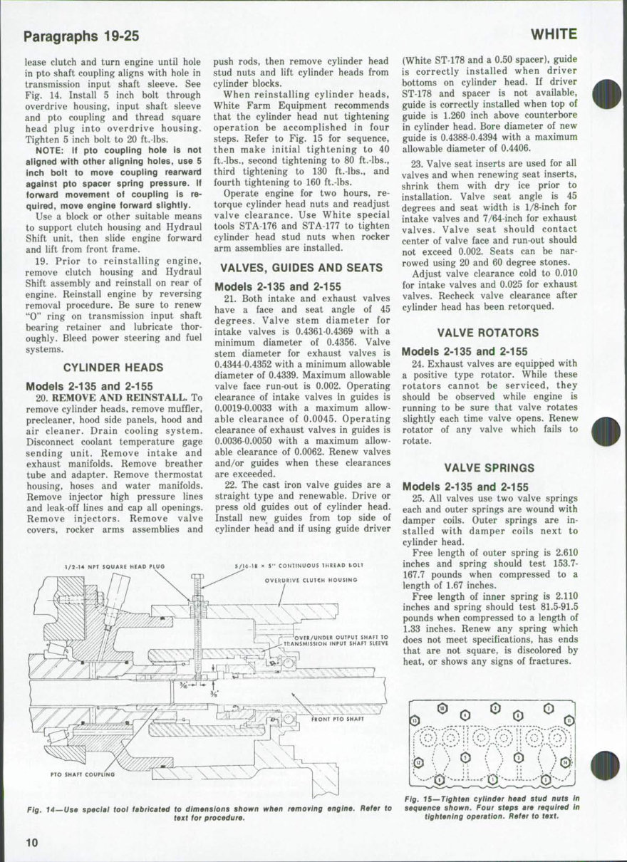
18. NOTE: To facilitate removal of
engine a special tool should be fabri-
cated which will retain front pto shaft
in position so it will disengage from
flywheel pto drive hub when engine is
moved forward.
The special tool is made up of two
parts: A 5/16-18 x 5 inch continuous
thread bolt which has the end reduced
to a 3/16-inch outside diameter which is
a/8-inch long. See Fig. 14. Also re-
quired is a 72-14 NPT square head plug
which has been di*iUed with a Size F
[0.257] drill and tupped to accept the
5/16-inch bolt.
Prior to removal, steam clean engine
if necessary. Remove hood side panels,
hood and grille side panels, then
remove grille and headlights assembly.
Remove air cleaner assembly. Drain
cooling system and disconnect radiator
hoses. Disconnect oil cooler lines at
radiator and cap openings. Remove
radiator, oil cooler and baffles.
Free engine from instrument panel
and support by disconnecting fuel lines,
wiring, injection pump controls and
accessory controls as necessary. Attach
a hoist to front and rear engine lifting
eyes, remove the four engine mounting
bolts and the clutch housing to flywheel
housing bolts.
Install the special tool as follows:
Thread the 5 inch. bolt through the
drilled square head plug, if necessary.
Remove pipe plug from Hydraul Shift
overdrive clutch housing, then using a
1 5/8-inch socket on crankshaft pulley
bolt, turn engine until hole in trans-
mission input shaft sleeve aligns with
hole in overdrive clutch housing. Re-
9
Paragraphs 19-25
lease clutch and turn engine until hole
in pto shaft coupling aligns with hole in
transmission input shaft sleeve. See
Fig. 14. Install 5 inch bolt through
overdrive housing, input shaft sleeve
and pto coupling and thread square
head plug into overdrive housing.
Tighten 5 inch bolt to 20 ft.-lbs.
NOTE: if pto coupiing hoie is not
aiigned with other aiigning hoies, use 5
inch boit to move coupiing rearward
against pto spacer spring pressure, if
forward movement of coupiing is re-
quired, move engine forward siightiy.
Use a block or other suitable means
to support clutch housing and Hydraul
Shift unit, then slide engine forward
and lift from front frame.
19. Prior to reinstalling engine,
remove clutch housing and Hydraul
Shift assembly and reinstall on rear of
engine. Reinstall engine by reversing
removal procedure. Be sure to renew
"0" ring on transmission input shaft
bearing retainer and lubricate thor-
oughly. Bleed power steering and fuel
systems.
CYLINDER HEADS
Models 2-135 and 2-155
20. REMOVE AND REINSTALL. To
remove cylinder heads, remove muffler,
precleaner, hood side panels, hood and
air cleaner. Drain cooling system.
Disconnect coolant temperature gage
sending unit. Remove intake and
exhaust manifolds. Remove breather
tube and adapter. Remove thermostat
housing, hoses and water manifolds.
Remove injector high pressure lines
and leak-off lines and cap all openings.
Remove injectors. Remove valve
covers, rocker arms assemblies and
1/2-M NPT SQUARE HEAD PLUG
push rods, then remove cylinder head
stud nuts and lift cylinder heads from
cylinder blocks.
When reinstalling cylinder heads.
White Farm Equipment recommends
that the cylinder head nut tightening
operation be accomplished in four
steps. Refer to Fig. 15 for sequence,
then make initial tightening to 40
ft.-lbs., second tightening to 80 ft.-lbs.,
third tightening to 130 ft.-lbs., and
fourth tightening to 160 ft.-lbs.
Operate engine for two hours, re-
torque cylinder head nuts and readjust
valve clearance. Use White special
tools STA-176 and STA-177 to tighten
cylinder head stud nuts when rocker
arm assemblies are installed.
VALVES, GUIDES AND SEATS
Models 2-135 and 2-155
21. Both intake and exhaust valves
have a face and seat angle of 45
degrees. Valve stem diameter for
intake valves is 0.4361-0.4369 with a
minimum diameter of 0.4356. Valve
stem diameter for exhaust valves is
0.4344-0.4352 with a minimum allowable
diameter of 0.4339. Maximum allowable
valve face run-out is 0.002. Operating
clearance of intake valves in guides is
0.0019-0.0033 with a maximum allow-
able clearance of 0.0045. Operating
clearance of exhaust valves in guides is
0.0036-0.0050 with a maximum allow-
able clearance of 0.0062. Renew valves
and/or guides when these clearances
are exceeded.
22. The cast iron valve guides are a
straight type and renewable. Drive or
press old guides out of cylinder head.
Install new guides from top side of
cylinder head and if using guide driver
5/16-18 ^ 5" CONTINUOUS 1HREAD t>OlT
OVEfcURIVE CLUTCH HOUSING
' "' /^- -'OVER/UNDER OUTPUT SHAfT TO
|M-TRANSMISSION INPUT SHAFT SIECVE
WHITE
(White ST-178 and a 0.50 spacer), guide
is correctly installed when driver
bottoms on cylinder head. If driver
ST-178 and spacer is not available,
guide is correctly installed when top of
guide is 1.260 inch above counterbore
in cylinder head. Bore diameter of new
guide is 0.4388-0.4394 with a maximum
allowable diameter of 0.4406.
23. Valve seat inserts are used for all
valves and when renewing seat inserts,
shrink them with dry ice prior to
installation. Valve seat angle is 45
degrees and seat width is 1/8-inch for
intake valves and 7/64-inch for exhaust
valves. Valve seat should contact
center of valve face and run-out should
not exceed 0.002. Seats can be nar-
rowed using 20 and 60 degree stones.
Adjust valve clearance cold to 0.010
for intake valves and 0.025 for exhaust
valves. Recheck valve clearance after
cylinder head has been retorqued.
VALVE ROTATORS
Models 2-135 and 2-155
24. Exhaust valves are equipped with
a positive type rotator. While these
rotators cannot be serviced, they
should be observed while engine is
running to be sure that valve rotates
slightly each time valve opens. Renew
rotator of any valve which fails to
rotate.
VALVE SPRINGS
Models 2-135 and 2-155
25. All valves use two valve springs
each and outer springs are wound with
damper coils. Outer springs are in-
stalled with damper coils next to
cylinder head.
Free length of outer spring is 2.610
inches and spring should test 153.7-
167.7 pounds when compressed to a
length of 1.67 inches.
Free length of inner spring is 2.110
inches and spring should test 81.5-91.5
pounds when compressed to a length of
1.33 inches. Renew any spring which
does not meet specifications, has ends
that are not square, is discolored by
heat, or shows any signs of fractures.
PTO SHAFT COUPIING
4—Use special tool fabricated to dimensions shown when removing angina. Rafer to
taxt for procadura.
Fig. IS—Tighten cylinder head stud nuts In
sequence shown. Four steps are required In
tightening operation. Refer to text.
10
2-135, 2-155
Paragraphs 26-31
VALVE LIFTERS
(CAM FOLLOWERS)
Models 2-135 and 2-155
26. The straight type valve lifters
operate directly in machined bores in
the cylinder block. Valve lifters are
supplied only in standard size of 1.2475-
1.2480 and should have an -operating
clearance of 0.0033-0.0043 in their
bores.
Renew valve lifters if their diameter
is less then 1.2425. If diametral clear-
ance with new lifter in bore exceeds
0.007, renew cylinder block.
Valve lifters can be removed after
rocker arm assemblies, push rods and
engine side covert are removed.
VALVE ROCKER ARMS
AND SHAFTS
Models 2-135 and 2-155
27. To remove rocker arms, remove
muffler, precleaner, hood sides and
hood. Remove air cleaner assembly.
Remove adapter and breather tube.
Remove rocker arm covers, then unbolt
and remove rocker arms assemblies.
Lift out push rods and inspect.
To disassemble rocker arms assem-
blies, remove snap rings and washers
from ends of shafts, then remove pins
from ends of shafts and slide rocker
arms, springs and supports from shaft.
Remove plugs from ends of shaft if
they show signs of leakage.
Rocker shaft diameter is 0.9998-1.0005
with a reject diameter of 0.9978. Inside
bore of rocker arm is 1.0007-1.0038 and
should have an operating clearance of
0.0002-0.004 on shaft. If rocker arm
operating clearance exceeds 0.005,
renew rocker arm and/or shaft as
rocker arm bushings are not available
separately. Rocker arm contact radius
can be refaced providing the original
radius is maintained and kept parallel
with the rocker arm shaft. Shaft
springs have a free length of 3.500
inches and should exert 7.8-9.8 lbs.
when compressed to a length of 2.00
inches.
VALVE TIMING
Models 2-135 and 2-155
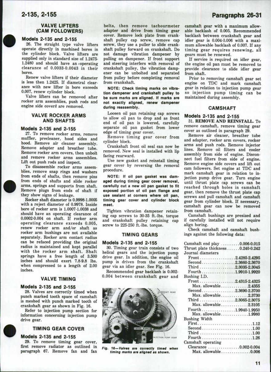
28. Valves are correctly timed when
punch marked tooth space of camshaft
is meshed with punch marked tooth of
crankshaft gear as shown in Fig. 16.
Refer to injection pump section for
information concerning injection pump
drive gear.
TIMING GEAR COVER
Models 2-135 and 2-155
29. To remove timing gear cover,
first remove radiator as outlined in
paragraph 67. Remove fan and fan
belts, then remove tachourmeter
adapter and drive from timing gear
cover. Remove lock plate from crank-
shaft pulley cap screw, remove cap
screw, they use a puller to slide crank-
shaft pulley forward on crankshaft. Do
not damage vibration dampener by
pulling on dampener. If front support
and steering interfers with removal of
crankshaft pulley, the vibration damp-
ener can be unbolted and separated
from pulley before completing removal
from crankshaft.
NOTE: Check timing marks on vibra-
tion dampener and crankshaft puiley to
be sure marks are aligned, if marks are
not exactly aligned, renew dampener
during reassembly.
Loosen oil pan retaining cap screws
to allow oil pan to drop and as front
end of oil pan is lowered, carefully
separate oil pan gasket from lower
edge of timing gear cover.
Remove timing gear cover from
cylinder block.
Crankshaft front oil seal can now be
removed. New seal is installed with lip
facing rearward.
Use new gasket and reinstall timing
gear cover by reversing the removal
procedure.
NOTE: If oil pan gasket was dam-
aged during timing gear cover removal,
carefully cut a new oil pan gasket to fit
exposed portion of oii pan flange and
use sealant at comers where oil pan,
timing gear cover and cyiinder block
meet.
Tighten vibration dampener retain-
ing cap screws to 30-35 ft.-lbs. torque
and crankshaft pulley retaining cap
screw to 225-250 ft.-lbs. torque.
TIMING GEARS
Models 2-135 and 2-155
30. Timing gear train consists of two
helical gears and the injection pump
drive gear. In addition, the engine oil
pump is driven from the crankshaft
gear via an idler gear. See Fig. 16.
Recommended gear backlash is 0.002-
0.004 between crankshaft gear and
\
Fig. IS—Valves are correctly ffm«d when
timing marks are aligned as shown.
camshaft gear with a maximum allow-
able backlash of 0.005. Recommended
backlash between crankshaft gear and
idler gear is 0.004-0.006 with a maxi-
mum allowable backlash of 0.007. If any
timing gear requires renewing, all
gears must be renewed.
If service is required on idler gear,
the engine oil pan must be removed to
provide clearance to slide idler gear
from shaft.
Prior to removing camshaft gear set
engine on TDC and mark camshaft
gear in relation to injection pump gear
so injection pump timing can be
maintained during assembly.
CAMSHAFT
Models 2-135 and 2-155
31. REMOVE AND REINSTALL. To
remove camshaft, remove timing gear
cover as outlined in paragraph 29.
Remove air cleaner, breather tube
and adapter, rocker arm covers, rocker
arms and push rods. Remove injector
lines. Remove oil filters and cooler
assembly from side of engine. Discon-
nect fuel filters from side of engine.
Remove engine side covers and lift out
cam followers. Set engine at TDC and
mark camshaft gear in relation to in-
jection pump drive gear. Turn engine
until thrust plate <:^p screws can be
reached through holes in camshaft
gear, then remove the thrust plate cap
screws and pull camshaft and camshaft
gear from cylinder block. If necessary,
camshaft gear can now be removed
from camshaft.
Camshaft bushings are presized and
if carefully installed will not require
align boring.
Check camshaft and camshaft bush-
ings against the following data:
Camshaft end play 0.006-0.015
Thrust plate thickness 0.240-0.242
Journal diameters
Front 2.4285-2.4295
Second 2.3660-2.3670
Third 2.3035-2.3045
Fourth 1.9910-1.9920
Bushing I.D.
Front 2.4315-2.4325
Max. allowable 2.4355
Second 2.3690-2.3700
Max. allowable 2.3730
Third 2.3065-2.3075
Max. allowable 2.3105
Fourth 1.9940-1.9950
Max. allowable 1.9980
Bushing Width
First 1.12
Second 1.00
Third .1.00
Fourth 1.26
Camshaft operating
Clearance 0.002-0.004
Max. allowable 0.006
11
You're Reading a Preview
What's Included?
Fast Download Speeds
Online & Offline Access
Access PDF Contents & Bookmarks
Full Search Facility
Print one or all pages of your manual
$41.99
Viewed 69 Times Today


Secure transaction
What's Included?
Fast Download Speeds
Online & Offline Access
Access PDF Contents & Bookmarks
Full Search Facility
Print one or all pages of your manual
$41.99
Thank you for considering this comprehensive Service Repair Workshop Manual for the White 2-135 & 2-155 Tractors.
This manual is an invaluable resource, covering every Service & Repair Procedure necessary for professional mechanics and DIY enthusiasts alike.
With easy-to-follow step-by-step instructions and detailed pictures, this manual empowers you to save significant costs by performing your own repairs.
Upon purchase, this manual becomes your permanent asset, allowing you to print specific pages, chapters, or the entire document. It is also compatible with tablets and smartphones for convenient access.
MODELS COVERED:
- All Models/Engines/Trim/Transmissions Types Are Covered
CONTENTS:
- This high-quality Service Repair Workshop Manual encompasses all repair procedures from A to Z, ensuring that every repair and service procedure is comprehensively addressed.
COMPUTER REQUIREMENTS:
- This downloadable Manual is compatible with all PC & MAC Computers, tablets, and mobile phones. It only requires adobe reader, which is typically pre-installed on most computers or can be downloaded for free.
INSTANT DELIVERY:
- Upon payment confirmation via Visa, MasterCard, or PayPal, the manual will be instantly emailed to the address provided during checkout.
Customer Satisfaction Guaranteed.


