SAME Golden 75 Compatto Factory Service & Work Shop Manual
What's Included?
Lifetime Access
Fast Download Speeds
Online & Offline Access
Access PDF Contents & Bookmarks
Full Search Facility
Print one or all pages of your manual
introduction This publication is intended for the trained technician who must operate on our tractors. It contains all general information relating to our tractor range, and in particular it highlights the inspection, overhauling and adjustment procedures as well as the main instructions for dismantling and reassembling operations. The workshop manual is a natural summary for the mechanic who has attended the vocational training and specializa- tion courses, which are held every year at our Service School, to permit him to perform a precise and qualified work on tractor. Its contents are therefore an exhaustive reference book for the experienced mechanic who desires to refresh his me- mory on the sequence of the operations to be done. It is then good practice for every authorized dealer mechanic to have at his disposal this publication, so that it may be consulted quickly when necessary. We wish to thank in advance for the cooperation all thos people, who will let us have their suggestions in order to make this publication more complete. 1 GOLDEN 60 GOLDEN 65 GOLDEN 75 GOLDEN 85 Compatto GOLDEN 60 GOLDEN 75 “V” WORKSHOP MANUAL Seat and headquarters V.le Ing. F. Cassani, 15 24047 Treviglio (BG) Tel. 0363/4211 Telex: 311472 Samtra I
List of contents Tractor configurations GOLDEN 60 - 65 - 75 - 85 .................................................................................................... 6 Dimensions and weights...........................................................................................................................................7 Prescribed lubricants and capacities ........................................................................................................................ 9 Conversion tables ...................................................................................................................................................10 Parts .......................................................................................................................................................................11 1 - ENGINE General characteristics ...........................................................................................................................................20 Timing specifications .............................................................................................................................................. 21 Lubrication system - specifications .........................................................................................................................22 Fuel supply system - specifications ........................................................................................................................ 23 Turbocharger - specifications .................................................................................................................................24 Cooling system .......................................................................................................................................................25 Adjusting backlash between the gear teeth of the auxiliary engine drive ............................................................... 27 Support for hydraulic pumps or air compressor located between engine block and timing cover .......................... 27 Timing idler gea ...................................................................................................................................................... 29 Cylinders.................................................................................................................................................................30 Main bearings .........................................................................................................................................................33 Crankshaft .............................................................................................................................................................. 35 Pistons.................................................................................................................................................................... 39 Piston rings .............................................................................................................................................................39 Counterweights for 4-cylinder engines ...................................................................................................................44 Engine flywheel ...................................................................................................................................................... 45 Checking camshaft .................................................................................................................................................48 Checking camshaft bushings.................................................................................................................................. 48 Checking timing gear .............................................................................................................................................. 48 Cylinder heads - valves - valve rockers.................................................................................................................. 49 Cleaning cylinder heads .........................................................................................................................................50 Checking engine compression ...............................................................................................................................53 Oil pump ................................................................................................................................................................ 54 Checking pressure relief valve ...............................................................................................................................54 Fitting shims between engine oil pan and front support ......................................................................................... 55 Fuel injection nozzles .............................................................................................................................................56 Mechanical-type engine governor ...................................................................................................................... 58 Mounting governor weights ...................................................................................................................................59 Calibrating engine governor ...................................................................................................................................61 Engine governor control assembly .........................................................................................................................64 Installing and checking actuator .............................................................................................................................69 Fuel injection pumps...............................................................................................................................................76 Injection pump control system ................................................................................................................................ 76 Installing injection pump control bar guide supports .............................................................................................. 76 Engine timing.......................................................................................................................................................... 77 Positioning the pumps ............................................................................................................................................ 80 Fuel filter .................................................................................................................................................................83 Draining water from fuel filter.................................................................................................................................. 83 Turbocharging Golden 65 - 85...............................................................................................................................88 Tightening torques.................................................................................................................................................. 92 Instructions for engine assembly ............................................................................................................................ 94 2 - CLUTCH Gearshift clutch.....................................................................................................................................................110 Spring specifications to Belleville washer for the clutch engagement .................................................................. 110 Cecking clutch ...................................................................................................................................................... 114 Adjusting clutch control pedal ...............................................................................................................................114 Bleeding air from the hydraulic circuit ...................................................................................................................114 Stripping the slave cylinder ...................................................................................................................................115 Stripping the master cylinder ................................................................................................................................ 116 AGROSHIFT UNIT DETACH FROM THE GEAR BOX........................................................................................ 122 Assembly of AGROSHIFT unit .............................................................................................................................133 Re-assembly of the Agroshift unit......................................................................................................................... 135 Fitting the oil manifolds of the Agroshift unit ......................................................................................................... 138 Diagnosing malfunctions ...................................................................................................................................... 142 2
3 - TRANSMISSION General specifications .......................................................................................................................................... 143 Technical specifications ........................................................................................................................................ 143 Speed change configurations ...............................................................................................................................144 Range selector rods and forks..............................................................................................................................159 Removal and refitting ............................................................................................................................................ 161 Removal of the rear gearbox without removing the platform (tractors equipped with platform or cab only).........161 Dismantling the gearbox .......................................................................................................................................162 Separating the AGROSHIFT unit from the gearbox ............................................................................................. 162 Removal of the gear train positioned in the front gearbox ....................................................................................163 Disassembly of the inversor control rods and forks ..............................................................................................164 Examining parts removed .....................................................................................................................................168 Gearbox case .......................................................................................................................................................168 Shafts ...................................................................................................................................................................168 Gears.................................................................................................................................................................... 168 Synchronizers .......................................................................................................................................................168 Bearings ...............................................................................................................................................................168 Adjusting play of the gearbox shafts by means of the thrust plates on the mini/inversor shaft and the secondary shaft ......169 Warnigns related to assembly of the gears of the PTO unit, the range reduction unit and synchronised PTO shaft .............................................................................................................................................................173 Assembly of the PTO...........................................................................................................................................173 Installation of the range reduction unit, the gear for the front-wheel drive shaft and the parking brake discs ......173 Bevel drive adjustment (see figs. 1 and 3). ..........................................................................................................183 Servicing operations .............................................................................................................................................184 Tightening torques ................................................................................................................................................ 184 Rear power take-off .............................................................................................................................................. 185 PTO clutch ............................................................................................................................................................ 192 Technical specifications ........................................................................................................................................ 193 Clutch inspection .................................................................................................................................................. 195 Checking clutch hydraulic pressures ....................................................................................................................196 Checking the end-play of the front shaft of the PTO clutch ..................................................................................197 Renewal of the rear PTO clutch ...........................................................................................................................198 Main operations for removal of the rear PTO unit ................................................................................................199 Ooperations for removal of the rear PTO unit ......................................................................................................200 4 - AXLES Rear axle .............................................................................................................................................................. 205 Installing the rear half-shafts ...............................................................................................................................205 Removal and disassembly of the epicyclic reduction unit ......................................................................................... 208 Fitting lateral stub axles of the wheel ...................................................................................................................209 2WD extendible axle.............................................................................................................................................210 Removing the axle from the front support ............................................................................................................212 Wheel hub ............................................................................................................................................................ 214 Front-wheel drive .................................................................................................................................................. 217 Removal of the axle from the front carrier ............................................................................................................218 Epicyclic reduction unit .........................................................................................................................................221 Side hubs .............................................................................................................................................................. 223 Fitting the front axle studs .................................................................................................................................... 224 Axle shafts ............................................................................................................................................................ 224 Gears.................................................................................................................................................................... 224 Bearings ...............................................................................................................................................................224 Adjusting bevel gears ...........................................................................................................................................226 Adjustment of the internal control of the mechanical differential lock ..................................................................227 Installing the differential assembly into the drive axle ..........................................................................................227 Fitting the steering angle limiting bolts .................................................................................................................228 Diagnosing malfunctions ...................................................................................................................................... 230 5 - VEHICLE Brakes .................................................................................................................................................................. 231 General information .............................................................................................................................................. 231 Hydraulic pump.....................................................................................................................................................232 Assembly of brake master cylinder (see fig 5) ......................................................................................................234 Checking the front brake disks on 2WD and 4WD front axles and the rear brake disks. ..................................... 235 Adjusting service brake pedals .............................................................................................................................235 Correct installation of inspection cover for parking brake discs ............................................................................236 Checking parking brake pads ...............................................................................................................................236 Bleeding air from the brake hydraulic system....................................................................................................... 237 Diagnosing malfunctions ...................................................................................................................................... 242 Installing the lift and front cover plate of the gearbox ........................................................................................... 244 Lift mechanism .....................................................................................................................................................244 Checking the safety valves ...................................................................................................................................244 Adjusting the lift .................................................................................................................................................... 247 Sensing arm assembly .........................................................................................................................................256 3
Power-lift distributor valve spring setting specifications ....................................................................................... 257 Oil flow control valve spring.................................................................................................................................. 257 Ppilot valve spring ................................................................................................................................................ 257 Hydraulic distributor spring ...................................................................................................................................257 Nonreturn valve spring .........................................................................................................................................257 Valvematicspring .................................................................................................................................................. 257 Electronic lift .........................................................................................................................................................258 Control level or depth control knob (6) .................................................................................................................259 Mix position/draft control (3) .................................................................................................................................259 Lowering speed control knob (1) .......................................................................................................................... 260 Maximum lift height control knob (2) .....................................................................................................................260 Up/Down control switch (5) ...................................................................................................................................260 Up control .............................................................................................................................................................260 Control/Float mode ...............................................................................................................................................260 Lock/release .........................................................................................................................................................260 Lift status indicator light ........................................................................................................................................ 260 Remote pushbuttons for lift operation from ground .............................................................................................. 261 Calibration of the AUTOMATIC ............................................................................................................................ 264 Emergency manual lift control ...............................................................................................................................264 Precautions for electronic equipment ...................................................................................................................275 Checking the electronics system .......................................................................................................................... 275 Checking mechanical components .......................................................................................................................275 Front hydraulic lift .................................................................................................................................................276 Hydraulic accumulator and antishock valve for front lift ....................................................................................... 277 Front power take-off .............................................................................................................................................279 Checking the clutch .............................................................................................................................................. 280 Testing the pressure settings of the clutch control valve ..................................................................................... 280 Instructions for disengaging the drive to the front PTO ........................................................................................ 283 Fitting the "RING-FEEDER" rings ........................................................................................................................ 284 Diagnosing malfuntions ........................................................................................................................................ 288 6 - CONTROLS Hydrostatic steering.............................................................................................................................................. 289 Inspections and checks ........................................................................................................................................ 290 Steering pump ...................................................................................................................................................... 290 Directional control valve ...................................................................................................................................... 290 Check the setting of the pressure relief valve....................................................................................................... 290 Bleeding the hydraulic circuit ................................................................................................................................ 290 Assembly of orbital pump unit .............................................................................................................................. 290 Teering wheel shaft .............................................................................................................................................291 Steering cylinders .................................................................................................................................................291 Instructions for the hydrostatic steering distributor assembly ............................................................................... 293 Mechanical controls3.............................................................................................................................................. 00 Electro-hydraulic controls .....................................................................................................................................316 Front PTO clutch engagement control.................................................................................................................. 316 Rear PTO clutch engagement control .................................................................................................................. 316 Front-wheel drive engagement control .................................................................................................................316 Rear PTO engagement control .............................................................................................................................316 The PTO may only be engaged when the engine is running................................................................................ 316 Gearbox................................................................................................................................................................ 316 Front and rear lift .................................................................................................................................................. 316 Piston for hydraulic adjustment of stabilisers. ...................................................................................................... 331 Adjustment of front and rear differential lock control ........................................................................................... 332 7 - BODYWORK Platform ................................................................................................................................................................ 333 Cab air filter .......................................................................................................................................................... 337 Screen wash .........................................................................................................................................................337 Screen wipers (front and rear) .............................................................................................................................. 337 Remove cab. ........................................................................................................................................................ 338 Breakage of the top hood release cable ...............................................................................................................338 8 - SYSTEMS Ventilation .............................................................................................................................................................339 Heating System .................................................................................................................................................... 339 Operation and maintenance of the air-conditioning system ................................................................................. 344 Water dripping from the points at which condensate drain lines are connected to the conditioning unit ............. 345 Checking system .................................................................................................................................................. 347 System safety elements .......................................................................................................................................347 Temperature regulation ........................................................................................................................................ 347 Charging the system.............................................................................................................................................348 Filling the metering unit ........................................................................................................................................ 348 4
Refilling the system with oil ..................................................................................................................................348 Verifying operation of the system after recharging ............................................................................................... 350 Directions for tightening air conditioning system pipeline fittings. ........................................................................350 Hydraulic system .................................................................................................................................................. 354 Oil filters ................................................................................................................................................................ 356 Hydraulic pumps ...................................................................................................................................................356 Checking the relief valves of the hydraulic lift system ..........................................................................................356 Stripping the hydraulic pump ................................................................................................................................357 Auxiliary hydraulic spool valves ............................................................................................................................359 Conversion of auxiliary spool valves from double acting to single acting operation (see fig 5) ............................362 Trailer hydraulic braking system ...........................................................................................................................367 Trailer hydraulic braking distributor unit ................................................................................................................367 Use of the tractor with CUNA 341/01 hydraulic trailer braking ............................................................................. 369 Starting .................................................................................................................................................................370 Installing the hydraulic braking valve for trailers equipped with “safety brake” ..........................................................374 electrical system ...................................................................................................................................................377 General safety directions ...................................................................................................................................... 378 Jump start utilizing another battery.......................................................................................................................379 Heating system .....................................................................................................................................................381 Heating and conditioning system ..........................................................................................................................382 Starting system .....................................................................................................................................................382 Ignition key ...........................................................................................................................................................384 Ventilation control .................................................................................................................................................384 Push button control ...............................................................................................................................................384 Wiper switch .........................................................................................................................................................385 Work ligths ............................................................................................................................................................ 386 Beacon push button .............................................................................................................................................. 386 Relay .................................................................................................................................................................... 387 Electronic flasher unit ...........................................................................................................................................387 Switch controlling .................................................................................................................................................388 Switch for emergency brake .................................................................................................................................388 Fuse box ...............................................................................................................................................................389 Instrument panel with digital display .....................................................................................................................390 Operation of the broken belts alarm control unit ................................................................................................... 392 Engine stop operation with a type 2MH engine control unit ................................................................................. 394 Electrical wiring.....................................................................................................................................................396 9 - APPENDIX Engine electronic unit ................................................................................................................................................ I Power lift tester version .................................................................................................................................... XLVII 5
TRACTOR CONFIGURATIONS: - GOLDEN 60-65-75-85 Compatto - GOLDEN 60-75 ”V” GOLDEN 60-65-75-85 Compatto GOLDEN 60-75 ”V” 2WD WITH PLATFORMA 2WD WITH CAB 4RM WITH PLATFORM 4WD WITH CAB CAB - ventilation + heating - with ventilation + heating + air conditioning GEARBOX Fully synchronised: For tractors with driving position with footsteps only - 16 Forward + 8 Reverse: 4 speeds x 2 ranges + mini-reduction + shuttle - 24 Forward + 12 Reverse: 4 speeds x 3 ranges + mini-reduction + shuttle For tractors with driving position with plataform/cab only - 20 Forward 10 Reverse: 5 speeds x 2 ranges (L-V) + mini-reduction-shuttle - 30 Forward 15 Reverse: 5 speeds x 3 ranges (SR-L-V) + mini-reduction-shuttle - 45 Forward 45 Reverse: 5 speeds x 3 ranges (L-N-V)+ Reverser + version AGROSHIFT - - CONTROLS - electro-hydraulic Agroshift control with 2 pushbuttons located on gear lever - rear PTO clutch with electro-hydraulic control and mechanical speed selector - groundspeed PTO with mechanical engagement/disengagement control - front PTO with electrohydraulic control - 4WD with mechanical control or optional electro-hydraulic control - differential locks with electro-hydraulic control for tractors equipped with platform or cab - differential locks with mechanical control for tractors with footplates - with electronic engine throttle (for tractors equipped with electronic governor) MECHANICALLY OPERATED REAR POWER-LIFT - with supplementary rams - without supplementary rams ELECTRONIC REAR LIFT - with auxiliary rams - without auxiliary rams - with auxiliary control pushbuttons mounted on fender HYDRAULIC SYSTEM The hydraulic system is equipped with two pumps: Standard: - 11 cc pump with 27 l/min capacity. Supplies power steering, electro-hydraulic control unit and gearbox lubrication circuits. - 14 cc pump with 34 l/min capacity. Supplies auxiliary service control valves and hydraulic lift. Optional: - 11 cc pump with 27 l/min capacity. Supplies power steering, AGROSHIFT control unit, electro-hydraulic control unit and gearbox lubrication circuits. - 19 cc pump with 47 l/min capacity. Supplies the hydraulic trailer breaking control valve, auxiliary service control valves and hydraulic lift. MAIN EQUIPMENT - front PTO - Economy PTO - front lift - Electronic lift - Electronic engine governor - 3-point linkage with hydraulically adjustable right-hand lift rod and stabilisers - 4-way or 6-way control valves with “Flow Divider” 6
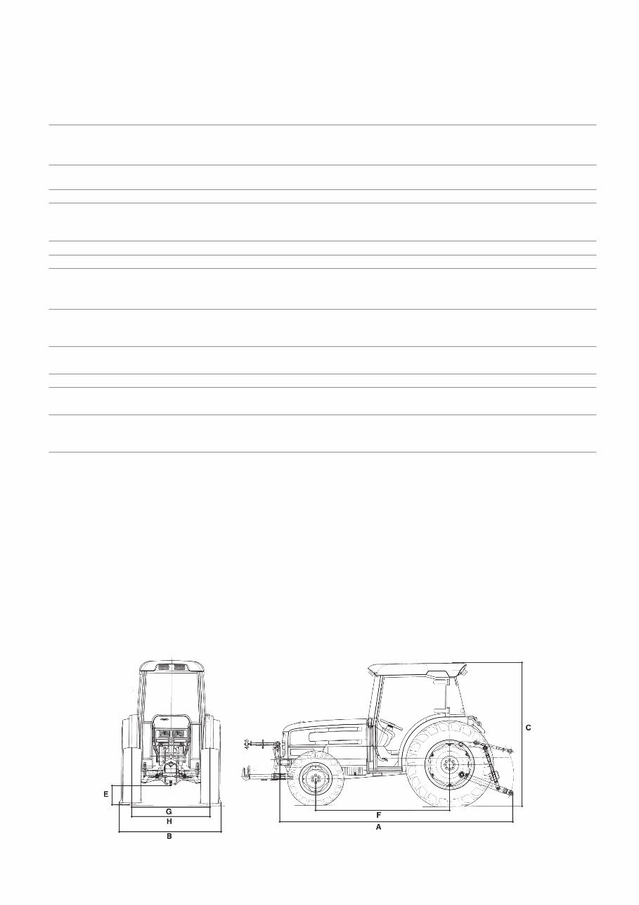
DIMENSIONS AND WEIGHTS GOLDEN 60- 65 GOLDEN 75-85 compatto compatto 2 WD 4 WD 2 WD 4 WD Max. length - without front linkage Without ballast (A) mm 3431 3431 3686 3686 With ballast (A) mm 3671 3671 3801 3801 - - with front and rear linkage Without ballast (A) mm 4036 4036 4201 4201 With ballast (A) mm 4136 4136 4301 4301 width min.-max (B) mm 1207/1507 1207/1507 1495/1691 1495/1691 Max. height. - at safety frame (C) mm 2210 2210 2210 2210 - at safety frame (C) mm 2220 2220 2170 2170 Ground clearance (E) mm 230 230 230 230 Wheel base (F) mm 1926 1926 2056 2056 Front track (G) standard mm 1050 1050 1050 1050 - minimum/maximum mm 954/1476 954/1476 1076/1476 1076/1476 Rear track ( H) standard mm 974 974 1076 1076 - minimum/maximum mm 974/1476 974/1476 1076/1476 1076/1476 Front tyres 7.50-16 320/70R20 7.50-16 320/70R20 Rear tyres 420/70R28 420/70R28 420/70R28 420/70R28 Operating weight (with front lift) - with driver platform Without ballast kg 2150 2180 2290 2370 With ballast kg 2255 2285 2395 2475 - with cab Without ballast kg 2300 2380 2455 2600 With ballast kg 2405 2485 2560 2705 Operating weight (with front lift) - with driver platform Without ballast kg - 2350 - 2540 With ballast kg - 2600 - 2790 - with cab Without ballast kg - 2500 - 2730 With ballast kg - 2750 - 2970 Min. turning radius (without brakes) mm 2905 3115 2905 3115 Weight of front ballast - front cast iron plates kg 140 (60x2) 140 (70x2) 140 (70x2) 140 (70x2) - monolithic block (4WD only) kg - 200 - 200 7
DIMENSIONS AND WEIGHTS GOLDEN 60V GOLDEN 75 V 2 WD 4 WD 2 WD 4 WD Tyres: - front 7.50-16 8.25/16 7.50/16 280/70R18 - rear 13.6R28 13.6R28 420/70R28 420/70R28 max. length - without front linkage (A) mm 3000 3000 3150 3150 min./max. width (B) mm 1063/1067 1063/1067 1063/1667 1063/1667 max. height - to hood (C) mm 1185 1185 1185 1185 - to steering wheel (D) mm 1236 1236 1236 1236 ground clearance (E) mm 225 225 225 225 wheelbase (F) mm 1926 1926 2056 2056 front track width (G) standard mm 853 863 853 863 minimum/maximum mm 803/1079 793/1089 803/1079 793/1089 rear track width (H) standard mm 902 902 902 902 minimum/maximum mm 822/1426 822/1426 822/1426 822/1426 front tyres 6.50-16 210/80R16 6.50-16 210/80R16 rear tyres 9.5R28 9.5R28 9.5R28 9.5R28 minimum turning radius (without brakes) mm 3060 3060 3230 3230 kerb weight (with driver platform) kg 1950 2100 1950 2100 weight of ballast - front cast iron plates kg 140 (70x2) 140 (70x2) 140 (70x2) 140 (70x2) - one-piece block (4WD only) kg - 200 - 200 8
PRESCRIBED LUBRICANTS AND FUELS (amounts in litres) Part to be supplied Amt Oil type Product Multigrade engine oil 6,7 ACEA E3-96 60-65HP API CF Engine SDFG OM-1991A AKROS TURBO MIL-L-2104 E level Special Formula SAME 11 SAE 15W40 (15 ÷ +40 °C) 75-85HP SAE 10W30 -25 ÷ +30 °C) Gearbox and Rear axle Power-lift 41 Auxiliary Systems Hydrostatic steering SDFG OT - 1891 API GL 4 AKROS MULTI Front PTO 2,5 SAE 10W30 Front - wheel drive Central axle 6 Side reductions 1,5x2 Brakes control and clutch max. level ATF DEXRON II AKROS MATIC Lubrication points NLGI 2 LITIO/Ca AKROS GREASE T2 Fuel tank For standard version tractors: 55 litres (+ 32 litres with optional auxiliary tank) For tractors with front PTO and front lift: 58 litres For tractors with front lift but without front PTO: 69 litres WARNING: The engine oil sump has been replenished after the first 50 work hours. It is advisable to always use the some type of oil when replenishing. 9
CONVERSION TABLE FROM FROM TO multiply by: inch cm 2.540 cm inch 0.394 foot m 0.305 m foot 3.281 yard m 0.914 m yard 1.094 Eng. miles km 1.609 km Eng. miles 0.622 Sq.in. cm2 6.452 cm2 Sq.ft. 0.155 Sq.ft. m2 0.093 m2 Sq.ft. 10.77 Sq.yard m2 0.835 m2 Sq.yard 1.197 Cu.in. cm3 16.39 cm3 Cu.in. 0.061 Cu.ft. Liter 28.36 Liter Cu.ft. 0.035 Cu.yard m3 0.763 m3 Cu.yard 1.311 Imp.gall. Liter 4.547 Liter Imp.gall. 0.220 US gall. Liter 3.785 Liter US gall. 0.264 pint Liter 0.568 Liter pint 1.762 quart Liter 1.137 Liter quart 0.880 oz. kg 0.028 kg oz. 35.25 lb. kg 0.454 kg lb. 2.203 lb.ft. kgm 0.139 kgm lb.ft. 7.233 lb/in. kg/m 17.87 kg/m lb/in. 0.056 lb./sq.in. kg/cm2 0.070 kg/cm2 lb/sq.in. 14.22 lb./Imp.gall. kg/l 0.100 kg/l lb./Imp.gall. 10.00 lb./US gall. kg/l 0.120 kg/l lb./US gall. 8.333 lb./cu.ft. kg/m3 16.21 kg/m3 lb./cu.ft. 0.062 cu.ft./lb. m3/kg 0.062 m3/kg cu.ft./lb. 16.21 Nm kgm 0.102 kgm Nm 9.81 kW PS 1.36 PS kW 0.736 bar kg/cm2 1.014 kg/cm2 bar 0.981 dm3 l 1 l dm3 1 10
Upon purchasing this manual, you will receive a .OVA file containing an email address for further assistance. After contacting the provided email, you will receive a reply with a link to access the manual for your SAME Golden 75 Compatto.
This comprehensive manual covers every aspect of your machine, providing detailed information on every nut and bolt. With hundreds of pages, it offers guidance on identifying and resolving various issues, from simple tasks like an oil change to more complex procedures like a transmission swap. The manual includes numerous illustrations to assist you in your work, along with easy-to-understand text.
Utilize the search function to navigate the manual efficiently and print the necessary pages as needed. This Factory Service Repair Manual serves as a thorough guide, walking you through the fundamentals of maintenance and repair in a step-by-step manner, imparting the knowledge that factory-trained technicians possess. By following the instructions in this service repair manual, any owner can confidently make informed decisions regarding the maintenance and repair of their machine.
Our commitment extends beyond providing a high-quality service manual; we also offer exceptional customer service, ensuring your satisfaction with your purchase.
Recently Viewed
5,521,897Happy Clients
2,594,462eManuals
1,120,453Trusted Sellers
15Years in Business
Price:
Actual Price:
SAME Golden 75 Compatto Factory Service & Work Shop Manual