Range gear link adjustment ................ 5-65 Range gear shifter rod assembly ..... 5.16. 5-62 Range gear shifter rod removal ....... 5-14. 5-60 Rear main shaft assembly ........... 5.16. 5-63 Rear main shaft removal ............. 5.14. 5-59 Rear PTO link adjustment ................. 5-65 Reverse idler assembly ................... 5-18 Reverse idler shaft removal ................ 5-1 2 Transmission case assembly ............... 5-64 Transmission case removal ............... 5-57 Transmission input shaft assembly .......... 5-64 Transmission input shaft removal ........... 5-58 Treadle forward stop adjustment ............ 5-67 Treadle rear stop adjustment ............... 5-67 Troubleshooting .......................... 5-68 Shift arms adjustment ..................... 5-19 Special tools ............................. 5-71 Specifications ............................ 5-69 Swash plate removal ...................... 5-36 Variable displacement pump operation ....... 5-24 SECTION 6 . POWER TAKE-OFF SYSTEMS Description and operation ................... 6-2 9 x 3 Gear transmission . single clutch ....... 6-2 Live power take-off ........................ 6-4 One-way clutch assembly ................. 6-1 2 One-way clutch disassembly ................ 6-7 One-way clutch installation ................. 6-12 Mid-mount power take-off .................. 6-14 Mid-mount power take-off countershaft assembly ............................. 6-19 Mid-mount power take-off countershaft removal .............................. 6-15 Mid-mount power take-off description and operation ............................. 6-14 Mid-mount power take-off gearbox disassembly .......................... 6-1 6 Mid-mount power take-off gearbox assembly ............................. 6-17 Mid-mount power take-off gear shifter installation ............................ 6-17 Mid-mount power take-off gear shifter removal .............................. 6-16 Mid-mount power take-off inspection ........ 6-17 Mid-mount power take-off output shaft installation ............................ 6-17 Mid-mount power take-off output shaft removal .............................. 6-1 6 Mid-mount power take-off overhaul .......... 6-14 Mid-mount power take-off shifter arm assembly ............................. 6-18 Mid-mount power take-off shifter arm removal .............................. 6-1 5 Power take-off center countershaft assembly ............................. 6-12 Power take-off center countershaft removal ... 6-7 Power take-off front countershaft assembly . . 6-11 Power take-off front countershaft removal ..... 6-8 Power take-off . hydrostatic transmission ..... 6-5 Power take-off output shaft assembly ........ 6-13 Power take-off output shaft removal .......... 6-6 Power take-off overhaul .................... 6-6 Power take-off rear countershaft assembly ... 6-11 Power take-off rear countershaft removal ..... 6-8 Power take-off shifter assembly ............ 6-10 Power take-off shifter removal ............... 6-8 Rear power take-off components assembly . . 6-19 Specifications ............................ 6-20 Transmission drive ~ o w e r take-off ........... 6-2 SECTION 7 . DIFFERENTIAL. REAR AXLE AND BRAKES Bolt torque adjustment .................... 7-25 Brake linkage adjustment .................. 7-22 Brake operation ........................... 7-5 Brakes and final pinion assembly ........... 7-21 Brakes and final pinion inspection ........... 7-21 Brakes and final pinion installation .......... 7-21 Brakes and final pinion overhaul ............ 7-20 Brakes and final pinion removal ............. 7-20 Description and operation ................... 7-3 Differential assembly .................. 7.3. 7-14 Differential disassembly ................... 7-10 Differential inspection ..................... 7-10 Differential installation ..................... 7-14 Differential lock ............................ 7-3 Differential overhaul ........................ 7-8 Differential removal ........................ 7-8 Drive pinion assembly ..................... 7-13 Drive pinion disassembly (HST transmission) .................... 7-11 Drive pinion disassembly (9 x 3 transmission) .................... 7-12 Drive pinion installation .................... 7-13 Drive pinion removal ...................... 7-11 Introduction ............................... 7-2 Overhaul ................................. 7-8 Parking brake ............................. 7-6 Rear axle and brakes ...................... 7-4 Rear axle assembly ....................... 7-19 Rear axle disassembly .................... 7-18 Rear axle inspection ...................... 7-18 Rear axle removal ........................ 7-18 Ring gear and pinion gear pattern specification and adjustment ............ 7-24 Specifications ............................ 7-23 SECTION 8 . HYDRAULIC SYSTEM Adjustments ............................. 8-24 Bolt torque specifications .................. 8-51 Bypass spool fluid flow . closed position ...... 8-8 Bypass spool fluid flow . open position ........ 8-8 Combination system relief-diverter valve manifold assembly ................. 8-4 Combination system relief valve and diverter valve assembly ........................ 8-22 Combination system relief valve and diverter valve assembly assembly ............... 8-23 Combination system relief valve and diverter valve assembly disassembly ............ 8-23 Combination system relief valve and diverter valve assembly inspection .............. 8-23
Combination system relief valve and diverter valve assembly removal ................ 8-22 Control lever adjustment ................... 8-24 Control valve assembly (HPL) ............... 8-5 Description ............................... 8-2 Flow control valve ......................... 8-9 Flow control valve assembly ............... 8-17 Flow control valve disassembly ............. 8-1 7 Flow control valve inspection ............... 8-17 Flow control valve removal ................. 8-17 Fluid flow . bypass spool ................... 8-8 Fluid flow . bucket control . dumping and lift control . neutral ....................... 8-34 Fluid flow . bucket control . dumping REGEN and lift control . neutral ................. 8-35 Fluid flow . bucket control . roll back and lift control . neutral ....................... 8-36 Fluid flow . bucket control . neutral and lift control . float .......................... 8-39 Fluid flow . bucket control . neutral and lift control . lowering ...................... 8-38 Fluid flow . bucket control . neutral and lift . control . neutral ....................... 8-33 Fluid flow . bucket control . neutral and lift control . raising ........................ 8-37 Fluid flow . lowering position ................ 8-7 Fluid flow . neutral position .................. 8-5 Fluid flow . neutral position . rear (single- spool) remote system .................. 8-30 Fluid flow . raising position .................. 8-6 Fluid flow . remote cylinder extended . rear (single-spool) remote system ............ 8-31 Fluid flow . remote cylinder retracted . rear (single-spool) remote system ............ 8-32 Front (double-spool) remote control system . . 8-33 Front (double-spool) remote control valve assembly ........................ 8-44 Front (double-spool) remote control valve disassembly ..................... 8-42 Front (double-spool) remote control valve inspection ....................... 8-44 Front (double-spool) remote control valve pressure testing .................. 8-49 Front (double-spool) remote control valve removal ......................... 8-41 Front (double-spool) remote valve .......... 8-28 HPL linkage adjustments .................. 8-24 HPL linkage adjustment procedure .......... 8-24 Hydraulic control valve .................... 8-18 Hydraulic control valve assembly ........... 8-20 Hydraulic control valve disassembly ......... 8-1 8 Hydraulic control valve inspection ........... 8-19 Hydraulic control valve installation .......... 8-22 Hydraulic control valve removal ............. 8-18 Hydraulic fluid filter ........................ 8-3 Hydraulic pump .......................... 8-25 Hydraulic pump and filter .................. 8-25 Hydraulic pump and filter description ........ 8-25 Hydraulic pump assembly ................. 8-26 Hydraulic pump disassembly ............... 8-26 Hydraulic pump inspection ................ 8-26 Hydraulic pump repair ..................... 8-26 Introduction ............................... 8-2 Leakage operation . single lever ............. 8-9 Lift cylinder assembly ..................... 8-14 Lift cylinder disassembly ................... 8-12 Lift cylinder inspection ..................... 8-14 Lift cylinder removal ...................... 8-11 Lift cylinder repair ........................ 8-14 Lowering position fluid flow ................. 8-7 Main system relief valve pressure testing .... 8-48 Neutral position fluid flow ................... 8-5 Overhaul ........................... 8-11. 8-40 Position control leakage operation ........... 8-9 Position control operation .................. 8-10 Pressure testing .......................... 8-48 Raising position fluid flow ................... 8-6 Rear (single-spool) remote valve ........... 8-28 Rear (single-spool) remote valve assembly ............................. 8-41 Rear (single-spool) remote valve disassembly .......................... 8-40 Rear (single-spool) remote valve inspection . . 8-41 Rear (single-spool) remote valve removal .... 8-40 Relief valve adjustment .................... 8-45 Relief valve assembly ..................... 8-45 Relief valve disassembly .................. 8-45 Relief valve inspection .................... 8-45 Remote valves ........................... 8-27 Remote valve description and operation ..... 8-27 Relief-diverter valve manifold assembly ....... 8-4 Single lever leakage operation ............... 8-9 Special tools ............................. 8-52 Specifications ............................ 8-50 Troubleshooting .......................... 8-46 SECTION 9 . STEERING SYSTEMS . POWER STEERING Adjustable steering column operation ........ 9-31 Adjustable steering column disassembly ..... 9-33 Adjustable steering column Inspection ....... 9-34 Adjustable steering column reassembly ...... 9-35 Bolt torque specifications .................. 9-43 Checkvalve .............................. 9-4 Control motor checkvalve .................. 9-4 Control motor drive shaft ................... 9-4 Control motor gerotor motor ................. 9-4 Control motor relief valve ................... 9-4 Control motor spool and sleeve .............. 9-3 Drivesha ft ................................ 9-4 Fluid flow left turn .......................... 9-7 Fluid flow neutral position ................... 9-6 Fluid flow right turn ........................ 9-8 Gerotor motor ............................. 9-4 Manual operation .......................... 9-9 Power steering control motor ................ 9-3 Power steering cylinder .................... 9-5 Power steering operation ................... 9-6 Power steering pump ...................... 9-5 Power steerinn pump and reservoir tank ..... 9-24 . . . Power steering pump assembly ............ 9-25 Power steering pump disassembly .......... 9-25 Power steerina DU~D ins~ection and re~air ... 9-25 -. . . Power steering pump removal .............. 9-24 Power steering system ..................... 9-2 Power steering system description and operation ............................... 9-2
Power steering system overhaul ............ 9-10 Power steering tubes ..................... 9-26 Pressure testing .......................... 9-39 Pump. steering motor. and relief valve pressure testing ....................... 9-39 Relief valve ............................... 9-4 Special tools ............................. 9-42 Specifications ............................ 9-41 Spool and sleeve .......................... 9-3 Steering column assembly and installation ............................ 9-30 Steering column removal and disassembly .......................... 9-27 Steering control motor assembly ............ 9-14 Steering control motor disassembly ......... 9-11 Steering control motor inspection ........... 9-14 Steering control motor installation ........... 9-20 Steering control motor removal ............. 9-10 Steering cylinder assembly ................ 9-23 Steering cylinder disassembly .............. 9-22 Steering cylinder inspection ................ 9-23 Steering cylinder installation ............... 9-23 Steering cylinder pressure testing ........... 9-40 Steering cylinder removal .................. 9-21 Troubleshooting .......................... 9-37 SECTION 10 . FRONT AXLE AND RELATED PARTS Axle and differential assembly ............ Bevel gear-to-pinion backlash check ...... Bolt torque specifications ................ Differential assembly .................... Differential case bearing pre-load check and adjustment ...................... Differential disassembly ................. Differential gear assembly ............... Differential inspection ................... Differential repair ....................... Drive pinion assembly ................... Front axle and differential assembly ....... Front axle and differential disassembly .... Front axle inspection .................... Front axle repair ........................ Front-wheel drive ........................ Front-wheel drive description and operation Front-wheel drive overhaul ............... Front-wheel drive removal ............... Front wheel hub disassembly ............. Front wheel hub removal ................. Gear reduction . drop box inspection andrepair .......................... Reduction gearbox assembly ............. Reduction gear . drop box disassembly .... Reduction gear . drop box inspection ...... Reduction gear . drop box repair .......... Ring gear-to-pinion backlash check and adjustment .......................... Special tools ........................... Specifications .......................... Spindle assembly ........................ Spindle disassembly ..................... Spindle inspection ....................... Spindle removal .......................... 10-6 Spindle repair ............................ 10-6 Troubleshooting ........................ 10-25 Two-wheel drive .......................... 10-2 Two-wheel drive description and operation ... 10-2 Two-wheel drive overhaul .................. 10-4 SECTION 11 . SUPERSTEER. FRONT AXLE. AND SENSITRACK Automatic position (disengaged) ........... 11 -30 Automatic position (engaged) ............. 11-30 Axle and differential assembly ............. 11 -47 Bevel gear-to-pinion backlash check ....... 11-53 Bolt torque specifications ................. 11 -62 Checkvalve ............................. 11-6 Control motor check valve ................. 11-6 Control motor drive shaft .................. 11-6 Control motor gerotor pump ................ 11-6 Control motor relief valve .................. 11-6 Control motor spool and sleeve ............. 11-6 Differential case bearing preload check and adjustment ....................... 11-48 Differential gear assembly ................ 11 -46 Differential inspection and repair ........... 11 -45 Drive pinion disassembly ................. 11 -44 Drive pinion inspection and repair .......... 11-44 Drivesha ft ............................... 11-6 Drop box disassembly .................... 11 -40 Drop box inspection and repair ............ 11 -45 Fluid flow left turn ......................... 11-9 Fluid flow neutral position .................. 11-8 Fluid flow right turn ...................... 11-10 Front axle and differential assembly ........ 11-46 Front axle and differential disassembly ..... 11-43 Full time front wheel drive (locked down) .... 11-30 General information ....................... 11-2 Gerotor pump ............................ 11-6 Lubrication ............................. 11-56 Manual operation ........................ 11 -11 Overhaul ......................... 11 -1 2, 11 -39 Power steering control motor ............... 11-6 Power steering description and operation .... 11-4 Power steering operation .................. 11-8 Power steering pump ..................... 11-7 Power steerinn pump and reservoir tank .... 11-26 . . . Po~er steer ng pump assemo y 11 -27 Po~er steer ng pump a sassemo y 11 -26 Power steering pump inspection and repair ............................... 11-27 Power steering pump pressure testing ...... 11-57 Power steering pump removal ............. 11 -26 Pressure testing ......................... 11 -57 Reduction gear box assembly ............. 11 -50 Reduction gear disassembly .............. 11-40 Reduction gear inspection and repair ....... 11-45 Relief valve .............................. 11-6 Relief valve pressure testing .............. 11 -57 Reservoir tank .......................... 11 -26 Ring gear-to-pinion backlash check and adjustment ........................... 11-48 Sensitrack assembly ..................... 11 -35 Sensitrack disassembly .................. 11 -34
Sensitrack inspection and repair ........... 11 -34 Sensitrack removal ...................... 11 -33 Special tools ............................ 11 -61 Specifications ........................... 11 -59 Spool and sleeve ......................... 11 -6 Steering control motor assembly ........... 11 -1 7 Steering control motor disassembly ........ 11 -1 3 Steering control motor inspection .......... 11 -1 6 Steering control motor installation .......... 11 -23 Steering control motor pressure testing ..... 11-57 Steering control motor removal ............ 11 -1 2 Steering cylinder assembly ............... 11 -25 Steering cylinder disassembly ............. 11 -24 Steering cylinder inspection ............... 11 -25 Steering cylinder installation .............. 11 -25 Steering cylinder pressure testing .......... 11 -58 Steering cylinder removal ................. 11 -24 Steering cylinders ........................ 11 -7 Steering tubes .......................... 11 -28 SuperSteer automatic position (disengaged) ......................... 11 -30 Supersteer automatic position (engaged) ... 11 -30 SuperSteer description and operation . 11 .2. 11 -29 Supersteer front axle .................... 11 -31 Supersteer. front axle. and sensitrack ...... 11 -29 SuperSteer full time front wheel drive (locked down) ........................ 11 -31 Troubleshooting ......................... 11 -54 SECTION 12 -WHEELS AND TIRES Front tire inflation pressures ................ 12-6 Liquid ballast ............................. 12-6 Rear axle tread setting .................... 12-3 Rear tire inflation pressures ................ 12-6 Rear wheel weight installation .............. 12-5 Tire pressure ............................ 12-6 Tractor weighting ......................... 12-3 Tread setting . FWD ...................... 12-2 Tread setting . 2WD ...................... 12-2 Wheel nut torque specification .............. 12-6 Weighting for stability ..................... 12-3 Weighting limitations ...................... 12-3 Wheels and tires ......................... 12-2 SECTION 13 . SEPARATING THE TRACTOR Front axle ............................... 13-2 Front axle support installation ............. 13-1 1 Front axle support removal ................. 13-9 Front wheel drive front axle installation ...... 13-5 Front wheel drive front axle removal ......... 13-4 9 x 3 Gear transmission ................. 13-1 6 9 x3 Gear transmission installation ....... 13-16 9 x 3 Gear transmission removal .......... 13-1 6 Hydrostatic gearbox and unit installation ... 13-18 Hydrostatic gearbox removal ............. 13-1 8 Hydrostatic transmission ................ 13-1 7 Hydrostatic unit removal ................. 13-1 8 Installation after separation between the front axle support and engine ........... 13-1 1 Rear axle and center housing ............ 13-1 9 Rear axle and center housing installation .......................... 13-21 Rear axle and center housing removal ..... 13-1 9 Separating the tractor between the clutch housing. front 9 x 3 gear transmission housing. and the rear axle center housing 13-1 6 Separating the tractor between the clutch housing. hydrostatic transmission. and the rear axle center housing ........... 13-1 7 Separating the tractor between the engine and clutch housing ................... 13-1 2 Separating the tractor between the front axle and the axle support .................... 3-2 Separating the tractor between the front axle support and engine ................ 13-9 Separating the tractor between the rear axle and center housing .............. 13-1 9 Supersteer front axle installation ............ 13-7 Supersteer front axle removal .............. 13-5 Two-wheel drive front axle installation ....... 13-3 Two-wheel drive front axle removal .......... 13-2
1-1 SECTION 1 ENGINE SYSTEMS CONTENTS GENERAL INFORMATION 1-2 ............................................................ ENGINE OVERHAUL 1-5 ................................................................. DISASSEMBLY, INSPECTION, FITS, CLEARANCES, AND ASSEMBLY OF COMPONENT ASSEMBLIES 1-16 ........................................................ ENGINE REASSEMBLY 1-35 ............................................................. ENGINE LUBRICATION SYSTEM 1-45 .................................................... COOLING SYSTEM 1-52 ................................................................. COOLING SYSTEM OVERHAUL 1-56 ..................................................... TROUBLESHOOTING 1-64 ............................................................... SPECIFICATIONS 1-68 .................................................................. METRIC BOLT TORQUE SPECIFICATIONS 1-83 ........................................... SPECIAL TOOLS 1-84 ................................................................... INDEX 2-41 .............................................................................
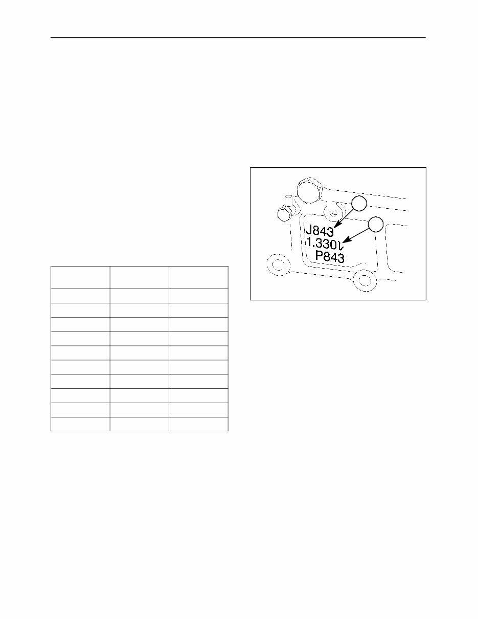
SECTION 1 - ENGINE SYSTEMS 1-2 GENERAL INFORMATION DESCRIPTION AND OPERATION This chapter describes the engine overhaul and repair procedures of the Models 1530, 1630, 1725, 1925, TC25, TC29, TC33, TC25D, TC29D, and TC33D tractors. Repair procedures are essentially the same for all models except as noted in the repair procedures. The tractors are equipped with three-cylinder in-line engines. They are all four cycle, overhead valve, liquid cooled engines. The engines are identified by a code, 1, cast into the lower right side of the cylinder block. NOTE: Numeric value, 2, under the Engine Code indicates displacement of the engine in liters. Engine Identification Tractor Model Engine Power Hp (Kw) J843 1530 25 (18.7) J843 1630 27.3 (20.5) J843 1725 29 (21.6) N843 1925 34 (25.5) J843 TC25 25 (18.7) J843 TC25D 25 (18.7) J843 TC29 29 (21.6) J843 TC29D 29 (21.6) N843 TC33 33 (24.6) N843 TC33D 33 (24.6) 1 2 Figure 1-1
This is a comprehensive service repair workshop manual for the New Holland model 1530 and 1630 Compact Tractor.
The manual contains all the necessary information to perform complex repairs on the entire 1530 and 1630 compact tractors, including engine overhauls.
Key Features:
661 pages, 13 sections
For do-it-yourself servicing, teardowns, repairs, overhauls, adjustments, and complete specifications
Clear and clean pages with detailed repair information and great pictures
Neatly organized in Adobe Acrobat with scalable, sharp images
Tons of illustrations, specifications, pictures, step-by-step instructions, and special tool info
Indexed and bookmarked for fast & easy navigation
Section Index:
Engine Systems
Fuel System
Electrical System
Clutches
Transmission Systems
Power Take Off Systems (PTO)
Differential, Rear Axle & Brakes
Hydraulic System
Steering Systems - Power Steering
Front Axle & Related Parts
Front Axle Optional Equipment
Wheels and Tires
Separating the Tractor
Upon purchase, you will receive a link via email to view, print, and save the manual for later use. It is indexed and bookmarked for fast and easy navigation, and is viewable in popular Adobe format.
About New Holland:
New Holland is a world leader in the design and manufacture of a full line of agricultural tractors and construction equipment. It is supported by a vast network of dealers and has a rich heritage in the industry.
History:
Started with one corn mill in Pennsylvania in 1895
Expanded into farm implements and found success with automatic hay balers
Acquired by Ford Tractor Operations in 1985
Majority interest sold to FIAT in 1990
Case IH and FIAT New Holland merged in 1999 to form CNH Global
New Holland produces both agricultural farm equipment and heavy construction equipment, including the 1530 and 1630 Compact Tractor models covered in this Service Repair Workshop Manual.
Recently Viewed
5,521,897Happy Clients
2,594,462eManuals
1,120,453Trusted Sellers
15Years in Business
Price:
Actual Price:
New Holland 1530 1630 Tractor Service Repair Shop Manual Workshop