Massey Ferguson MF 8220 Xtra Factory Service & Work Shop Manual
What's Included?
Lifetime Access
Fast Download Speeds
Online & Offline Access
Access PDF Contents & Bookmarks
Full Search Facility
Print one or all pages of your manual
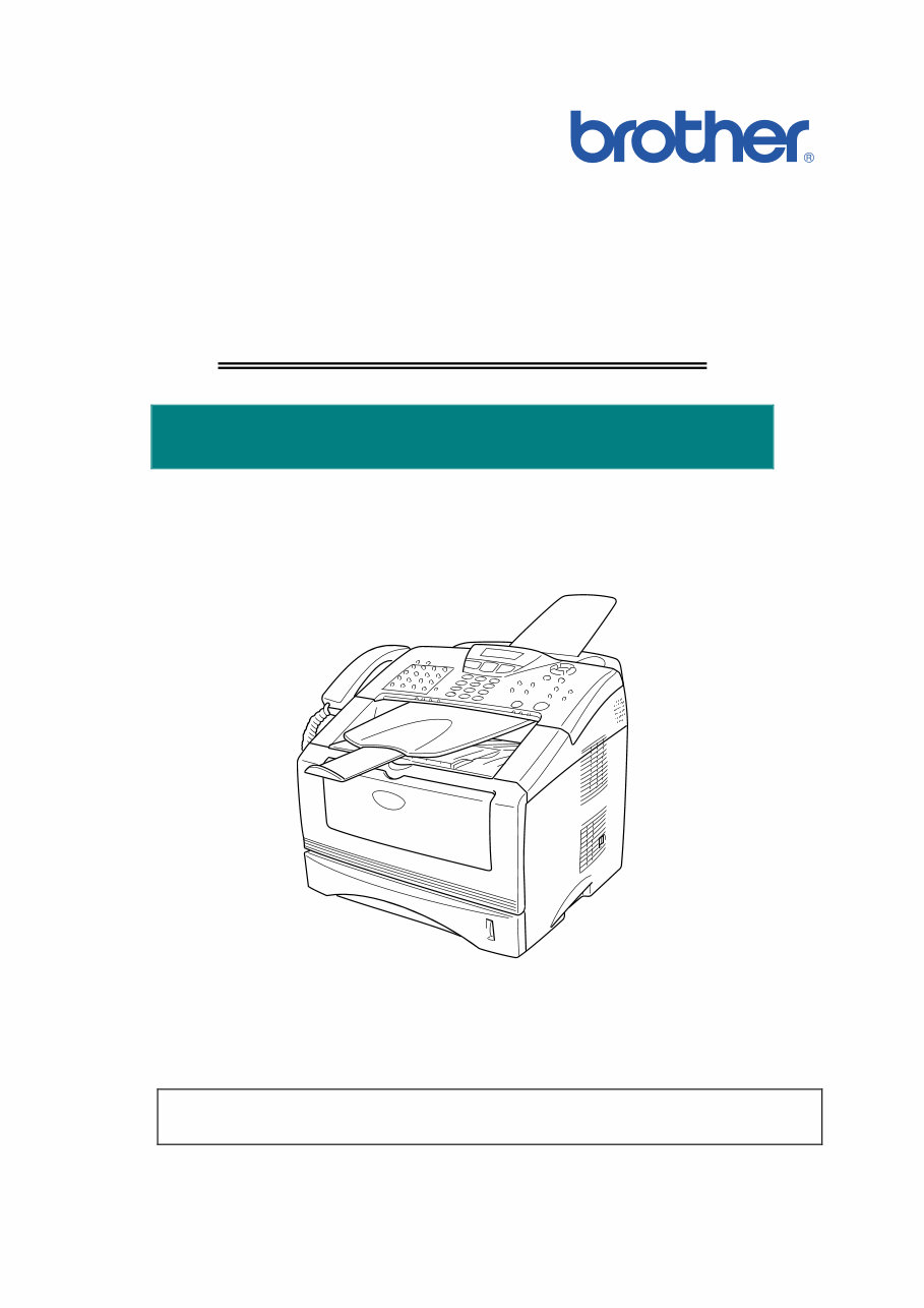
SERVICE MANUAL MODEL: MFC-8220 Read this manual thoroughly before maintenance work. Keep this manual in a convenient place for quick and easy reference at all times.
MFC-8220 SERVICE MANUAL i PREFACE This publication is a Service Manual covering the specifications, construction, theory of operation, and maintenance of the Brother machine. It includes information required for field troubleshooting and repair--disassembly, reassembly, and lubrication--so that service personnel will be able to understand machine function, to rapidly repair the machine and order any necessary spare parts. To perform appropriate maintenance so that the machine is always in best condition for the customer, the service personnel must adequately understand and apply this manual. This manual is made up of six chapters and appendices. CHAPTER 1: GENERAL CHAPTER 2: INSTALLATION AND BASIC OPERATION CHAPTER 3: THEORY OF OPERATION CHAPTER 4: DISASSEMBLY AND RE-ASSEMBLY CHAPTER 5: PERIODIC MAINTENANCE CHAPTER 6: TROUBLESHOOTING CHAPTER 7: MAINTENANCE MODE APPENDIX 1: EEPROM CUSTOMIZING CODES APPENDIX 2: INSTALLING THE UPDATE DATA APPENDIX 3: FIRMWARE SWITCHS (WSW) APPENDIX 4: CIRCUIT DIAGRAMS Information in this manual is subject to change due to improvement or redesign of the product. All relevant information in such cases will be supplied in service information bulletins (Technical Information). A thorough understanding of this printer, based on information in this service manual and service information bulletins, is required for maintaining its print quality performance and for improving the practical ability to find the cause of problems.
TABLE OF CONTENTS ii TABLE OF CONTENTS REGULATION ............................................................................................ viii SAFETY INFORMATION .............................................................................. x CHAPTER 1 GENERAL........................................................................... 1-1 1. OVERVIEW ............................................................................................................ 1-1 2. SPECIFICATIONS .................................................................................................. 1-2 2.1 General ............................................................................................................................. 1-2 2.2 Environment of Installation Site ........................................................................................ 1-2 2.3 Paper ................................................................................................................................ 1-2 2.4 Copy ................................................................................................................................. 1-3 2.5 Fax.................................................................................................................................... 1-3 2.6 Specifications for Document Feeding System.................................................................. 1-3 2.6.1 Specifications for document ................................................................................................ 1-3 2.6.2 Specifications for ADF......................................................................................................... 1-4 2.7 Printer ............................................................................................................................... 1-4 2.8 Interfaces .......................................................................................................................... 1-4 2.9 Consumable Items ........................................................................................................... 1-4 2.10 Network ............................................................................................................................ 1-5 2.11 Paper ................................................................................................................................ 1-5 2.11.1 Feedable paper ................................................................................................................... 1-5 2.11.2 Paper capacity .................................................................................................................... 1-7 2.11.3 Paper output ........................................................................................................................ 1-7 2.12 Printable Area ................................................................................................................... 1-7 2.13 Print Speeds with Various Settings .................................................................................. 1-8 2.14 Toner Cartridge Weight Information ................................................................................. 1-8 3. SERIAL NO. DESCRIPTIONS ................................................................................ 1-9 CHAPTER 2 INSTALLATION AND BASIC OPERATION ....................... 2-1 1. CONDITIONS REQUIRED FOR INSTALLATION ................................................... 2-1 1.1 Power Supply.................................................................................................................... 2-1 1.2 Environment ..................................................................................................................... 2-1 1.3 System Requirements for Brother Printer Solution .......................................................... 2-2 2. UNPACKING........................................................................................................... 2-3 3. INSTALL THE MACHINE ........................................................................................ 2-5 3.1 For All Users ..................................................................................................................... 2-5 3.1.1 Attaching the Supports ........................................................................................................ 2-6 3.1.2 Installing the Handset.......................................................................................................... 2-7 3.1.3 Installing the Drum Unit Assembly ...................................................................................... 2-7 3.1.4 Load Paper in the Paper Tray ............................................................................................. 2-9 3.1.5 Installing the Power Cord and Phone Line ........................................................................ 2-11 3.2 Installing the Driver & Software ...................................................................................... 2-13 3.2.1 For USB Interface Cable Users (For Windows ® 98/98SE/Me/2000 Professional/XP) ...... 2-13
MFC-8220 SERVICE MANUAL iii 3.2.2 For Parallel Interface Cable Users (For Windows ® 95/98/98SE/Me/2000 Professional/XP) ................................................... 2-18 3.2.3 For Windows NT ® Workstation Version 4.0 Users ............................................................ 2-23 3.2.4 For Optional NC-9100h Network Interface Users (For Windows ® 95/98/98SE/Me/NT/2000 Professional/XP) .............................................. 2-25 3.2.5 For USB Interface Cable Users (For Mac ® OS 8.6 to 9.2 Users) ...................................... 2-28 3.2.6 For USB Interface Cable Users (For Mac OS ® X 10.1/10.2.1 or greater Users) ............... 2-29 3.2.7 For Optional NC-9100h Network Interface Users (For Mac OS ® 8.6 to 9.2 Users) ........... 2-30 3.2.8 For Optional NC-9100h Network Interface Users (For Mac OS ® X 10.1/10.2.1 or greater Users) ................................................................. 2-31 CHAPTER 3 THEORY OF OPERATION ................................................. 3-1 1. ELECTRONICS ...................................................................................................... 3-1 1.1 General Block Diagram .................................................................................................... 3-1 1.2 Main PCB Block Diagram ................................................................................................. 3-2 1.3 Main PCB ......................................................................................................................... 3-3 1.3.1 CPU..................................................................................................................................... 3-3 1.3.2 USB ..................................................................................................................................... 3-4 1.3.3 IEEE 1284 ........................................................................................................................... 3-4 1.3.4 ROM .................................................................................................................................... 3-5 1.3.5 Flash ROM .......................................................................................................................... 3-6 1.3.6 SDRAM ............................................................................................................................... 3-6 1.3.7 Optional RAM ...................................................................................................................... 3-7 1.3.8 EEPROM............................................................................................................................. 3-7 1.3.9 Reset circuit ........................................................................................................................ 3-8 1.3.10 Engine I/O ........................................................................................................................... 3-8 1.3.11 Panel I/O ............................................................................................................................. 3-8 1.3.12 Video I/O ............................................................................................................................. 3-8 1.3.13 Scanner control ................................................................................................................... 3-9 1.3.14 Power supply ....................................................................................................................... 3-9 1.4 Engine PCB .................................................................................................................... 3-10 1.5 Power Supply.................................................................................................................. 3-11 1.5.1 Low-voltage power supply ................................................................................................. 3-11 1.5.2 High-voltage power supply ................................................................................................ 3-12 2. MECHANICS ........................................................................................................ 3-13 2.1 Overview of Printing Mechanism .................................................................................... 3-13 2.2 Scanner Mechanism....................................................................................................... 3-14 2.2.1 Document feeding and ejecting mechanism ..................................................................... 3-14 2.2.2 Scanner ............................................................................................................................. 3-14 2.3 Paper Transfer ............................................................................................................... 3-15 2.3.1 Paper supply ..................................................................................................................... 3-15 2.3.2 Paper registration .............................................................................................................. 3-15 2.3.3 Paper eject ........................................................................................................................ 3-16 2.4 Sensors .......................................................................................................................... 3-17 2.4.1 Document cover sensors .................................................................................................. 3-17 2.4.2 Toner sensors ................................................................................................................... 3-17 2.4.3 Cassette sensor / Paper empty sensor ............................................................................. 3-18 2.4.4 Paper eject sensor ............................................................................................................ 3-18 2.4.5 Document front sensor / Document rear sensor ............................................................... 3-19 2.4.6 Regist sensor .................................................................................................................... 3-19
TABLE OF CONTENTS iv 2.5 Drum Unit ....................................................................................................................... 3-20 2.5.1 Photosensitive drum.......................................................................................................... 3-20 2.5.2 Primary charger ................................................................................................................. 3-20 2.5.3 Transfer roller .................................................................................................................... 3-20 2.5.4 Cleaner .............................................................................................................................. 3-20 2.6 Toner Cartridge .............................................................................................................. 3-20 2.7 Print Process .................................................................................................................. 3-20 2.7.1 Charging............................................................................................................................ 3-20 2.7.2 Exposure stage ................................................................................................................. 3-21 2.7.3 Developing ........................................................................................................................ 3-22 2.7.4 Transfer ............................................................................................................................. 3-22 2.7.5 Fixing stage ....................................................................................................................... 3-23 CHAPTER 4 DISASSEMBLY AND RE-ASSEMBLY .............................. 4-1 1. SAFETY PRECAUTIONS ....................................................................................... 4-1 2. DISASSEMBLY FLOW ........................................................................................... 4-2 3. DISASSEMBLY PROCEDURE ............................................................................... 4-3 3.1 Power Cord....................................................................................................................... 4-3 3.2 Drum Unit ......................................................................................................................... 4-3 3.3 Paper Tray ........................................................................................................................ 4-4 3.4 Rear Cover C.................................................................................................................. 4-13 3.5 Access Cover / Battery ASSY......................................................................................... 4-14 3.6 Control Panel ASSY ....................................................................................................... 4-16 3.7 Document Scanner ......................................................................................................... 4-21 3.8 Outer Chute .................................................................................................................... 4-26 3.9 Rear Cover L/R............................................................................................................... 4-27 3.10 Side Cover L/R ............................................................................................................... 4-28 3.11 Top Cover ASSY ............................................................................................................ 4-29 3.12 Front Cover ASSY .......................................................................................................... 4-33 3.13 NCU ................................................................................................................................ 4-34 3.14 Fixing Unit ....................................................................................................................... 4-35 3.15 Laser Unit ....................................................................................................................... 4-44 3.16 Main PCB ASSY ............................................................................................................. 4-45 3.17 Base Plate / LV Insulation Sheet .................................................................................... 4-47 3.18 Engine PCB ASSY.......................................................................................................... 4-48 3.19 High-voltage PS PCB ASSY........................................................................................... 4-49 3.20 Low-voltage PS PCB ASSY............................................................................................ 4-49 3.21 Paper Feeder.................................................................................................................. 4-51 3.22 Frame L / Drive Unit ....................................................................................................... 4-58 3.23 Thermistor ASSY............................................................................................................ 4-62 3.24 Fan Motor 60 Unit LV / Fan Motor 60 Unit...................................................................... 4-62 3.25 Frame R.......................................................................................................................... 4-63 4. PACKING.............................................................................................................. 4-65 5. GUIDELINES FOR LEAD FREE SOLDER............................................................ 4-66 6. SCREW TORQUE LIST........................................................................................ 4-69 7. LUBRICATION...................................................................................................... 4-70 8. HARNESS ROUTING ........................................................................................... 4-71
MFC-8220 SERVICE MANUAL v CHAPTER 5 PERIODIC MAINTENANCE ............................................... 5-1 1. CONSUMABLE PARTS .......................................................................................... 5-1 1.1 Drum Unit ......................................................................................................................... 5-1 1.2 Toner Cartridge ................................................................................................................ 5-4 2. PERIODICAL REPLACEMENT PARTS .................................................................. 5-7 2.1 Fixing Unit ......................................................................................................................... 5-8 2.2 Paper Feeding Kit ........................................................................................................... 5-16 3. PERIODICAL CLEANING ..................................................................................... 5-20 3.1 Cleaning the Machine Exterior ....................................................................................... 5-20 3.2 Cleaning the Scanner ..................................................................................................... 5-20 3.3 Cleaning the Drum Unit .................................................................................................. 5-21 3.4 Cleaning the Scanner Window ....................................................................................... 5-21 3.5 Cleaning the Electrical Terminals ................................................................................... 5-22 4. MTBF / MTTR ....................................................................................................... 5-23 CHAPTER 6 TROUBLESHOOTING ....................................................... 6-1 1. INTRODUCTION .................................................................................................... 6-1 1.1 Initial Check ...................................................................................................................... 6-1 1.2 Warnings for Maintenance Work ...................................................................................... 6-2 1.3 Identify the Problem.......................................................................................................... 6-3 2. ERROR MESSAGE ................................................................................................ 6-4 2.1 Error Message on the LCD............................................................................................... 6-4 2.2 Error Codes Shown in the “MACHINE ERROR X X ” message........................................ 6-6 3. PAPER PROBLEMS ............................................................................................. 6-10 3.1 Paper Loading Problems ................................................................................................ 6-10 3.2 Original Jams.................................................................................................................. 6-11 3.2.1 Original is jammed in the ADF (Automatic document feeder) ........................................... 6-11 3.3 Paper Jams .................................................................................................................... 6-11 3.3.1 Clearing jammed paper ..................................................................................................... 6-11 3.3.2 Causes & countermeasures .............................................................................................. 6-15 3.4 Paper Feeding Problems ................................................................................................ 6-16 4. SOFTWARE SETTING PROBLEMS .................................................................... 6-18 5. MALFUNCTIONS.................................................................................................. 6-20 6. TROUBLESHOOTING OF THE CONTROL PANEL ............................................. 6-24 7. TROUBLESHOOTING OF FAX FUNCTIONS ...................................................... 6-26 8. IMAGE DEFECTS................................................................................................. 6-31 8.1 Image Defect Examples ................................................................................................. 6-31 8.2 Diameter of Rollers ......................................................................................................... 6-31 8.3 Troubleshooting Image Defect ....................................................................................... 6-32 8.4 Location of Grounding Contacts ..................................................................................... 6-50 8.4.1 Drum unit ........................................................................................................................... 6-50 8.4.2 Machine body & Paper tray .............................................................................................. 6-50 9. INCORRECT PRINTOUT ..................................................................................... 6-51
TABLE OF CONTENTS vi 10. NETWORK PROBLEM ......................................................................................... 6-53 10.1 Installation Problem ........................................................................................................ 6-53 10.2 Intermittent Problem ....................................................................................................... 6-54 10.3 TCP/IP Troubleshooting ................................................................................................. 6-55 10.4 UNIX Troubleshooting .................................................................................................... 6-55 10.5 Windows ® NT/LAN Server (TCP/IP) Troubleshooting.................................................... 6-56 10.6 Windows ® 95/98/Me Peer to Peer Print (LPR) Troubleshooting .................................... 6-56 10.7 Windows ® 95/98/Me Peer to Peer (HP JetAdmin Compatible Method) Troubleshooting ........ 6-56 10.8 Windows ® 95/98/Me/NT 4.0/2000 Peer to Peer Print (NetBIOS) Troubleshooting ........ 6-57 10.9 Brother Internet Print (TCP/IP) Troubleshooting ............................................................ 6-57 10.10 Windows ® 95/98/Me/2000/XP IPP Troubleshooting....................................................... 6-57 10.11 Novell Netware Troubleshooting .................................................................................... 6-58 10.12 AppleTalk Troubleshooting............................................................................................. 6-59 10.13 DLC/LLC Troubleshooting .............................................................................................. 6-59 10.14 Web Browser Troubleshooting (TCP/IP) ........................................................................ 6-59 10.15 Internet Fax Troubleshooting.......................................................................................... 6-60 CHAPTER 7 MAINTENANCE MODE ...................................................... 7-1 1. ENTRY INTO THE MAINTENANCE MODE ............................................................ 7-1 2. LIST OF MAINTENANCE MODE FUNCTIONS ...................................................... 7-2 3. DETAILED DESCRIPTION OF MAINTENANCE-MODE FUNCTIONS ................... 7-4 3.1 EEPROM Parameter Initialization (Maintenance mode 01/91) ........................................ 7-4 3.2 Printout of Scanning Compensation Data (Maintenance mode 05) ................................. 7-5 3.3 ADF Performance Test (Maintenance mode 08) ............................................................. 7-7 3.4 Test Pattern 1 (Maintenance mode 09) ............................................................................ 7-8 3.5 Firmware Switch Setting and Printout .............................................................................. 7-9 3.5.1 Firmware switch setting (Maintenance mode 10) ................................................................ 7-9 3.5.2 Printout of firmware switch data (Maintenance mode 11) ................................................. 7-11 3.6 Operation Check of LCD (Maintenance mode 12) ......................................................... 7-12 3.7 Operational Check of Control Panel PCB (Maintenance mode 13) ............................... 7-13 3.8 Receiver Volume Adjustment (Maintenance mode 16) .................................................. 7-14 3.9 Sensor Operational Check (Maintenance mode 32) ...................................................... 7-15 3.10 Received Data Transfer Function (Maintenance mode 53)............................................ 7-17 3.11 Fine Adjustment of Scan Start/End Positions (Maintenance mode 54).......................... 7-19 3.12 CIS Scanner Area Setting (Maintenance mode 55) ....................................................... 7-20 3.13 Paper Feed and Paper Eject Test (Maintenance mode 67) ............................................ 7-21 3.14 EEPROM Customizing (Maintenance mode 74) ............................................................ 7-22 3.15 Display of the Equipment’s Log Information (Maintenance mode 80) ............................ 7-23 3.16 Machine Error Code Indication (Maintenance mode 82) ................................................ 7-25 3.17 Output of Transmission Log to the Telephone Line (Maintenance mode 87) ................ 7-25 3.18 Cancellation of the Memory Security Mode (Not applicable to the Japanese version) . 7-26 APPENDIX 1 EEPROM CUSTOMIZING CODES ................................... A-1
MFC-8220 SERVICE MANUAL vii APPENDIX 2 INSTALLING THE UPDATE DATA .................................... A-2 1. INSTALLING THE UPDATE DATA TO THE MACHINE .......................................... A-2 1.1 Connecting the Machine to Your PC ................................................................................A-2 1.2 Setting up the Machine and Your PC ...............................................................................A-2 1.3 Installing the Update Data onto the Flash ROM of the Machine ......................................A-3 2. SETTING ID CODES TO MACHINES..................................................................... A-4 2.1 Connecting the Machine to Your PC ................................................................................A-4 2.2 Setting Up the Machine and Your PC...............................................................................A-4 2.3 Running the Setup Utility ..................................................................................................A-5 APPENDIX 3 FIRMWARE SWITCHS (WSW) ......................................... A-6 APPENDIX 4 CIRCUIT DIAGRAMS 4.1 Main PCB Circuit Diagram (1/6) .....................................................................................A-48 4.2 Main PCB Circuit Diagram (2/6) .....................................................................................A-49 4.3 Main PCB Circuit Diagram (3/6) .....................................................................................A-50 4.4 Main PCB Circuit Diagram (4/6) .....................................................................................A-51 4.5 Main PCB Circuit Diagram (5/6) .....................................................................................A-52 4.6 Main PCB Circuit Diagram (6/6) .....................................................................................A-53 4.7 Engine PCB Circuit Diagram (1/2) ..................................................................................A-54 4.8 Engine PCB Circuit Diagram (2/2) ..................................................................................A-55 4.9 NCU PCB Circuit Diagram (Europe) ..............................................................................A-56 4.10 NCU PCB Circuit Diagram (U.S.A.) ................................................................................A-57 4.11 Control Panel PCB Circuit Diagram................................................................................A-58 4.12 Low-voltage Power Supply PCB Circuit Diagram ...........................................................A-59 4.13 High-voltage Power Supply PCB Circuit Diagram (100V) ..............................................A-60 4.14 High-voltage Power Supply PCB Circuit Diagram (200V) ..............................................A-61 4.15 Back Light PCB Circuit Diagram ....................................................................................A-62
REGULATION viii REGULATION LASER SAFETY (110 - 120V MODEL ONLY) This printer is certified as a Class I laser product under the US Department of Health and Human Services (DHHS) Radiation Performance Standard according to the Radiation Control for Health and Safety Act of 1968. This means that the printer does not produce hazardous laser radiation. Since radiation emitted inside the printer is completely confined within the protective housing and external covers. the laser beam cannot escape form the machine during any phase of user operation. FDA REGULATIONS (110 - 120V MODEL ONLY) The US Food and Drug Administration (FDA) has implemented regulations for laser products manufactured on and after August 2, 1976. Compliance is mandatory for products marketed in the United States. One of the following labels on the back of the printer indicates compliance with the FDA regulations and must be attached to laser products marketed in the United States. The label for Japanese manufactured products MANUFACTURED: K BROTHER INDUSTRIES, LTD. 15-1, Naeshiro-cho, Mizuho-ku, Nagoya 467-8561, Japan. This product complies with FDA radiation performance standards, 21 CFR Subchapter J. The label for Chinese manufactured products MANUFACTURED: C BROTHER Corporation (Asia) Ltd. Shenzen Buji Nan Ling Factory Gold Garden Ind., Nan Ling Village, Buji, Rong Gang, Shenzen, CHINA This product complies with FDA radiation performance standards, 21 CFR Subchapter J. Caution Use of controls, adjustments or performance of procedures other than those specified in this manual may result in hazardous radiation exposure.
MFC-8220 SERVICE MANUAL ix IEC 825 (220-240V MODEL ONLY) This printer is a Class I laser product as defined in IEC 825 specifications. The label shown below is attached in countries where required. CLASS 1LASERP RODUCT APPAREIL Å LASER DE CLASSE 1 LASER KLASSE 1 PRODUKT This printer has a laser diode which emits invisible laser radiation in the Laser Unit. The Laser Unit should not be opened without disconnecting the two connectors connected with the AC power supply and laser unit. Since the variable resistor in the laser unit is adjusted in accordance with the standards, never touch it. Caution Use of controls, adjustments or performance of procedures other than those specified in this manual may result in hazardous radiation exposure. For Finland and Sweden LUOKAN 1 LASERLAITE KLASS 1 LASER APPARAT Varoitus! Laitteen käyttäminen muulla kuin tässä käyttöohjeessa mainitulla tavalla saattaa altistaa käyttäjän turvallisuusluokan 1 ylittävälle näkymättömälle lasersäteilylle. Varning – Om apparaten används på annat sätt än i denna Bruksanvisning specificerats, kan användaren utsättas för osynlig laserstrålning, som överskrider gränsen för laserklass 1.
Upon purchasing this manual, you will receive a .PDF file containing an email contact. After contacting us, you will receive a reply with a link to access the manual for your Massey Ferguson MF 8220 Xtra.
This comprehensive manual covers every aspect of your machine, providing detailed guidance for tasks ranging from an oil change to a transmission swap. With hundreds of pages, it includes numerous illustrations and easy-to-understand instructions to assist you. The manual also features a search function, allowing you to navigate through the content and print necessary pages.
Designed as a Factory Service Repair Manual, it offers a step-by-step approach to maintaining and repairing your machine, equipping you with the knowledge that factory-trained technicians possess. By utilizing the information in this manual, both professional mechanics and DIY enthusiasts can confidently make informed decisions regarding the maintenance and repair of their machine.
Our commitment extends beyond providing a high-quality service manual; we also ensure excellent customer service, guaranteeing your satisfaction.
Recently Viewed
5,521,897Happy Clients
2,594,462eManuals
1,120,453Trusted Sellers
15Years in Business
Price:
Actual Price:
Massey Ferguson MF 8220 Xtra Factory Service & Work Shop Manual