


SHOP MANUAL
MASSEY· FERGUSON
MODEL MF 65
SHOP MANUAL
MASSEY· FERGUSON
MODEL MF65
Tractor serial number stamped on instrument panel name plate.
Engine serial number stamped on side of engine.
I N D E X (By Starting Paragraph)
BELT PULLEY .. ......... .. .. .. ..... . .................. . . 158
BRAKES
Adjustment ...... .. .. ..... . ..... . ...... . ... . ..... ... ... 156
R&R and Overhaul. . ................. . .... .. ........ . ... 157
CARBURETOR (Except LP.Gal) ..... .. ... .. .. ..... ... .. .. .. 74
CARBURETOR (LP·GaI) ..... ............ .... .......... .. .. 75
CLUTCH (Enqlne)
Adjustment . .. .. ... ... ........ . ... .... ......... . ....... 113
Overhaul . .... ... .................... .. ........... . .... 117
Remove and reinstall ................ . ... ... ............. 115
NON·DIESEL COOLING SYSTEM
Pump and fan .. ....... ............................ ..... 107
Radiator ... ..... .... .. ..... ........ . ............ .. .. .. 103
Thermostat ...... ... ...... ..... . .... . ... .. ... .. . ....... 105
DIESEL COOLING SYSTEM
Pump and fan .. .. ... ..... .. . ... .. .. .... . ... .. ... ....... 108
Radiator .. . ... .. ... .. ............ .. .......... .. .. .. ... 104
Thermostat .... .. ... .. .................. ' ... ............ 106
DIESEL FUEL SYSTEM
Bleeding system ........ . .. ...... ......... ... . ....... .. 89
Cold weather starting ald . ............... ... ............ 99
Fuel Filters . .... ... ... .. ............ . ...... .. .. ........ 88
Injector nozzles
Overhaul ... ... .... . ....... . ............... . ....... .. 93
Remove and reinstall .... ...... .. ... .. ..... ... . ...... . 92
Testing . ... ..... ............. ... ... .. ...... ... ....... 90
Injection pump
Governor ... .. .. ............ ... . ... ..... ... .. ... . .. .. 97
R~~ove and reinstall. .... .. ... ... ... ... ... . ......... . 96
Tmung ...... .... .. .... .... ... .. .... .. ............... 94
PrEH:ombustion chambers . ....... ... ... . ................ 98
Trouble shooting .. ...... .. . ....... .. ... . ............... 87
DIFFERENTIAL
Remove and reinstall ... ........... . ..... .. .. ... . ... . .. . 145
Overhaul .. ... . .... •• ....... ... . .............. . ...... . 146
DIFFERENTIAL LOCK
Adjustment .. ..... ....... .. ....... .. ................... 148
Operation .... .. ...... ....... .... . ... .. .. ... ..... .. .. .. 147
Remove and reinstall . .... .. ....... . .................... 149
ELECTRICAL
Distributor .. . .. . .............................. . ...... . . 109
Generator ...... ..... . ... . ............. .. .......... .... 112
Generator regulator ..... . .... . ........... . ............. 112
Starting motor ............ ... ................ .. ... .. ... 112
NON·DIESEL ENGINE
Assembly R&R ... ... .......................... . ...... . 22
Cam followers . . ... ... . ..... .. ...... .. .. .. ............. 28
Camshaft .. .. ..... .. . . . . . . . . . . . . . . . . . . . . . . . . . . . . . . . . . . 33
Connecting rods and bearings ........................... 37
Crankshaft and bearings ..... .. .. .......... . ............ 38
Cylinder head .. .. .. .. .. . .. . ..... .. ... . .. .. . .. . .... .... 23
Cylinder sleeves . ............... ... .................... 35
Flywheel . ... .. .. .......... .. .. .. . ..... . ....... . ... .... 40
Front oll seal . ........ .. .......... ...... . .............. 31
Ignition timing .......... . ....... ..... .. ......... ... .... III
Main bearings ..... . ................ . .. . ........... . .. . 38
2
au pump ... .. .. .. .. ................ .... ............. . 41
Pistons .. .. ........... ....................... . .... ..... 35
Piston pins ...... .... .................................. 36
Piston and rod removal. . . . . . . . . . . . . . . . . . . . . . . . . . . . . . . . . . 34
Piston rings ... ....... ...... . . . . . . . . . . . . . . . . . . . . . . . . . . .. 35
Relief valve .. .. ...... .... ... .......... . ........ .. ... .. 42
Rear oll seaL. ... .. .. .. . .............................. , 39
Rocker arms .......... ...... . ......................... 29
Tappets .. .. .. .. . .. ....... ... ............ .. ... .. ... ..... 28
Timing gear cover .......... . ... .. .... . ........... .. .. .. 31
Timing gears ....... .. . ...... .... .. . .. ... .. .... . ....... 32
Valve guides . .. ... . .. . ... .. ......... . .............. .. . 25
Valves and seats ... . .... . ... .. .. .. . .... . ... .. ... .. .. . .. 24
Valve rotators ..... ........ ...... . .... ..... .. .... .. .... 27
Valve springs . .... .. . ................ ...... . ....... ... 26
Valve timing .. .•... ................ . ....... . .. .. ..... . 30
DIESEL ENGINE
Assembly R&R .. .. ... .. . .... .................... .. .. .. 43
Cam followers ..... . ...... ..... .. .. ... .. . ........ .. . ... 48
Camshaft .. ..... . .. . ... . . . . . . . . . . . . . . . . . . . . . . . . . . . . . .. 61
Connecting rods and becainga ... ... .. ... .. .... . ...... .•. 65
Crankshaft and becaings ........ ........................ 66
Cylinder head ..... . .. . ...... .. ....................... . 44
Cylinder sleeves ... .... ... .. ...... . ...... . ............ . 63
Engine adaptor plate .... .. . .. . . . .. . . . . . .. . .. . . . .. . .. .. .. 67
Flywheel ........... ................... .. ... ........... 69
Front oll seal. . . . . . . . . . . . . . . . . . . . . . . . . . . . . . . . . . . . . . . . . . . 52
Main bearings • . •• ... ............ ... ...... .. .. . ..... .. . 66
Oil pan ...... .. . .. .... .. .. . .............. .. ... . ....... 70
Oll pump .. .... ....... ..... .. . .. .. ... ... .. ............ 72
Pistons ....... .• .•. ....... .. ... .. ... ... .. .. ...... . ... .. 63
Piston pins .. .... .. ...... ..... ... .. ... .. . ... . .. . .... ... 64
Piston and rod removaL . . ............................ " 62
Piston rings . . . .... ................. ... .... ... . ....... . 63
Relief valve .... .. . ..................... .. .. . .......... 73
Rear oil seaL .. ...... . ..... . ....... . . . . . . . . . . . . . . . . . . . . 68
Rocker arms .. .. ..... .. ......... .... . .. .. .. ... ......... 49
Tappets . .. . ........ ....... . .... . .... ... .. ...... . .. . ... 48
Timing gear cover. ... .. .... .. ............ ... .......... . 52
Timing gears ... ... .. .................. . ...... . ........ 53
Timing gear housing. .. ... . . . . . . . . . . . . . . . . . . . . . . . . . . . . . . 60
Valve guides . .. . .. ... ............. . ..... ... .... . ...... 46
Valves and seats ...... ....... . ....... . ... .. , ....... . ... 45
Valve springs . ...• .. ... ..... .. ....... .. .. .. .. .. . ....... 47
Valve timing ............ . .. ... .... . .. . ........... . .... 50
FINAL DRIVE
Axle shaft and housing ... ....... . ... . ....... .. .. .. ... .. 152
Bevel gears . .... .. .. .. . ................ .. ... .......... 150
Differential R&R .. . •... ..... .... .. ....... .... .... .. .... 145
DiHerential overhaul .... ... .......... .. ... .. .. .. .... ... 146
Planetary gear assembly .... ..... . ......... ... ......... . 154
FRONT AXLE
Axle main member ........ ............................. I
Axle pivot pin and bushing . . . . . . . . . . . . . . . . . . . . . . . . . . . .. I
Dual wheels and spindle. . .. .. . . . .. . .. . . . . . . . . . . . . . . . . .. 5
Steering spindles ....... .. .. . .. .. ... ....... ....... ... .. I
Single wheel and fork .. ...... . . . . . . . . . .. . . . . . . . . . . . . . .. 4
Tie rods and! or drag links.. ................. .... ....... 3
Toe-In .. ... .. .. .. .. . .. ..... ............ .. ........... .. . 3
GOVERNOR. NON·DIESEL
Adjustment. major .. ..... . .............. .. .. ... ...... .. 101
Adjustment. minor .... ... ... .. ........ .. ............... 100
R&R and overhaul ..• ........... .. .......... .. .. .. .. . ... 102

INDEX (Cont.)
HYDRAULIC LlFT SYSTEM STEERING SYSTEM, POWER
Cylinder ... .. . .. ..... . . . . . . . . . . . . . . . . . . . . . . . . . . .. 19
Gear unit ..... . ..... . . . . . . . . . . . . . . . . . . . . . . . . . . . . 21
Filling and bleeding. .. . . . .. . .... .. . ...... .... 13
Adjustment ........ •.. ..... . ...... • .................. .. 163
Auxiliary control valve .. . ... .. ... .. ..................... 171
Lift cover R&R .. .. ...... . ...... .... . ........ . ... . ...... 168
Operating pressure .. ' . .. .. ............................ 15
Pedestal ............. . . . . . . . . . . . . . . . . . . . . . . . . . . . . . .. 20
Pump . .. .......... .. .. ... .. .... .. . ...... .. ........ .... 16
Relief valve ....... .. ...... .. ....... .. .. ... .. .... . ... . . 15
Operating pressure ...... .. ..... . .. .. .... . .. . .......... 165
Pump ........ . ........ ....... .. .. ...... . ............. . 166
Remote cylinder .. . .......... . . . .. ......... . .... .. .... 173
Rockshaft .. . .... .. . . . .. ... ... ................. 170
Work cylinder ............... . . . . ....... .. ....... .. ... 169 Trouble shooting .. . . . . . . . . . . . . . . . . . . . . . . . . . . . . . . . . .. 14
Valves .......................... .. ... ... .......... .... 17
IGNITION SYSTEM .. ...... ... . ........... .. .... ... .. .... 109
TRANSMISSION (Except Multi·Power)
Countershaft ... ... .... . .............. ... ... .. .......... 129
Drive shaft and gear .. ... .. ...... . ........... • ......... . 126
Main shaft ........... . . . .. .. .................... 128
Planetary unit ........ . ...... . ........... . ...... . .. ... 131
Reverse idler ........ . ................... .. .. ... .. .... 130
Shifter rails and forks ... .. .. ..... . ..................... 127
Remove and reinstall . . ... .. .... ...... . ...... . .... 123
R&R top cover ... .. .. .. . . ........ .. .. .. ..... . 124
Lp.GAS SYSTEM
Carburetor .. ....... . ......... • ........ .. ...... • ....... 75
Filter ....... .. . .. .. ... . ....... . ........ ..... .. ....... 80
Regulator
Adjustment .. ... . .. . . . . . . . . . . . . . . . . . . . . . . . . . . . . . . . . 86
R&R and overhaul ....... ..... ...... ... ..... . ........ 84
Relief valve .. ...... . . . . . . . . . . . . . . . . . . . . . . . . . . 79
Vaporizer
Test and adjust. .. .... . ... .. .......... . ..... . ....... . , 83 TRANSMISSION (Multi·Power)
R&R and overhaul .. . .. ................ .......... .. 81 Clutch ................... . ... .. ... ... .. .. .... 140
Control valve ... ... ... .. . ... .. .. ..... . ........ ... .... 133
POWER TAKE-OFF .. . ..... .. ...... . ....... .. . ...... .. .... 159
Countershaft .. .. ... .. ... .. ......... .. .................. 141
Input shaft ..... . ...... . .............. .. ........ 139
STEERING SYSTEM. MANUAL
Mainshaft ......... . ...... .... ... .. ...... .. .. . ........ . 138
Planetary unit .... . . .............. . ....... . ........ 137
Pump ............... . .......... ....... .. .... ..... 143
Adjustment ...... . ............... .. ..... . .. ... .. .... ... 6
Overhaul .. .... ... •... .. ............................... 11
Remove and reinstall. . . . . . . . . . . . . . . . . . . . . . . . . . . . . . . . . . . . 9
Remove and reinstall . . . . . . . • ......... ... ..... 135
Upper pedestal .. .. ...... ... .... .......... . .. .... . ..... 12
Shifter rails and forks . . ......... .. ......... ..... . 136
CONDENSED SERVICE DATA
GENERAL NON·DIESEL DIESEL
Torque recommendations ...... . .. ...... ... See End of Shop Manual
Engine Make. . . . . . . . . . . . . . . . . . . Cont'l Perkins Perkins
Engine Model. ........ .... .. ... G176 4A-203 AD4-203
No. Cylinders. . . . . . . . . . . . . . . . . . . 4 4 4
Bore-Inches . . . . . . . . . . . . . . . . . . 3.58 3.6 3.6
Stroke-Inches . . . . . . . . . . . . . . . . . 4. 38 5.0 5.0
Displacement-Cubic inches. . . . . . 176 203.5 203.5
Compression Ratio, Gasoline. . . . . . 7.1 :1
Compression Ratio, LP-Gas ...... . 8.1:1
Compression Ratio, Diesel .. ..... . 17.4: 1 18.5:1
Pi stons Removed From? . ' .. ..... . Above Above Above
Main Bearings, Number of? ...... . 3 5 5
Cylinder Slee\'eS ................ . Wet Dry Dry
Forward Speeds, No. of? ..... . .. . 6" 6 12
Reverse Speeds, No. of? ....... .. . 2* 2 4
Generator & Starter Make ....... . D-R D-R D -R
"12 forward, 4 reverse; if equipped with "Multi-Power" transmission.
TUNE-UP
Firing order. . . . . . . . . . . . . . . . . . .. 1-3-4-2
Intake Valve Tappet Gap (Hot) . . . . 0.016
Exhaust Valve Tappet Gap (Hot). . . O.ot8
Inlet Valve Face Angle . . . . . . . . . . . 30°
Inlet Valve Seat Angle . . . . . . . . . . . . 30°
Exhaust Valve Face Angle . . . . . . . . 44°
Exhaust Valve Seat Angle . . . . . . . . . 45°
Ignition Distributor Model. . . . . . .. 1112583
Breaker Contact Gap . . . . . . . . . . . . 0.022
Plug Electrode Gap . ............. 0.025-0.027
Carburetor, Gasoline . . . . . . . . . .. M-S, TSX695
Carburetor, LP-Gas. . . . . . . . . . . . .. Zenith
Aoat Setting, M-S . . . . . . . . . . . . . .. 1/ 4 inch
Injection Pump Make .... . ...... .
Injection Pump Model ... ....... .
1-3-4-2
0.010
0.010
44°
45°
44°
45°
C.A.V.
DPA
1-3-4-2
0.010
0.010
44°
45°
44°
45°
C.A.V.
DPA
TUNE·UP (Cont.) NON-DIESEL DIESEL
Injection Pump Timing. . . . . . . . . . . 18°BTC 24°BTC
Injector Nozzle Make. . . . . . . . . . . . C.A.Y. C.A.Y.
Engine Low Idle Rpm. . . . . . . . . . . . 450 500 600
Engine Load Rpm. . . . . . . . . . . . . . . 2000 2000 2000
Engine High Idle Rpm. . . . . . . . . . . 2150 2200 2175
Pta Load Rpm . . . . . . . . . . . . . . . . . . 720" 720 636
Pta No Load Rpm . . . . . . . . . . . . . . 774" 792 691
"Loaded rpm 636; no-load rpm 684, if equipped with ''Multi-Power'' transmission.
SIZES--CAPACITIES-CLEARANCES
(Clearances in thousandths)
Crankshaft Journal Diameter ...... 2.375 2.749 2.749
CflUlkpin Diameter ............ .. 2.062 2.249 2.249
Camshaft Journal Diameter:
Front . .. .. ................. 1.937 1.870 1.870
Center . . .. .. .. .... . ..... ... 1.750 1.860 1.860
Rear ......... ... .. .... ..... 1.687 1.840 1.840
Piston Pin Diameter .... . . . . . . . . . 1.125 1.250 1.250
Piston Ring Width:
Compression .... . .. ..... . ... 0.125 0.093 0.093
Oil ... ..................... 0.1 88 0.250 0.250
Main Bearing, Diameter Clearance .. 0.5-2.7 2.5-4.5 3.0-5.0
Rod Bearing, Diameter Clearance . . 0.7-2.7 2-3.5 2.5-4.0
Crankshaft End Play . ............ 4-8 2-10 2-14
Camshaft Bearing, Diameter
Clearance .............. ... .. 3-4.5 4-8 4-8
Camshaft End Play .............. 3-7 3-6 3-6
Cooling System-Quarts .. .. .... . 10.5 10 10
Crankcase Oil-Quarts ... . .... . .. 5 6 7
Transmission, Differential and
Hydraulic Lift-Gallons .. .. .. . 8 8 8
Power Steering Reservoir-
Quarts .. . .. .. ... ........ .. . 2/ 3 1-2/3 1-2/ 3
Steering Gear Housing-Pints . .. .. 2 2 2
3

Para9rophs 1-3
FRONT SYSTEM
2
--,
19
\~II
F19. MF1-StoJldo,d altd HI-arch fTc"t axle II~ all lIIodel MF6S. Recommended cn:1e li nd
play of 0. 002·0 ,Q08 Is adilisted wi th plllls 1151 . Toe- ill adlu, '_nt I, accompllJh. d by
tllfllin9 t l. rod hlbe 12 1.
8. Ou.t Hal 14 . Front pivot bUlllln. I. RlIIII Ita rod
~. TI. rod tube 9. Spindle b ... III .... 15. SlIlma
3. Steerlnl c ... nk arm 10. Axl-. uten.lon 16. TII ... ,t pi .. "
4. Ti e rod end 11. A"laeentermembu 17. 8pln<ll. and knuckl.
5. Lett U. rod tlltHo 12. Rea. pivot bu.llln. 18. 'J'hru,t Ma rl ...
II. WOOdruff kO 6. Spindle at.,rlnl .. rm 13. Pivot bracke t
AXLE ASSEMBLY
I. To remove the axle main (ce nter)
member (II-Fig. MFI), support trac _
tor under engine, remove the grille
l ower panel, disconnect tie rods from
the spindle steering arms and remove
both axle extensions and wheel as-
semblies from the center member.
Unbolt and remove the axle pivot
thr ust plate (16) and save shims ( 15 )
for relnstaUation. Remove the cap
screws retaining pivot bracket (13) to
the front support casting and remove
the pivot bracket. Pull center member
(11) forward and out of rear pivot
bushing (12) which Is located in the
front support casting.
The non-adj ustable axle assemb ly
used on Utility models Is renewed In
the same manne r except spindles
must be wit hdr awn from the one-
piece axle member.
•
Inside diameter ot new pivot bush-
ings is 1.877-1.879 for rear bushing
(12) and 2.002-2.004 for fr ont bushing
(14). Pivot pin diameter for a new
center member is 1.874-1.876 for the
rear pin and 1.999-2.001 for the front
pin. Renew center member and /o r
bushings if running clearance is ex-
cessive. Replacement bushings are
pre-sized and will not require ream-
ing It carefully Installed with a suit-
able arbor. Make certain, h owever,
that lubrication holes In bushings are
in register with similar holes in pivot
bracket and front support.
NOTE: On some early models, the
rear pivot bushing Is not staked In
pl ace In front support. When renew-
Ing the rear bushing, refer to Fig.
MF2 and proceed as follows: Remove
the old bwhlng and grease fitUng.
Use a l ong 7/32-inch drW bit and,
working up thr oug h the grease flt-
MASSEY-FERGUSON
ting hole, drill a small depression In
top wall of bushing bore. Install the
new bushing with grease hole in
bushing and support aligned, then
stake bushing in place by jngertlng
a slim punch through grease fitting
hole and indenting bushing Into pre-
viously drilled depression.
When Installing the axle center
member, reverse the removal proce-
dure and vary the number of shims
(15) to obtain a center member end
play of 0.002-0.008 when checked be-
tween rear face of pivot bracket ( 13)
Dnd Iront face of center member (11 ).
Shims are available in thicknesses of
0.00 2, 0.005 and 0.010.
SPINDLE BUSHINGS
2. Each a xle extension contains two
renewable bushings ( 9) which require
final sizing alter installation. Recom-
mended clearance between spind les
and bushings is 0.0035-0.005. Nominal
sp indle diameter is 1 %-inches for ad-
justable axle models; and 11k-Inches
for Utility models.
TOE. IN, TIE-RODS AND/ OR
DRAG LINKS
3. Tie-rod ends are of the automo-
tive type and are not adjustable to
compensate for wear.
Recommended toe-In 01 0- if. inch Is
adjusted by varying the len gth of the
right hand tie-rod. This is accom-
plished by loosening the tube set
screw and clamp bolt and turning the
tube (2- Flg. MFl) either way as re-
quired. Be sure the tube set screw is
In the f orward position before tight-
ening.
Fig. MF2 - 1. .1. pi, ot pin rear bUlhl_ ,
Inlt o ll ot ion .

MODEL MF65
1. Unk
2. 8t .. rilll ......
3. 8t .. rllll · ....
... WhM' fork
S.0I1 ... 1
•. IM.rllIlJ r .. .,.
1. N...u. tbrun Marlna:
t. 8M., ... rao.
I. Lowu MMIII "",r~
10. on Ral
11. on ... ,
l~. UII"'''' ,,_I. bearlll ll
II. ShIm ...........
It . Tt" .... at plal<o
15. Locll ... ~'
II. C.p~",
17. Dull,..,
Fig. MF) - Ex p lodH view of til •• 1191e WNfl forll. SIIppMt
c_hll l oM _kited port. 11* .a tM .... M"5 . bel
ploy of w,,", fork I. COllftol11tf11 by sill", ..... ,. 0).
16
15
Pa""Jl'GPhs 4-5
I. J.lnll
2. 8t .. rinr arm
3.011 ... 1
t. S.arl ... oou
~. n.arl ... eup
S. Lower pM .. t al
'. n.anar eup
•. a..nnr .......
8.011 .. al
10. Alli.
' :. Lo ... r"",lnd~
13 . StHrt,. am>
14. WaatM..
~I;~-~ 1
15
. IACkl'" ...... IM.
\: 1 1. Cap ..,raw
FI,. Mf.4 - &plo4H " .. .., of tho 4.en ..,_1 tricyc:l. 10..,.'
spIN", pH" hll 01111 , elot" ,.m. Spilld .. bowl.,. "011111
be oIIiwstoci to '_0'" 011 tIId ploy ..,ltholFt billdl.,.
SINGlE WHEIL & fORK
4. Th e fork mounted s ingle front
wheel II car ri ed In taper roll er bear-
in,. which shou ld be adjusted to pro-
vide a very ,Ught rotati ona l drag,
To remove the wheel f ork, support
tractor under engine and remove the
grill e lower panel. Open the irille
door and remove the .heet me tal dust
cap (1 7- FiJ . MF3). Remove the cap
screws (I6) r eLlinini the thrult plate
( 14 ) to upper end of wheel fork and
withdraw thrust plate (14) and shim
washen (13). Workin, throu,h open -
in, in the s upport casUn,. loose n th e
clamp bolt retaining s teerln, arm (3)
to wheel fork. Ralse front of tracto r
and at the same time, withdraw the
wheel fork fr om below. CAUTION:
Wheel fork must not be cocked dU r ing
removal or seals and need le bearln,s
may be damaled.
E xami ne needle bearln,s (9 and
12), s eals (:I , 10 and 11 ) and n eedle
thrust b ea rln, (6, 7 a nd 8) and r enew
any ques ti o nabl e parts. When InstaU-
In, the caged needle bearin,. (9 a nd
12 ), be . ur e to aU,n the a ll hol e In
tbe bearin,. with the 011 f eed hole l
In the support cas tin K.
In.tall the wheel fork by r eveni ng
the removal procedure and vary the
number of s him wa.hen (13) to pro-
vide the wheel fork wi th an up and
do wn e nd play of 0.002-0.008.
NOTE: Tho wh .. 1 'ork and at_rln<j1 arm
(3) ba .... a bllnd ,pUn. 10 IodUkllo ecm.a
m..-toJkrtioD.
DUAL WHIELS, LOWER SPINDLE &
LOWER PEDIST AL
5. Each of the dua l whee l. I,
mount ed on taper roller bearln,s
which sb ould be adj us~ 10 provide
a very sli gh t rot a tiona l dral.
To remove the l owe r spindle and
wheels ass e m b 1 y, s upport tractor
under en,ine and remove t he , rill e
lower panel. Open the g rill e door, un-
l ock and remove cap screw ( IS-Fig .
MF4), lock washer (15) and flat
washer (1 4). Working thr ough open-
Ing in the support casUng, loosen the
clamp bolt retaining steer ing a rm (13)
to the spindle. Raise front of tractor
and at the same time, withdraw the
spindle, axle and wheels assembly
from below.
Lower pedestal (6) can be remo ved
from the su pport casting at thls time.
Examine the bearing cones (4 and
8). cups (5 and 7) and seals (3 and 9)
and renew any questionable parts .
Install tne spindle and lower pedes-
tal by reversing the removal proce-
dure and U, h len ca p screw (18) to
remove all spindle end play without
ca usln, any bearing drag.
NOTE: Th. lowor 'piDdlo (12) and al .. rlDq
0.1111 U 31 hcrn a blind 'pllDo \0 'odlll<rt.
CClrr.CI irullaliatloD.
5
Paragraphs 6-9
MASSEY -FERG U SO N
MANUAL STEERING SYSTEM
For the pu~e. of Ih!. .ection, the model
MF6~ manual Ileerinq l y. t8m will Include
the cam and lev er type 98(!r unit, the houl-
ing of whic:b !. Inteqral with the troramlnlon
lOp cover: Clod the upper pedestal (llIIembly
which 1$ mount ed on the !roelar Iront sup-
port. Refer to fi g. MFS.
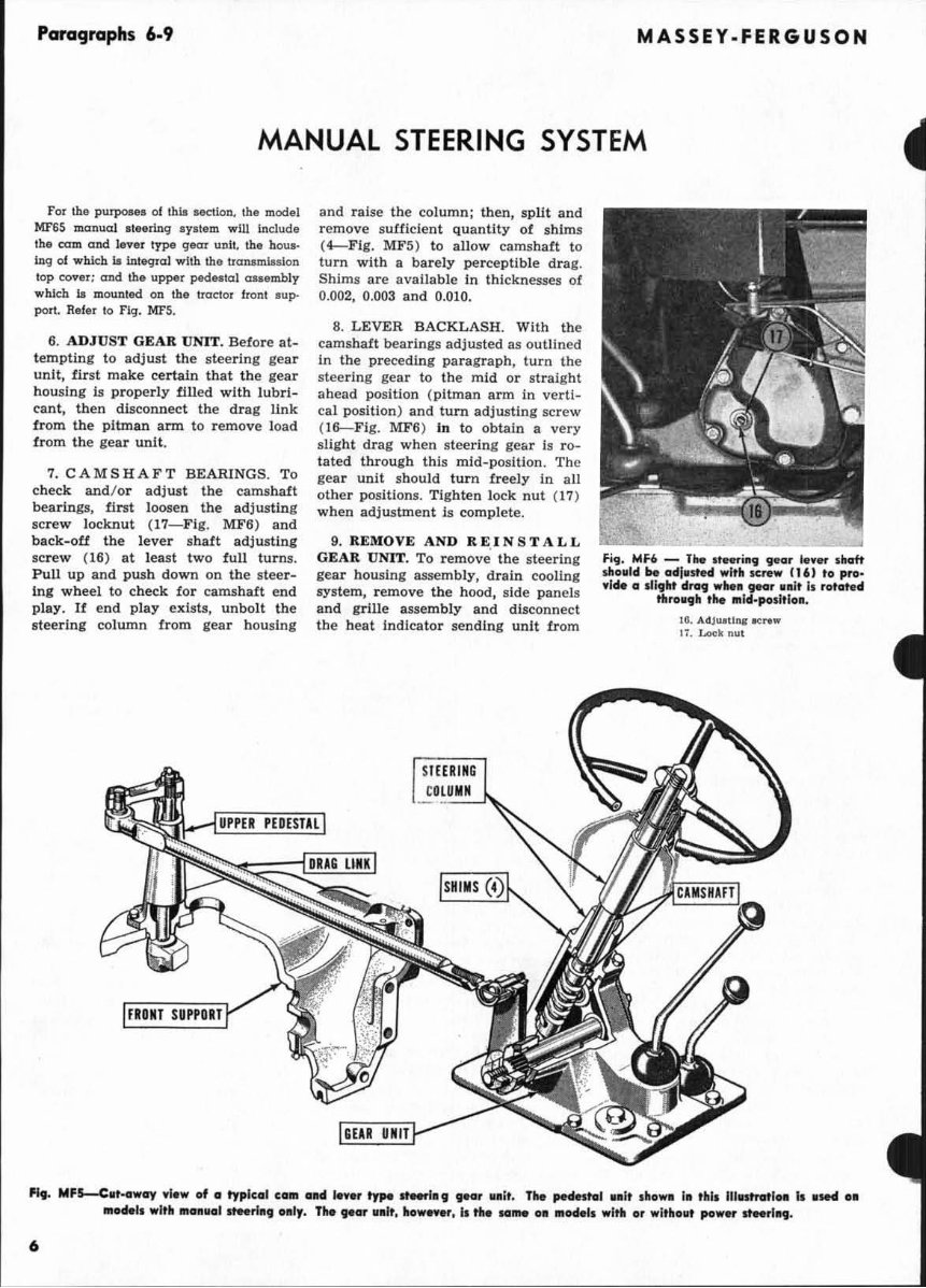
6. ADJUST GEAR UNIT. Befo re at-
t empting to adjust the stee ri ng gear
unit, first make certai n that th e gear
hOll slng is p rope rl y tilled with l ub r i-
cant, then disconnec t the drag I1nk
from the pit man arm to remove load
tr om the gear unit.
7. CAMS HA FT BE A RlNGS. To
check and/ or adj ust the camshaft
bea rings, first l oosen the adjusting
scr ew lockn ut (17-Flg. MF6 ) and
b ack-oU the l ever shaft adju sting
scr ew (16) at l east two full tu rns.
Pull up and push down on the steer-
i ng wh eel to ch eck for camshaft end
pl ay. If end pl ay exists , unbolt the
st e ering col umn fr om gea r h ousing
and raise the column; then, split and
remove su Cfi clen t quantity of sh ims
(4- F lg. MFS) to all ow camshaft to
turn with a ba rely perceptible drag.
Shims are available in thicknesses ot
0.002, 0.003 and 0.010.
a. LEVER BACKLASH. With the
camshaft beari ngs adjusted as outlined
in the preceding paragraph , turn the
steering gear to the mid or st r aight
ahead position ( pitman arm in verti-
ca l position) and turn adjusting screw
(I6--Fig. MFS ) In to obtai n a very
slig ht dr ag when steering gear is ro-
tated thro ugh this mi d-position. The
gear unit should turn fr eely in all
ot her positions. Ti g ht en lock nut (17)
when adj ustment is complete.
9. REMOVE AND R E.I N S TAL L
GE AR U NIT. To re m ove the steer ing
gear housing assemb ly, drain cooling
sys t em, r emove the hood, side panels
and grille assem bl y and disconnect
the heat indicato r se nding un it from
Ft g. Mf 6 - The ....... ing 'il ea l' Ie .. , shaft
dl a li id k oel ln," wi'. Krew IT6) ta pro'
" ,. a IU 911t 4"'9 wllell gear I . it Is rat ert.d
th,a l 9h the ," leI'po 5I t I0 1l.
16. AdJu.tll\&' .., .... w
Ii. L<>oknut
H,. MF~lIt_away .,I.w of a typlclIl CII," ON Ie". , type __ I" 9 fM' II lIl t. The ,.cs.. tGl ,.1, I ho •• I. this lII 'ttnrtlo. T , , M4 "
.. odel, wfth '"0111101 slMrlll g OI l, . The tear '"ft. how ........ I' ..... 10_ 0 11 " oeMl, wltll 0' wl,hollt po wer ItMrIlIg.
6

MODEL MF65
"
FI,. Mf7-bploded .lew of tile C_ G ....... ty,. .... ri ..... ' nit. C ... hGft Mor-
I.,. .114 .... , bod.losll .. odi _ 5tDba.,
S . ... 4)< •• 11 .... N III
I. Woo4ruttt 111.,.
'!. 8tM.I ... ~ll1m ..
t. Pitman ann
10. 01 1 ... 1
11. r-1II I\"t
I' . Slda .....
'I . 0 • • ""1
-.1Id "" • • ,
II. Bu.ahlnp
I '!. H OUAl .... 20. Bearl,.. .... mbl'
3. "0" ri ft , 13. UOIl.! .... pl u, 21. BM.r1"" ~r1""
4. ShIm.
~. ~t.ln •• rl na
t. n .1l CliP
14. lAver.t"d
( trl q cl& modal e)
14A . .... v •• ~\ld
""
~. Be .. l .... IJII rl ftS
~. 8H1
T. a .... lna' ban. 1 .. " le JTIOd,. I, l 14 . St"rlna eoh.mn
-.
I. C. m.ahaft
._mbl7
I~ . .... v ... hatt
U, r.ll_t
I' . AdJ... U.... .., .....
the water outlet elbow. Disconnect
cable from starting motor and wlrell
from coil, headlights and generator.
Disconnect traciormete r cable from
generator, choke rod from carburetor
and oil ISle line from fliht side of
cylinder bl ock. Shut oU the fu el and
remove the fuel line . Unbolt the fuel
tank from its rear support, loosen the
fuel tank front s upport bolts and
bl ock-up bet wee n fu el tank and
rocker cover .
Note : Some mechanics pre fer to
completely remove the fuel tank . Dis-
connect throttle rod and rear balJ
joint. Disconne ct battery cabl es and
remove battery. Disconn ect tall light
wires and wires from slarter safety
switch . Unbolt battery platform fr om
engine and remove steering wheel,
steerin, wheel WoodruU key, felt
washer (25-FI,. MF7 ), spring ( 22),
ch rome cap (24) and r ubbe r seal (23 ).
Remove the cap screws retaining th e
Instrument panel and battery platfonn
FJq . MH-Typlcol .pper
pedfttal _d dN, II_ I .-
d allatl_ o. all .0tIe1,
o "llpp od w "" _. oal
,t oo rl., o.d " Iostable
tyJM! fro.. _Ie. The 10 -
staUatlOtl .1 tr i cycl e
IIIadell k ,I.dlar oxce pt
fOf details af the lawe,
st..ri., al1ll.
ParaCJraphs 111.11
to the sleerin, gear h ouam, a nd lif t
the instrument panel and battery plat-
Corm assembly from tractor.
10. Disconnect dra& link from pit-
man srm. remove t be cap scr ew. re-
t ai ning the transmlssJon cover to
tla ns mluion boustna: and lif t tbe
It ee rin, ,e ar and transmission cover
unil Irom tractor.
11. OVE RHA UL GEAR UNIT. Tbe
steerin , , ear unit an be overhauled
with out removin, the ,ear housing u-
s embly from tractor by removing the
In st rume nt panel and battery platform
assembly as outlined In paragraph 9.
Remove pitman ann from l ever
s haft and remove the gear housing
side cover (l8- Fig . MF7). Withdraw
the lever shaft and stud assembly.
Examine the stud and re new same it
damaged or excessively worn .
Note : On axle type tractors, the
s tud (14A) II mounted in roller bear-
in gs, but component parts 01 tbe stud
assembly are not sold separately.
When wtallin, a new lever stud
(14A). tig hten nut (N) until a rollin,
to rque of 6-8 Inch-Lbs. is required to
turn the stud In its bearings .
Remove the steering column and
ge ar housing cover (2) and save &hlml
(4 ) for reinstallation . Withdraw the
cams han , remove s nap rinis (5 ), cups
(6) and bearini balls (7). Examine
all pa rts and renew any which are
Qu estionable .
New lever shaft bush in,s ( 11)
should be reamed after insla ll ation, 11
necessary , to provide an Imide di-
ameter of 1.6235-1.625. The lever shaft
(15) s hould have a clearance of O.OOO~-
0.003 in the bus hin gs.
7

Paragraphs 12-16
When r eassembling the unit, adjust
the camshaft bearings as in para g raph
7 and the l eve r b ac klash as In para -
graph 8.
12. R&R AND OVERHA UL UP PE R
PEDESTAL. To remove the upper
p e des t a I, first remove the g rille
screens and the l eft s ide pan el as
s hown in Fig . MFa. Loosen clamp bolt
(B) retaining stee ring arm to lower
end of pedestal s halt and disconnect
the drag link at forward end. Remove
the cap scr ews r etaining upper pedes-
tal to iront support casting and re-
move pedestal assembly from tractor.
Remove the nut ( 26-Fi g. MF9 ) re-
taining steer!n, arm ( 29 ) to pedesta l
.haft a nd r emove the s tee ring a rm .
Remove pedestal s hait (30), e1l:amine
all parts and re new any which are
damaged or show wear. Ream new
bushings ( 32 ), after installation , to an
Inside diameter of 1.5005- 1.5{l1,. Ped-
esta l shaft (30) shou ld have a clea r-
ance of 0.0005-0.002 In the bus hin gs.
FI,. ""H - Exploded 'fJe. of t ... ' pper
pe4est ol OM co_po-n IIM4 __ oMl
""F65 witll _ ... 1 .....u..
zt. NIIl
21. Look .a-h.T
28. Flat ... her
:tIl. Uppn a, .. nne
.~
10. Plodutal ,hall
I I. 0 .... ' ... 1,
n. Buthlnll't
SJ. PIod.~.1
.1.:1. ,. . .... , "'PP<>"
POWER STEERING SYSTEM
NOTE: The lIlo:lnlenonce 01 abaclule e1een-
llneu of all pam le 01 IItlllost Imponanee in
th. operation and te'v lelnq of th, bydl(IUlic
po",er It .. rlnq Iystelll. Of lIq1.Ial importance
Ia th, avoidance 01 nleu or bura on any of
tb, WOtldr.q pculll.
FILLING AND BLEEDING
13. Fl uid capacity fo r the compl ete
power steering system is ~ qt. for
non-diesel models and 1 ~ qt . for
diesel models.
Only automatic transmission fluid,
Type A Is r eco mmended for use In the
power s teer ing IYst em. R eservoi r fluid
l eve l and the paper filt er el ement in
reservoir should be checked every
750 hours of operaUon or more oft en
In severe dust con diti ons. Reservoir
fluid l evel Ihou.ld be main t ained 1/ 4-
~_ inch above the filter element.
To bl e ed the IYstem, fill relervolr,
start engine and tum th e steering
wheel t ull r ig ht and full le ft several
times to bl eed air fr om the sys tem ;
8
then, refill r ese rv oir to the proper
level.
TROUBLE SHOOTING
14. The accompanying table li sts
troubles which may be encountered
In the operatio n ot the power steering
system. The procedUre for correcting
most of the troubles Is evide nt ; lor
those not readily r emedied, refer to
the appropriate subsequen t para-
graphs.
SYSTEM OPERATING PRESSURE
AND RELIEF VALVE
15. A pressure t est ot the hydraulic
circuit wlll disclose w h e the r the
pump, relief valve or some othe r unit
in the system I, malfunctionin g. To
ma ke such a test, proceed as follows:
Connect a p ressur e test gage and
s hut- oU val ve in series with the pump
preuure line at shown in Fi g. MFI0.
Note that the preuure gage Is con-
nected in the circ uit b et w een th e
MASSEY-FERGUSON
""".
FkJ . ""FlO - Preu.,.. '0ge alld ,h llt-aH
veri". IJilltoilotloJil for chotcklll, t ile po we,
ItMrI JII, JpteM opeNtl., prOWl re. At 2000
e",III' rpm, the plllllP a.tput pfelillf'
IhOliid be 1100 psi.
sh ut- oU valve and the pump . Open
the s. hut-off va lv e and run engine at
l ow Idle speed until a ll is warmed .
Advance the en gine speed to 2,000
rpm , close the sh ut -off valve and re-
tAin In the closed position on ly long
enough to observe th e gage reading.
Pump may be se riously damaged if
valve Is left in the closed pos iti on lor
more than 10 seconds. If gage reading
Is 1,100 psi with the s hut-off valve
closed, the pump and re lie! valve are
O. K. and any trouble Is located In
the contr ol valve, power cylinder and /
or connectio ns.
If the pump output pressure Is more
than 1,100 psi, the rell el valve is either
improperly adjusted or s tuck in the
closed pos ition . U th e output pressure
is less than 1,100 psi, e ither the rellel
val ve Is improperl y adjusted or the
pump req u ires ove rhau l1ng. In any
even t, the first ste p In eliminating
trouble Is to adjust the relief valve .
This may be accomplished by remov-
in g the r eservoir cover and rilter e le-
men t on non - diesel models; or cap
plug on t op of pump ( dlesel.s), and
turning the r elle! valve adjusting
screw ( 20-Fig. lIU'U) eit her way as
required . One tu rn 01 the adj usti ng
screw wlll increase the out put pres-
s ur e approximately 300 ps I. Be s ur e to
stake the screw alte r adjustment Is
complete. U r elle! valve adj ustment
will not restore the pressu re with the
s hut- off valve cl osed, re new the pump .
PUMP
16. Component parts are not avail-
able l or the hydrauli c pump. U tr ouble
d evelops ther ei n, rene w th e pump a,
an asse mbly .

MODEL MF65
"
II Ii 11
.. J.,J 11 Ii J
Fit. MFll - h,lodod
" ...... of '" power ,,",.
I.. p •• p. TIl_ p •• p 11
drh' .. fr_ ,... ... 1 .0
tI-'-t .,..., trol. OM eM·
Ii ...... . ,.".dMOtefy fOil,
,.110111 per .1'lIte at a ll
• ",i_lpeecI.f 2000 rpM.
If ,_, it f • • Ity, re_
t .. c_~ _I , as C Olli -
po ... porta aN aot cot·
.I .... d.
t. nIt ... , ...... It
~. EI_nt _I CliP
3. at ...
•. Nil'
~. Cott .. pin
Ii. Dri ... _r
~. 8Mrt ... _ .
S. ""." .1",
It. Ilall toearl,,"
10, W9OOl ..... 1! ka,.
II . Ori .... llalt
12. W_ .... UkQ'
I!l. 8 .. ap TI".
I~. On ... l
I:,. N_I ..... rln ...
rI~ ~"
• () U 12
, 11 ,.
- r /~ I •
"'''' /J'r ~1) } i~' ' .. .
nn 11 ~ ~
-,
W.Drl ..... II .. •
I;. I ....... ., bod,
1~. Dow. ' pi n
til , "0" tt na
:!II. ""IJ".u", .c,...
~1. Sp.lnlll
~. I t-lief valY.
,"".h.1t no! ball
",. ''0'' .Ina
2~. "0" 1"1,..
:l.~. a-._.lft1:
STEERING VALVES
All Mod e ls Pr ior 650 369
t7. R&R AND OVERHA UL. To re-
m ove th e power sl ee rin g va lv es, open
the gr ille doo r and di sco nn ect the
hose lines fr om the va lve unit . Re-
ro. "oILo ...... u
'!:t. r"l\oW ... _.~'.rt
:!II. _ . J)t n
move pin (P- Flg . MF12), unbolt and
r em ov e the valve unit [rom cy lind er.
To disassemble the unit , di sconnect
the adjusting linka ge from link (1 0-
Fi g. MF13 ) and pry out the dust seal
re tainer ( 6) . Ez\ract the du st seal (7),
re move snap rin&" (8) and withdraw
PCll'CKJraphs 17.18A
the valve com ponents from the body .
Thoro u&"hly clean all parts and re new
any which are ques Uonable. When re-
assembling, be su re to renew aU "0 "
rlnl ' and seab and install a new seal
retaine r (6) .
18. After the un it is insta ll ed on
tractor, fill and bl~ t he system as
in paralraph 13 and adjust the linkage
as follows: With th e e ngi ne runn ing
at 1500 rp m and pin (P- Fi g. MF12)
removed, loosen jam nut (N) and
ti g hten the adjusting pin (8) until It
bottoms. Loos en the jam nu ts on the
adjus tin g link and t um s leeve (B)
e ith er way as requi r ed un~ iI pin ( P)
cnn be fr ee ly in stalled. Ins tall c otte r
pin s in pin (P ) and tighten the link-
age jam nuts. Ba ck-oU the adjust-
Ing pin (S) seven full turns and
t ig hten jam nut ( N).
Now, turn the s teering wheel to
both ex tr eme positions and make cer-
tilin the sys tem pressure reli ef va l ve
ope ns. If va l ve will not open when
wheel is turned to the right , lengthen
th e li nkage by turning sleeve (B). It
valve wlll not open when wheel Is
turned to the left, sho rten the linkage.
All Mod e l. After 650 368
lSA. As sho wn In Fig. MF13A, the
va lv e hous ing Is integral with the cyl-
Inder e nd cap (2). To ove rh aul the
un it. remove the gr ill e screens, r e-
move pin (P) and disconnec t the hy-
POWER STEERING SYSTEM TROUBLE·SHOOTING CHART
Blndlnq. worn or bent m~hankal Unkoqe .• ...............
Insu.f1ldent fluid In r_n-ou.
Lou 01
Power
AuJ.taDCe
*
*
Low pump preuwe . , .... " .................. •• , .... . .... *
SI1cli:inq or blnding ,,01 .. spool. ............. .. ••• ........
Damaged OT r.strlcted hON or tubing .... . ......... •..• . •.
Wronq nuld In s.,.tem .................... . ............. .
Improperly adjueted tie rod. or drag 1J.nb .... •••• ••.•••.••
Steering anll8 not pc»lUoned properly . .... .. ...... . ...... ••
Au In • .,. telrl .. ............................ ............ .
Plugged Wi er elelrlent ............ , ............... ... .. . . .
F aulty cylind.r ......... .......... ..... ..... ••• •• .• .....
Fa ulty Iinkag. adjllStlflent .............. .. .... ... ••• .... .•
Improper odjusllng pin elecuo:ne. ........ • ......... .... .. .
*
*
*
*
*
Power
Aublcuu:.
lDOne
Du~llon
001,
*
*
*
UneqUal
TumlDo
Ro:dlWl
*
*
*
*
*
*
*
*
*
*
*
*
*
*
*
*
*
Unequal
--
Ell,.
*
*
*
•
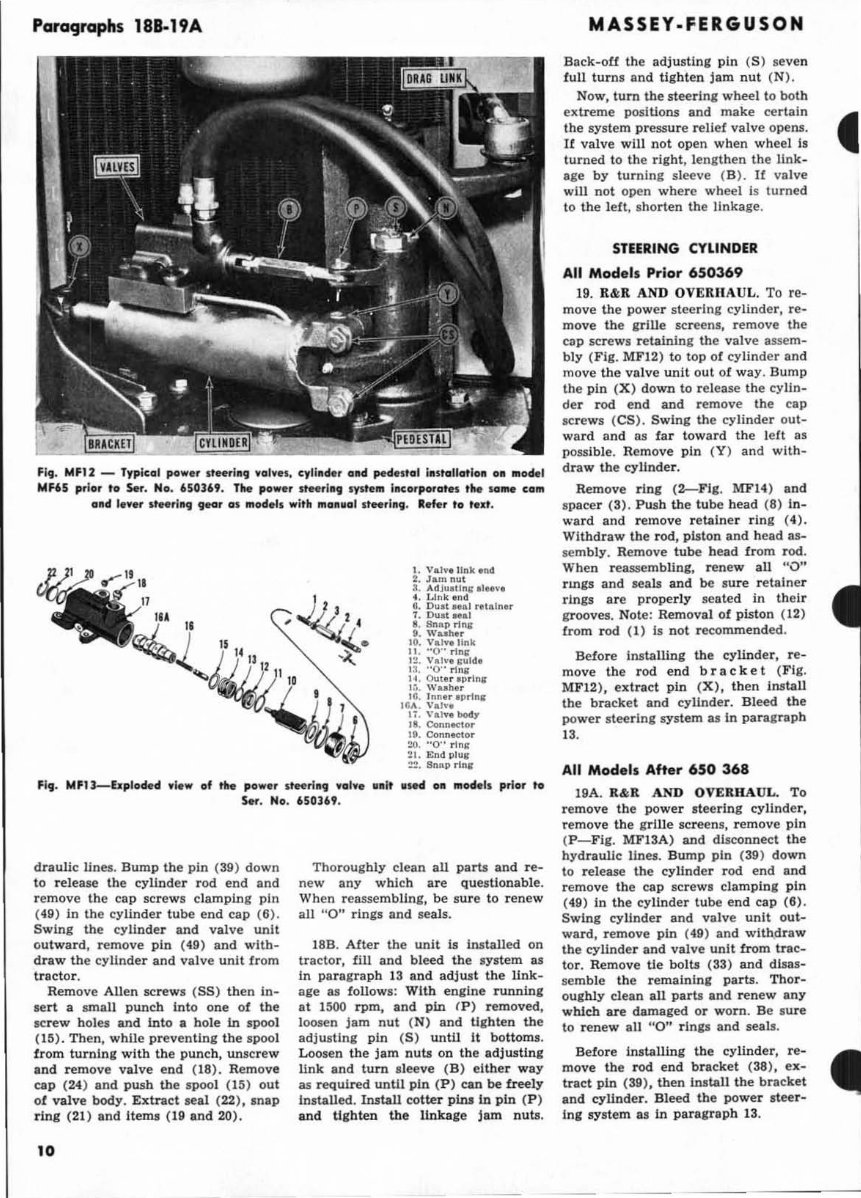
Paragraphs 181-19A
Fit. MF12 - Typical po w.r ,tH, I"III \, 01." . cytilld.r a ll d pedestal I. stollotloll 011 .odel
MFli5 pri or to Set. No. 650169, TIN powe, s'H, I1 9 ays tl ... incorporat" the 10_ calli
Gild I ••• , " .. rlllljI tear as "'odels with 1110111101 ,t .. rI1l9 . Ide, to lu t.
JJ)
~"
~.
-~
I. Vat... Unl<.nd
:. Jan, nul
1. "dju.lln~ "I .. ".
4. W nk tnd
6. D", at ... 1 ,.talna.
1. Dun ... ,
•• I!ftap rl l\i'
t. Wuhar
10. Valva link
II . "0" rln¥
I~. Va h'. ~I".
I~. "0" rllI&
I~. Out .. IIP.ln ..
I.~. Wube.
IG. Inne r Iprlna
16... . V"h '.
I ~. V .. ",.b04,.
'I. ConnKt or
II'. Connector
20. "0" rln ...
~l. End plnl
:~. Snllp .Inl
Fit . MFll-bplodtld view of the po w. , ,'H,III, 'ral "l .. lilt .sed all lIIod,l, prior to
S .... No . 650l69,
draulic lines. Bump the pin (39) down
to release the cylinder rod end and
r emove the cap screws clamping pin
(49) In the cylinder tube end cap (6) .
Swing the cylinder and valve unit
outward, remove pin (49) and with-
draw the cylinder and valve unit from
tractor.
Remove Allen screws (55) then in-
sert a small punch into one of the
screw holes and into a bole in spool
(15). Then, while preventing the spool
from turning with the punch, unscr ew
and remove valve end (18). Remove
cap (24) and push the spool (15) out
of valve body. Extract seal (22), snap
ring (21) and items (19 aDd 20).
10
Thoroughly clean all parts and re-
new any which are questionable.
When reassembUng, be sure to ren ew
all "0" rings and seals.
18B. After the unit Is InstaUed on
tractor, fill and bleed the system as
in paragraph 13 and adjust the link -
age BI follows: With engine runDini
at lMO rpm, and pin (P) removed ,
loosen jam nut (N) and tighten the
adjustlni pin (5 ) unto it bottoms.
Loosen the jam nuts on the adjusting
link and turn sl eeve (B) eltber way
as required unUl pin (P ) can be freely
Installed. Install cotter pinlin pin (P)
and tlgbten the linkage jam nuts.
MASSEY-FERGUSON
Back-oU the adjusting pin (5 ) seven
full turns and tighten jam nut ( N) .
Now, turn the steering wheel to both
extreme posiUoll5 and make certain •
the system pressure relief valve opens.
If valve will not open when wheel I!
turned to the right, l engthe n the link-
age by turning sleeve (B ). If va lve
will not open where wheel is turned
to the left , s horten the linkage.
STEERING CYLINDER
All Models Prior 650369
19. K&R AND OVERII AUL. To re-
move the power steering cylinder, re-
move the irlUe screens, rem ove the
cap screws retaining the valve asse m-
bly ( Fig. MFI2) to top of cylinder and
move the valve unit out of way . Bump
the pin (X) down to rel ease the cyUn-
der rod end and remove the cap
screws (C5). Swing the cylinder out-
ward and as f ar toward the left as
possible. Remove pin (Y) and with-
draw the cylinder.
Remove ring (2-Flg. MF14) aDd
spacer (3). Pusb the tube head (8) In-
ward and remove r etainer ring (4).
Withdraw the rod , plston and head as-
se mbly . Remove tube head from rod.
When reassembling, renew all "v"
rmgs and seals and be sure retainer
rings are properly seated in their
grooves. Note : Removal of plst on ( 12)
from r od (1) Is not recommended .
Before Installing the cylinder, r e-
move the rod e nd bra c k e t (Fig.
MF I 2), extract pin (X), then install
the bracket and cyllnder. Bleed the
power s teering s ystem as in parairaph
13.
All Models After 650 368
19A. R&R AND OVERHAUL. To
remove the power steerIng cylinder,
remove the , rille screens, remove pin
(P-Fig. MFI3A) and disconnect the
hydraulic lines. Bu mp pin (39) down
to release the cylinder rod end and
remove the cap scr ews clam ping pin
(49) in the cyli nder tube end cap (8).
Swing cyUnder and valve unit out-
ward , remove pin (4.9) and wllh$iraw
the cylinder and valve unit from trac-
tor. Remove tie bolts (33) and disas-
semble the r emalnlni parts. Thor-
oughly clean all parts and renew any
which are damaged or worn . Be sure
to renew all "0" rings and seab.
Before Installing the cylinder, re-
move the rod end bracket ( 38), ex-
tract pin (39), tben install the bracket
and cyUnder. Bleed the power Iteer-
ing system as in paragraph 13.
You're Reading a Preview
What's Included?
Fast Download Speeds
Online & Offline Access
Access PDF Contents & Bookmarks
Full Search Facility
Print one or all pages of your manual
€27.99
Massey Ferguson MF65 MF-65 Shop Repair Service Manual
Viewed 87 Times Today

What's Included?
Fast Download Speeds
Online & Offline Access
Access PDF Contents & Bookmarks
Full Search Facility
Print one or all pages of your manual
€27.99

Secure transaction
What's Included?
Fast Download Speeds
Online & Offline Access
Access PDF Contents & Bookmarks
Full Search Facility
Print one or all pages of your manual
Description
This is the shop repair service manual for the Massey Ferguson MF65 MF-65, a valuable resource for both professional mechanics and DIY enthusiasts. It is essential for ordering parts or making repairs, as it contains detailed blown-up illustrations and a comprehensive parts list for your tractor. Additionally, the owner's manual for the tractor is included.
The manual is available in English and is compatible with Win/Mac. It comes in Adobe format, featuring numerous pictures and diagrams for easy reference. All pages are printable, allowing you to conveniently take the necessary information with you into the home, office, or repair shop without worrying about getting grease on the manual.


