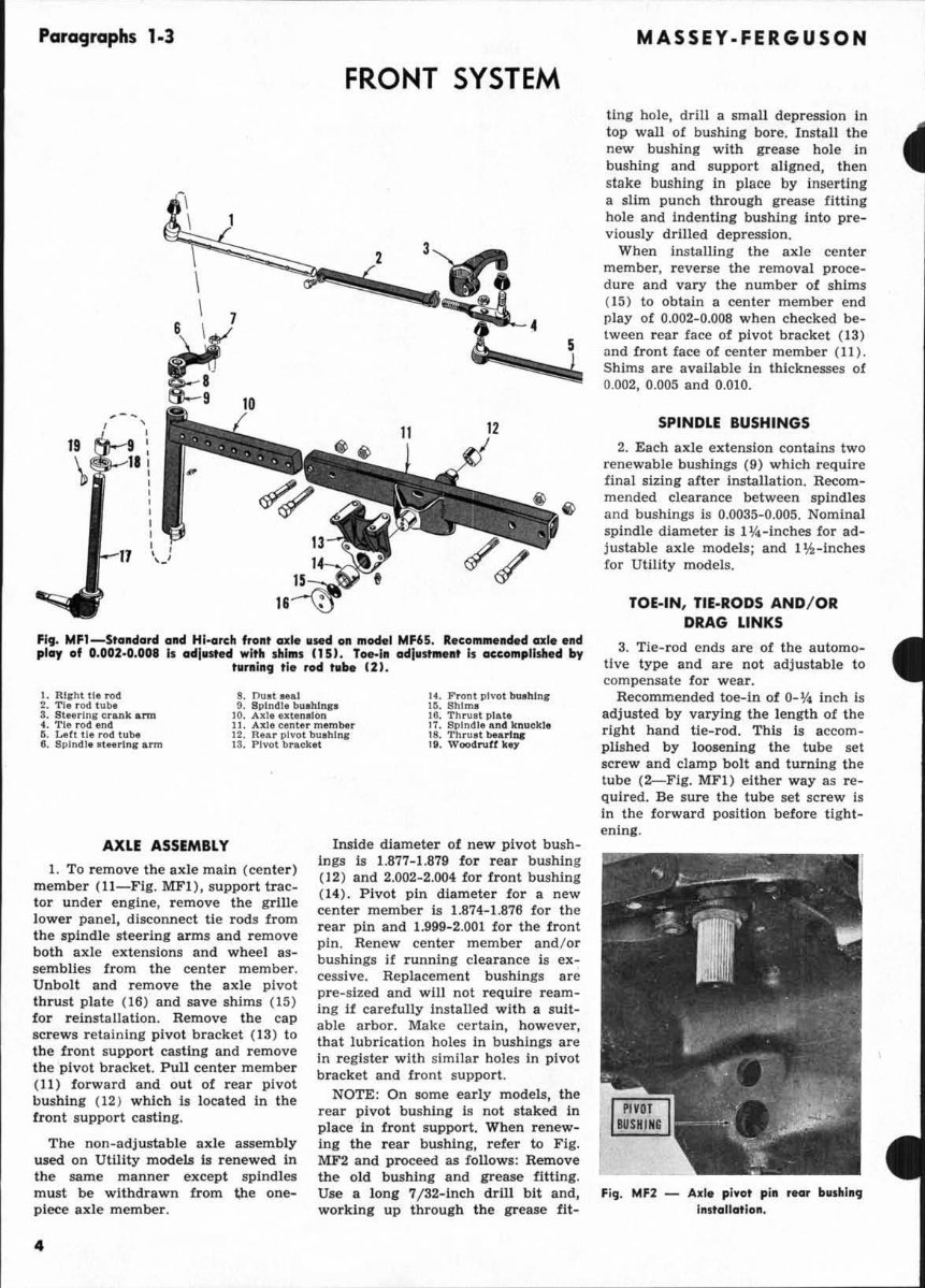
Para9rophs 1-3 FRONT SYSTEM 2 --, 19 F19. MF1-StoJldo,d altd HI-arch fTc"t axle all lIIodel MF6S. Recommended cn:1e li nd play of 0. 002·0 ,Q08 Is adilisted wi th plllls 1151 . Toe- ill adlu, '_nt I, accompllJh. d by tllfllin9 t l. rod hlbe 12 1. 8. Ou.t Hal 14 . Front pivot bUlllln. I. RlIIII Ita rod TI. rod tube 9. Spindle b ... III .... 15. SlIlma 3. Steerlnl c ... nk arm 10. Axl-. uten.lon 16. TII ... ,t pi .. " 4. Ti e rod end 11. A"laeentermembu 17. 8pln<ll. and knuckl. 5. Lett U. rod tlltHo 12. Rea. pivot bu.llln. 18. 'J'hru,t Ma rl ... II. WOOdruff kO 6. Spindle at.,rlnl .. rm 13. Pivot bracke t AXLE ASSEMBLY I. To remove the axle main (ce nter) member (II-Fig. MFI), support trac _ tor under engine, remove the grille l ower panel, disconnect tie rods from the spindle steering arms and remove both axle extensions and wheel as- semblies from the center member. Unbolt and remove the axle pivot thr ust plate (16) and save shims ( 15 ) for relnstaUation. Remove the cap screws retaining pivot bracket (13) to the front support casting and remove the pivot bracket. Pull center member (11) forward and out of rear pivot bushing (12) which Is located in the front support casting. The non-adj ustable axle assemb ly used on Utility models Is renewed In the same manne r except spindles must be wit hdr awn from the one- piece axle member. • Inside diameter ot new pivot bush- ings is 1.877-1.879 for rear bushing (12) and 2.002-2.004 for fr ont bushing (14). Pivot pin diameter for a new center member is 1.874-1.876 for the rear pin and 1.999-2.001 for the front pin. Renew center member and /o r bushings if running clearance is ex- cessive. Replacement bushings are pre-sized and will not require ream- ing It carefully Installed with a suit- able arbor. Make certain, h owever, that lubrication holes In bushings are in register with similar holes in pivot bracket and front support. NOTE: On some early models, the rear pivot bushing Is not staked In pl ace In front support. When renew- Ing the rear bushing, refer to Fig. MF2 and proceed as follows: Remove the old bwhlng and grease fitUng. Use a l ong 7/32-inch drW bit and, working up thr oug h the grease flt- MASSEY-FERGUSON ting hole, drill a small depression In top wall of bushing bore. Install the new bushing with grease hole in bushing and support aligned, then stake bushing in place by jngertlng a slim punch through grease fitting hole and indenting bushing Into pre- viously drilled depression. When Installing the axle center member, reverse the removal proce- dure and vary the number of shims (15) to obtain a center member end play of 0.002-0.008 when checked be- tween rear face of pivot bracket ( 13) Dnd Iront face of center member (11 ). Shims are available in thicknesses of 0.00 2, 0.005 and 0.010. SPINDLE BUSHINGS 2. Each a xle extension contains two renewable bushings ( 9) which require final sizing alter installation. Recom- mended clearance between spind les and bushings is 0.0035-0.005. Nominal sp indle diameter is 1 %-inches for ad- justable axle models; and 11k-Inches for Utility models. TOE. IN, TIE-RODS AND/ OR DRAG LINKS 3. Tie-rod ends are of the automo- tive type and are not adjustable to compensate for wear. Recommended toe-In 01 0- if. inch Is adjusted by varying the len gth of the right hand tie-rod. This is accom- plished by loosening the tube set screw and clamp bolt and turning the tube (2- Flg. MFl) either way as re- quired. Be sure the tube set screw is In the f orward position before tight- ening. Fig. MF2 - 1. .1. pi, ot pin rear bUlhl_ , Inlt o ll ot ion .
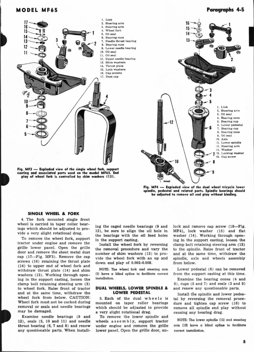
MODEL MF65 1. Unk 2. 8t .. rilll ...... 3. 8t .. rllll · .... ... WhM' fork S.0I1 ... 1 •. IM.rllIlJ r .. .,. 1. N...u. tbrun Marlna: t. 8M., ... rao. I. Lowu MMIII 10. on Ral 11. on ... , UII"'''' ,,_I. bearlll ll II. ShIm ........... It . Tt" .... at plal<o 15. Locll ... II. 17. Dull,.., Fig. MF) - Ex p lodH view of til •• 1191e WNfl forll. SIIppMt c_hll l oM _kited port. 11* .a tM .... M"5 . bel ploy of w,,", fork I. COllftol11tf11 by sill", ..... ,. 0). 16 15 Pa""Jl'GPhs 4-5 I. J.lnll 2. 8t .. rinr arm 3.011 ... 1 t. S.arl ... oou n.arl ... eup S. Lower pM .. t al '. n.anar eup •. a..nnr ....... 8.011 .. al 10. Alli. ' :. Lo ... 13 . StHrt,. am> 14. WaatM.. 1 15 . IACkl'" ...... IM. \: 1 1. Cap ..,raw FI,. Mf.4 - &plo4H " .. .., of tho 4.en ..,_1 tricyc:l. 10..,.' spIN", pH" hll 01111 , elot" ,.m. Spilld .. bowl.,. "011111 be oIIiwstoci to '_0'" 011 tIId ploy ..,ltholFt billdl.,. SINGlE WHEIL & fORK 4. Th e fork mounted s ingle front wheel II car ri ed In taper roll er bear- in,. which shou ld be adjusted to pro- vide a very ,Ught rotati ona l drag, To remove the wheel f ork, support tractor under engine and remove the grill e lower panel. Open the irille door and remove the .heet me tal dust cap (1 7- FiJ . MF3). Remove the cap screws (I6) r eLlinini the thrult plate ( 14 ) to upper end of wheel fork and withdraw thrust plate (14) and shim washen (13). Workin, throu,h open - in, in the s upport casUn,. loose n th e clamp bolt retaining s teerln, arm (3) to wheel fork. Ralse front of tracto r and at the same time, withdraw the wheel fork fr om below. CAUTION: Wheel fork must not be cocked dU r ing removal or seals and need le bearln,s may be damaled. E xami ne needle bearln,s (9 and 12), s eals (:I , 10 and 11 ) and n eedle thrust b ea rln, (6, 7 a nd 8) and r enew any ques ti o nabl e parts. When InstaU- In, the caged needle bearin,. (9 a nd 12 ), be . ur e to aU,n the a ll hol e In tbe bearin,. with the 011 f eed hole l In the support cas tin K. In.tall the wheel fork by r eveni ng the removal procedure and vary the number of s him wa.hen (13) to pro- vide the wheel fork wi th an up and do wn e nd play of 0.002-0.008. NOTE: Tho wh .. 1 'ork and at_rln<j1 arm (3) ba .... a bllnd ,pUn. 10 IodUkllo ecm.a m..-toJkrtioD. DUAL WHIELS, LOWER SPINDLE & LOWER PEDIST AL 5. Each of the dua l whee l. I, mount ed on taper roller bearln,s which sb ould be 10 provide a very sli gh t rot a tiona l dral. To remove the l owe r spindle and wheels ass e m b 1 y, s upport tractor under en,ine and remove t he , rill e lower panel. Open the g rill e door, un- l ock and remove cap screw ( IS-Fig . MF4), lock washer (15) and flat washer (1 4). Working thr ough open- Ing in the support casUng, loosen the clamp bolt retaining steer ing a rm (13) to the spindle. Raise front of tractor and at the same time, withdraw the spindle, axle and wheels assembly from below. Lower pedestal (6) can be remo ved from the su pport casting at thls time. Examine the bearing cones (4 and 8). cups (5 and 7) and seals (3 and 9) and renew any questionable parts . Install tne spindle and lower pedes- tal by reversing the removal proce- dure and U, h len ca p screw (18) to remove all spindle end play without ca usln, any bearing drag. NOTE: Th. lowor 'piDdlo (12) and al .. rlDq 0.1111 U 31 hcrn a blind 'pllDo \0 'odlll<rt. CClrr.CI irullaliatloD. 5
These comprehensive manuals for the Massey Ferguson MF 65 tractor are essential resources for repairing, maintaining, and replacing parts. They are equipped with detailed diagrams and manufacturer specifications, making them valuable for both professional mechanics and DIY enthusiasts.
The navigation is user-friendly, featuring convenient chapter bookmarks and the ability to search by keyword. The manuals are easy to read and can be viewed, zoomed, and printed on any computer. They are also bookmarked, searchable, and indexed for effortless access to the required information.
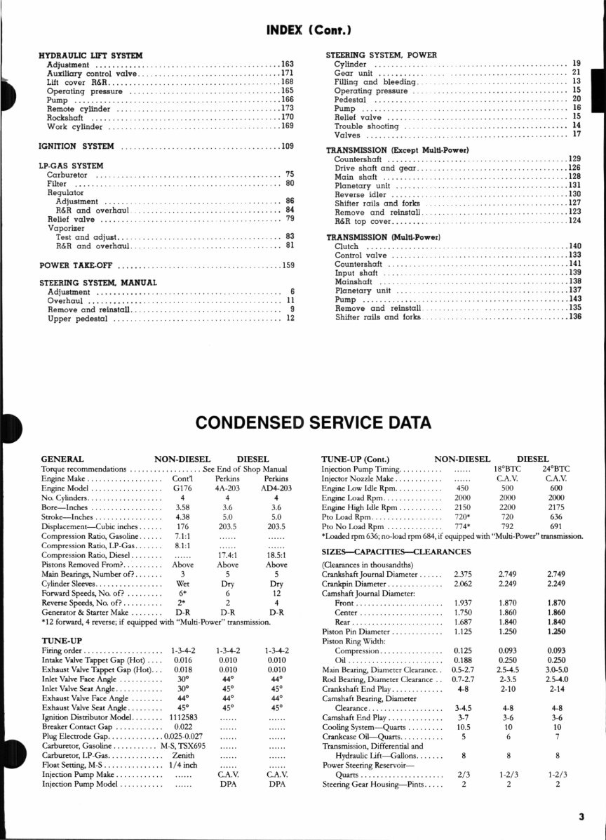
The Service Manual includes sections such as Belt Pulley, Brakes, Carburetor, Clutch, Cooling System, Diesel Fuel System, Differential, Differential Lock, Electrical, Engine, Final Drive, Front Axle, Governor (Non-Diesel), Hydraulic Lift System, Ignition System, Power Take-Off, Service Data, Steering System, and Transmission.
Meanwhile, the Parts Manual comprises sections for Forward, MF 65 Gas Tractor, MF 65 Direct Injection Diesel Tractor, MF 65 Regular Diesel Tractor, Group Index (Gas & LP), Group Index (Diesel), Group Index (Accessories), C.A.V. Service Stations, Numerical Index (Perkins Numbers), Numerical Index (MF Numbers), and Illustrated Parts Lists.
These manuals feature detailed illustrations, exploded diagrams, drawings, and photos to assist users through the service repair procedures. They are completely indexed, bookmarked, and searchable, making them ideal for tune-ups, regular maintenance, or repairs. The technical details and step-by-step instructions provided are comprehensive and invaluable.
For immediate access to these manuals, simply click the provided button. Please note that the documents may require the latest version of Acrobat Reader for optimal display. If you encounter any issues, consider upgrading to the newest version of Adobe Acrobat Reader. For any additional manual needs, feel free to email us, as we have a vast collection of manuals available.
Recently Viewed
5,521,897Happy Clients
2,594,462eManuals
1,120,453Trusted Sellers
15Years in Business
Price:
Actual Price:
Massey Ferguson MF 65 Tractor Service Manual & Parts Manual -2- Manuals -