

Massey Ferguson 50 & 65 Tractor Service & Repair Manual
What's Included?
Fast Download Speeds
Online & Offline Access
Access PDF Contents & Bookmarks
Full Search Facility
Print one or all pages of your manual
MASSEY -FERGUSON
GROUP IV - SECTION A - PART 2
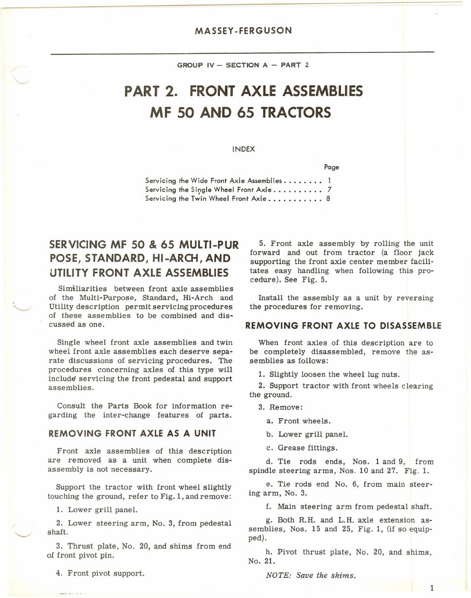
PART2. FRONT AXLE ASSEMBLIES
MF 50 AND 65 TRACTORS
INDEX
Page
Servicing the Wide FrontAxle Assemblies. . . . . . .. 1
Servicing the Si~gle Wheel Front Axle. ......... 7
Servicing the TwinWheel Front Axle........... 8
SERVICINGMF 50 &65 MULTI-PUR
POSE, STANDARD, HI-ARCH,AND
UTILITY FRONT AXLE ASSEMBLIES
Similiarities between front axle assemblies
of the Multi-Purpose, Standard, Hi-Arch and
Utility description permit servicing procedures
of these assemblies to be combined and dis-
cussed as one.
Single wheel front axle assemblies and twin
wheel front axle assemblies each deserve sepa-
rate discussions of servicing procedures. The
procedures concerning axles of this type will
include servicing the front pedestal and support
assemblies.
Consult the Parts Book for information re-
garding the inter-change features of parts.
REMOVING FRONT AXLE AS A UNIT
Front axle assemblies of this description
are removed as a unit when complete dis-
assembly is not necessary.
Support the tractor with front wheel slightly
touching the ground, refer to Fig. 1, and remove:
1. Lower grill panel.
2. Lower steering arm, No.3, from pedestal
shaft.
3. Thrust plate, No. 20, and shims from end
of front pivot pin.
4. Front pivot support.
5. Front axle assembly by rolling the unit
forward and out from tractor (a floor jack
supporting the front axle center member facili-
tates easy handling when following this pro-
cedure). See Fig. 5.
Install the assembly as a unit by reversing
the procedures for removing.
REMOVING FRONT AXLE TO DISASSEMBLE
When front axles of this description are to
be completely disassembled, remove the as-
semblies as follows:
1. Slightly loosen the wheel lug nuts.
2. Support tractor with front wheels clearing
the ground.
3. . Remove:
a. Front wheels.
b. Lower grill panel.
c. Grease fittings.
d. Tie rods ends, Nos. 1 and 9, from
spindle steering arms, Nos. 10 and 27. Fig. 1.
e. Tie rods end No.6, from main steer-
ing arm, No.3.
f. Main steering arm from pedestal shaft.
g. Both R.H. and L.H. axle extension as-
semblies, Nos. 15 and 25, Fig. 1, (if so equip-
ped).
h. Pivot thrust plate, No. 20, and shims,
No. 21.
NOTE: Save the shims.
1
MASSEY -FERGUSON
FRONT AXL E & STEERING
GROUP IV - SECTION A- PART 2
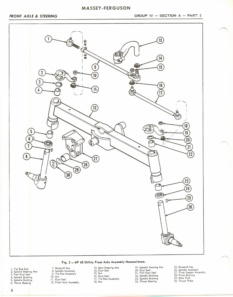
Fig. 3 _ MF 65 Utility Front Axle Assembly Nomenclature.
1. Tie Rod End
2. Spindle Steering Arm
3. Felt Dust Seol
4. Spindle Bushing
5. Spindle Bushing
6. Thrust Bearing
7. Woodruff Key
8. Spindle Assembly
9. Tie Rod Assembly
10. Nut
11. Dust Seal
12. Front Axle Assembly
13. Main Steering Arm
14. Dust Seal
15. Nut
16. Dust Seal
17. Tie Rod Assembly
18. Nut
19. Spindle Steering Arm
20. Dust Seal
21. Felt Dust Seal
22. Spindle Bushing
23. Spindle Bushing
24. Thrust Bearing
25. Woodruff Key
26. Spindle Assembly
27. Pivot Support Assembly
28. Pivot Bushing
29. Shim Pock
30. Thrust Plate
4
GROUP IV - SECTION A - PART 2
MASSEY -FERGUSON
MF 50 & 65 FRONT AXLE & STEERING
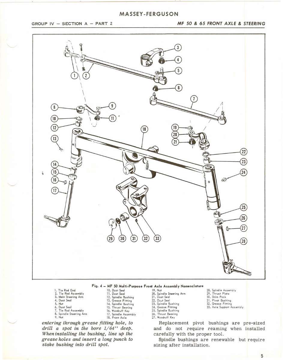
1. Tie Rod End
2. Tie Rod Assembly
3. Main Steering Arm
4. DustSeal
5. Nut
6. DustSeal
7. Tie RodAssembly
8. SpindleSteeringArm
9. Nut
Fig. 4 - MF 50 Multi-Purpose Front Axle Assembly Nomenclature
10. Dust Seal 19. Nut
11. Dust Seal 20. Spindle Steering Arm
12. Spindle Bushing 21. Dust Seal
13. Grease Fitting 22. Du..t Seal
14. Spindle Bushing 23. Spindle Bushing
15. Thrust Bearing 24. Grease Fitting
16. WoodruffKey 25. Spindle Bushing
17. Spindle Assembly 26. Thrust Bearing
18. Front Axle 27. WoodruffKey
28. Spindle Assembly
29. Thrust Plate
30. Shim Pock
31. Pivot Bushing
32. Grease Fitting
33. Axle Support Assembly
entering through grease fitting hole, to
drill a spot in the bore 1/64" deep.
When installing the bushing, line up the
grease holes and insert a long punch to
stake bushing into drill spot.
Replacement pivot bushings are pre-sized
and do not require reaming when installed
carefully with the proper tool.
Spindle bu~hings are renewable but require
sizing after installation.
5
FRONT AXLE & STEERING
MASSEY -FERGUSON
GROUP IV - SECTION A - PART 2
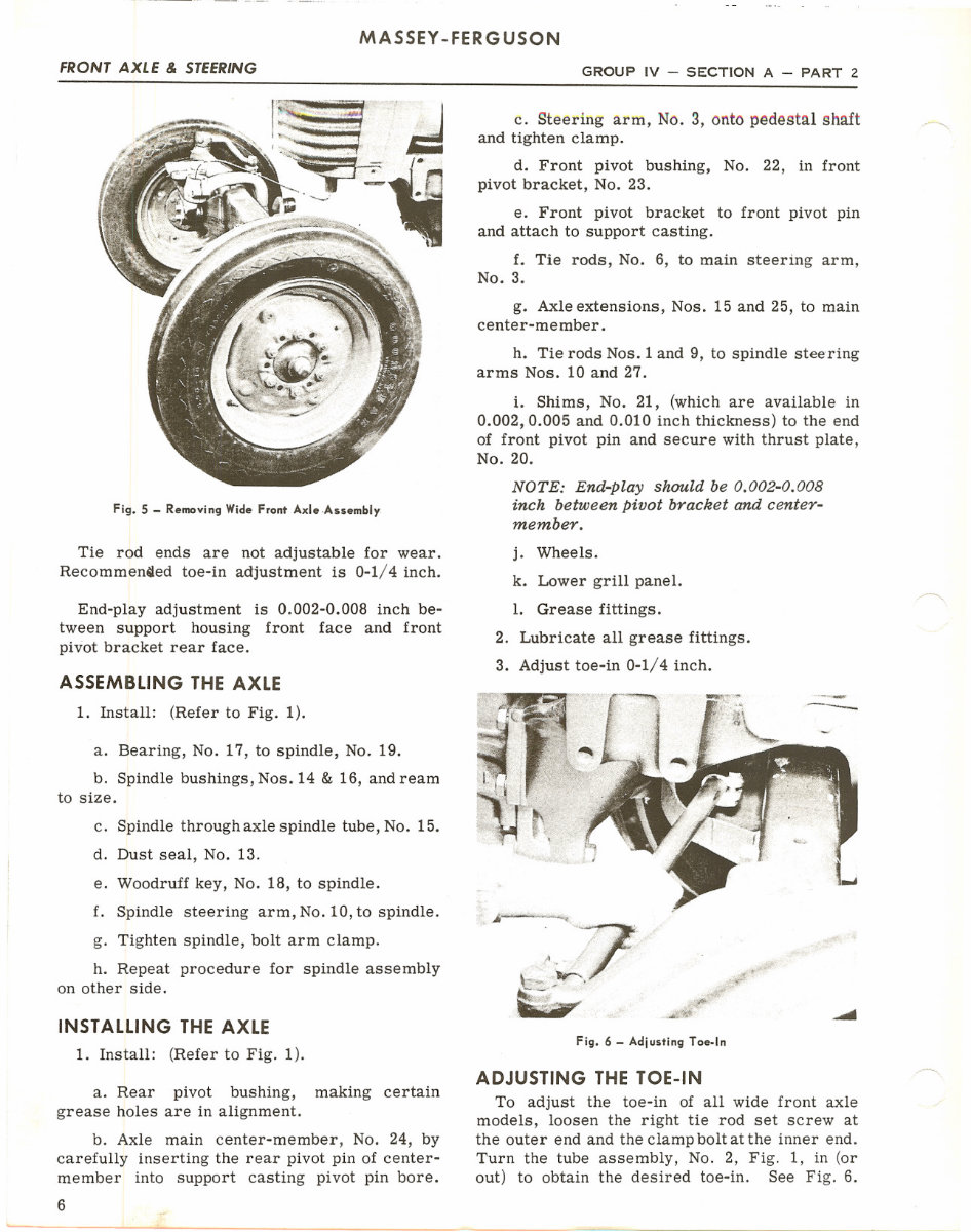
Fig. 5 - Removing Wide Front Axle.Assembly.
Tie rod ends are not adjustable for wear.
Recommen~ed toe-in adjustment is 0-1/4 inch.
End-play adjustment is 0.002-0.008 inch be-
tween support housing front face and front
pivot bracket rear face.
ASSEMBLING THE AXLE
1. Install: (Refer to Fig. 1).
a. Bearing, No. 17, to spindle, No. 19.
b. Spindle bushings, Nos. 14 & 16, and ream
to size.
c. Spindle through axle spindle tube, No. 15.
d. Dust seal, No. 13.
e. Woodruff key, No. 18, to spindle.
f. Spindle steering arm, No. 10, to spindle.
g. Tighten spindle, bolt arm clamp.
h. Repeat procedure for spindle assembly
on other side.
INSTALLING THE AXLE
1. Install: (Refer to Fig. 1).
a. Rear pivot bushing, making certain
grease holes are in alignment.
b. Axle main center-member, No. 24, by
carefully inserting the rear pivot pin of center-
member into support casting pivot pin bore.
6
c. Steering arm, No.3, onto pedestal shaft
and tighten clamp.
d. Front pivot bushing, No. 22, in front
pivot bracket, No. 23.
e. Front pivot bracket to front pivot pin
and attach to support casting.
f. Tie rods, No.6, to main steering arm,
No.3.
g. Axle extensions, Nos. 15 and 25, to main
center-member.
h. Tie rods Nos. 1 and 9, to spindle stee-ring
arms Nos. 10 and 27.
i. Shims, No. 21, (which are available in
0.002,0.005 and 0.010 inch thickness) to the end
of front pivot pin and secure with thrust plate,
No. 20.
NOTE: End-Play shuuld be 0.002-0.008
inch between Pivot bracket and center-
member.
j. Wheels.
k. Lower grill panel.
1. Grease fittings.
2. Lubricate all grease fittings.
3. Adjust toe-in 0-1/4 inch.
....
~_~7
~
.
Fig. 6 - Adjusting Toe-In
ADJUSTING THE TOE-IN
To adjust the toe-in of all wide front axle
models, loosen the right tie rod set screw at
the outer end and the clamp bolt at the inner end.
Turn the tube assembly, No.2, Fig. 1, in (or
out) to obtain the desired toe-in. See Fig. 6.
GROUP IV - SECTION A - PART 2
MASSEY-FERGUSON
MF 50 & 65 FRONT AXLE & STEERING
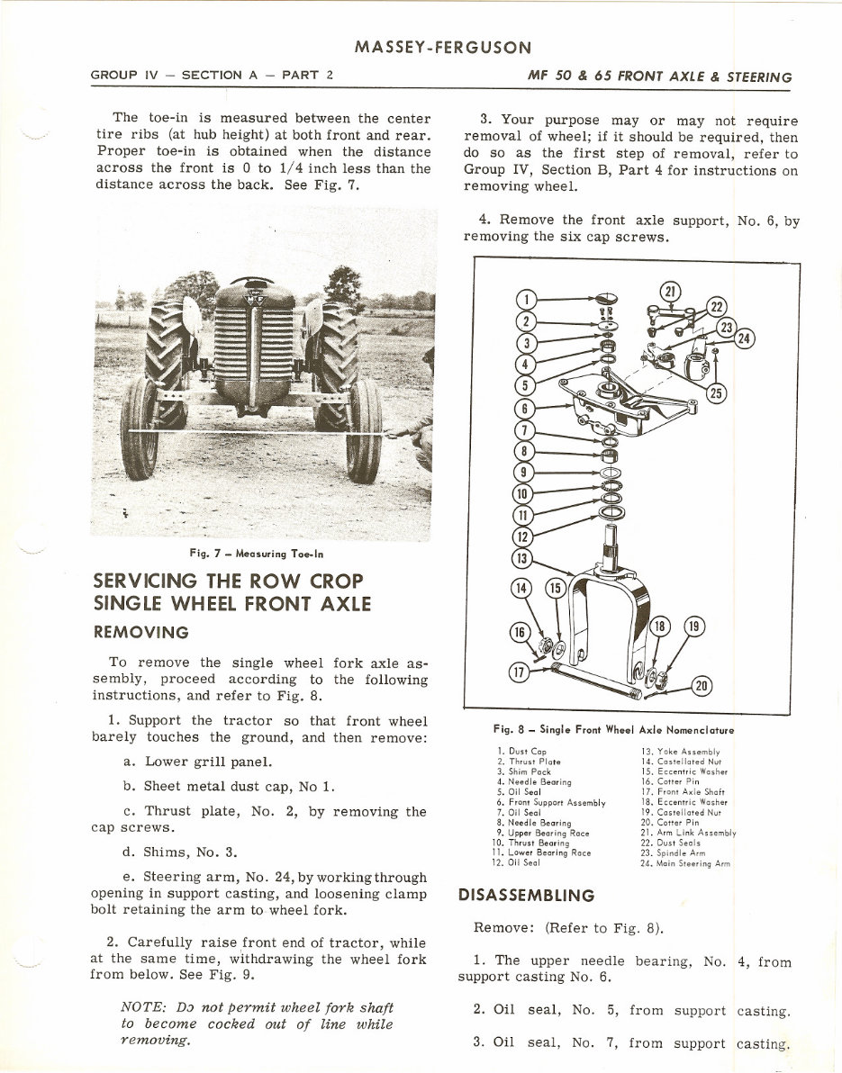
The toe-in is measured between the center
tire ribs (at hub height) at both front and rear.
Proper toe-in is obtained when the distance
across the front is 0 to 1/4 inch less than the
distance across the back. See Fig. 7.
Fig. 7 - Measuring Toe-In
SERVICING THE ROW CROP
SINGLE WHEEL FRONT AXLE
REMOVING
To remove the single wheel fork axle as-
sembly, proceed according to the following
instructions, and refer to Fig. 8.
1. Support the tractor so that front wheel
barely touches the ground, and then remove:
a. Lower grill panel.
b. Sheet metal dust cap, No 1.
c. Thrust plate, No.2, by removing the
cap screws.
d. Shims, No.3.
e. Steering arm, No. 24, by working through
opening in support casting, and loosening clamp
bolt retaining the arm to wheel fork.
2. Carefully raise front end of tractor, while
at the same time, withdrawing the wheel fork
from below. See Fig. 9.
NOTE: D:J not permit wheel fork shaft
to become cocked out of line while
removing.
3. Your purpose mayor may not require
removal of wheel; if it should be required, then
do so as the first step of removal, refer to
Group IV, Section B, Part 4 for instructions on
removing wheel.
4. Remove the front axle support, No.6, by
removing the six cap screws.
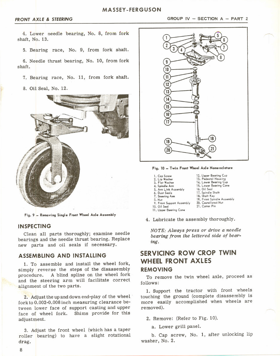
Fig. 8 - Single Front WheelAxle Nomenclature
1. Dust Cap
2. Thrust Plate
3. Shim Pack
4. Needle Bearing
5. Oil Seal
6. Front Support Assembly
7. Oil Seal
8. Needle Bearing
9. Upper Bearing Race
10. Thrust Bearing
11. Lower Bearing Race
12. Oil Seal
13. Yoke Assembly
14. Castellated Nut
15. Eccentric Washer
16. Cotter Pin
17. Front Axle Shaft
18. Eccentric Washer
19. Castellated Nut
20. Cotter Pin
21. Arm Link Assembly
22. Dust Seals
23. Spindle Arm
24. Main Steering Arm
DISASSEMBLING
Remove: (Refer to Fig. 8).
1. The upper needle bearing, No.4, from
support casting No.6.
2. Oil seal, No.5, from support casting.
3. Oil seal, No.7, from support casting.
FRONT AXLE & STEERING
MASSEY -FERGUSON
GROUP IV - SECTION A - PART 2
4. Lower needle bearing, No.8, from fork
shalt, No. 13.
5. Bearing race, No.9, from fork shaft.
6. Needle thrust bearing, No. 10, from fork
shaft.
7. Bearing race, No. 11, from fork shaft.
8. Oil Seal, No. 12.
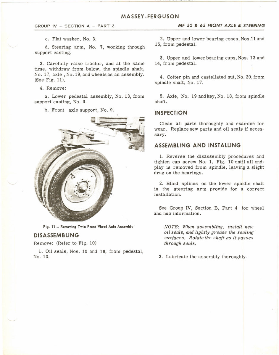
Fig. 9 - RemovingSingle Front Wheel Axle Assembly
INSPECTING
Clean all parts thoroughly; examine needle
bearings and the needle thrust bearing. Replace
new parts and oil seals if necessary.
ASSEMBLING AND INSTALLING
1. To assemble and install the wheel fork,
simply reverse the steps of the disassembly
procedure. A blind spline on the wheel fork
and the steering arm will facilitate correct
alignment of the two parts.
2. Adjust the up and down end-play of the wheel.
fork to 0.002-0.008 inch measuring clearance be-
tween lower face of support casting and upper
face of wheel fork. Shims provide for this
adjustment.
3. Adjust the front wheel (which has a taper
roller bearing) to have a slight rotational
drag.
8
Fig. 10 - Twin Front Wheel Axle Nomenclature
1. Cap Screw
2. Lip Washer
3. Flat Washer
4. Spindle Arm
5. Arm Link Assembly
6. Dust Seals
7. Steering Arm
D. Nut
9. Front Support Assembly
10. Oil Seal
11. Upper Bearing Cone
12. Upper Bearing Cup
13. Pedestal Housing
14. Lower Bearing Cup
15. Lower Bearing Cone
16. Oil Seal
17. Spindle Shalt
18. Shalt Key
19. Front Spindle Assembly
20. Castellated Nut
21. Cotter Pin
4. Lubricate the assembly thoroughly.
NOTE: Always press or drive a needle
bearing from the lettered side of bear-
ing.
SERVICING ROW CROP TWIN
WHEEL FRONT AXLES
REMOVING
To remove the twin wheel axle, proceed as
follows:
1. Support the tractor with front wheels
touching the ground (complete disassembly is
more easily accomplished when wheels are
removed).
2. Remove: (Refer to Fig. 10).
a. Lower grill panel.
b. Cap screw, No.1, after unlocking lip
washer, No.2.
GROUP IV - SECTION A - PART 2
MASSEY -FERGUSON
MF 50 & 65 FRONT AXLE & STEERING
c. Flat washer, No.3.
d. Steering arm, No.7, working through
support casting.
3. Carefully raise tractor, and at the same
time, withdraw from below, the spindle shaft,
No. 17, axle ,No. 19, and wheels as an assembly.
(See Fig. 11).
4. Remove:
a. Lower pedestal assembly, No. 13, from
support casting, No.9.
b. Front axle support, No.9.
Fig. 11 - RemovingTwin Front Wheel Axle Assembly
DISASSEMBLING
Remove: (Refer to Fig. 10)
1. Oil seals, Nos. 10 and 16, from pedestal,
No. 13.
2. Upper and lower bearing cones, Nos.11 and
15, from pedestal.
3. Upper and lower bearing cups, Nos. 12 and
14, from pedestal.
4. Cotter pin and castellated nut, No. 20, from
spindle shaft, No. 17.
5. Axle, No. 19 and key, No. 18, from spindle
shaft.
INSPECTION
Clean all parts thoroughly and examine for
wear. Replace new parts and oil seals if neces-
sary.
ASSEMBLING AND INSTALLING
1. Reverse the disassembly procedures and
tighten cap screw No.1, Fig. 10 until all end-
play is removed from spindle, leaving a slight
drag on the bearings.
2. Blind splines on the lower spindle shaft
in the steering arm provide for a correct
installation.
See Group IV, Section B, Part 4 for wheel
and hub information.
NOTE: When assembling, install new
oil seals, and lightly grease the sealing
surfaces. Rotate the shaft as it passes
through seals.
3. Lubricate the assembly thoroughly.


,
You're Reading a Preview
What's Included?
Fast Download Speeds
Online & Offline Access
Access PDF Contents & Bookmarks
Full Search Facility
Print one or all pages of your manual
$37.99
Viewed 12 Times Today


Secure transaction
What's Included?
Fast Download Speeds
Online & Offline Access
Access PDF Contents & Bookmarks
Full Search Facility
Print one or all pages of your manual
$37.99
Massey Ferguson 50 & 65 Tractor Service & Repair Manual is a comprehensive resource that includes:
- General info and service tools
- Maintenance, hydraulics and linkage
- Troubleshooting
- Engine, G-176, GB176, 4A203, AD4203 ENGINES, GAS AND DIESEL
- Transmission including multipower and dual clutch info
- Fuel system and carb
- Lubrication system
- Electrical system and magneto
- Valve adjustment
- Steering system, front end standard hi-arch & utility front axle
- Suspension/brakes/ pto shaft assembly, diff and rear axle
- Body/fenders/lights and implements
- Over 360 pages of essential information
This manual is a valuable resource for both professional mechanics and DIY enthusiasts.


