

Massey Ferguson MF365 Tractor OEM Service & Repair Manual
What's Included?
Fast Download Speeds
Online & Offline Access
Access PDF Contents & Bookmarks
Full Search Facility
Print one or all pages of your manual

Masse
y
hr3uson
300 Series
Tractor
Workshop Manual
Publication No 1856 558 MS
Published by:
Mass Ferguson (United Kingd) Limited,
Banner Lane,
Covent
CV4 9GF

Published by:
300 SERIES TRACR RHOP MANUAL
•
•
Stion No
1
2
3
4
5
6
7
8
I
Publication No 1856 558 MB
CONTENTS
Description
INTRODUCTION ANO SAFE
SPECIFICATIONS
SPLIING THE TRACTOR - CAB MODELS
ENGINE D
COOLING SYSTEM
FUEL AND AIR SYSTEM
CLUTCHES
GEARBOXES
REAR AXLE, BRAKES AND DIFFERENTIAL
Mass Ferguson (Unit Kingd) Limited,
Banner Lane,
Covent
CV49GF
Fgu a w su ol 1 AGCO pu@ion
300 SERIES TRACTOR WORKSHOP MANUAL
First edition 1986
Second edition 1987
Third edition 1988
Fourth edition 1989
Fifth edition 1990
Sixth edition 1991
Seventh edition 1994
Eighth edition 1996
Published by:
Massey Ferguson (United Kingdom) Limited,
Banner Lane.
Coventry
CV49GF
Massey Ferguson is a wholly owned subsidiary 01 tne AGeD Corporation
1
INTRODUCTION AND SAFETY
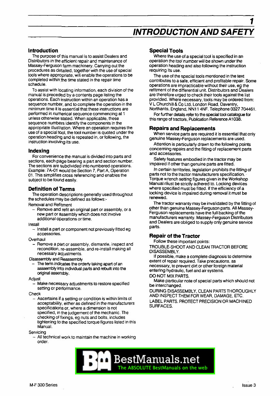
Introduction
The purpose of this manual is to assist Dealers and
Distributors in the efficient repair and maintenance of
Massey-Ferguson farm machinery. Carrying out the
procedures as delailed, together with the use of special
tools where appropriate, will enable the operations to be
completed withinJhe time stated in the repair time
schedule.
To assist with locating information, each division of the
manual is precedM by a contents page listing the
operations. Each instruction within an operation has a
sequence number, and to complete the operation in the
minimum time it is essential that these instructions are
performed in numerical sequence commencing at 1
unless otherwise stated. When applicable, these
sequence numbers identify the components in the
appropriate illustration. Where an operation requires the
use of a special tOOl, the tool number is quoted under the
operation heading and is repeated in, or following, the
instruction involving its use.
Indexing
For convenience the manual is divided into parts and
sections, each page bearing a part and section number.
The sections are $ubdivided into numbered operations.
Example: 7A-01 would be Section 7, Part A, Operation
01. This simplifies cross referencing and enables the
subject to be found easily.
Definition of Terms
The operation Clescriptions generally used throughout
the schedules may be defined as follows:-
Removal and Refitment
- Remove and refit an original part or assembly, or a
new part or assembly which does not involve
additional operations or time.
Install
- Install a part or component not previously fitted eg
accessories.
Overhaul
- Remove a part or assembly, dismantle, inspect and
recondition, re-assemble, and re-install making all
necessary adjustments.
Disassembly and Reassembly
- The term indicates the orderly taking apart of an
asssembly into indMduai parts and into the
original assembly.
Adjust
- Make necessary adjustments to restore specified
setting or performance.
Check
- Ascertains if a setting or condition is within limits of
acceptability, either as defined in the manufacturers
specifications or, wihere a dimension is not
specified, in the judgement of the mechanic. The
checking of fixings, eg nuts and bolts, includes
tightening to the specified torque figures listed in this
Manual.
Servicing
- All technical work to maintain the machine in working
order.
M-F 300 Series
Special Tools
Where the use of a special tool is specified in an
operation the tool number will be shown under the
operation heading and also following the instruction
requiring its use.
The use of the special tools mentioned in the text
contributes to a safe, efficient and profitable repair. Some
operations are impracticable without their use, eg the
refitment of the differential unit. Distributors and Dealers
are therefore urged to check their tools against the list
provided. Where necessary, tools may be ordered from:
V L Churchill & Co Ltd, London Road, Daventry,
Northants, England, NN11 4NF. Telephone 0327 704461.
For further details refer to the special tool catalogue for
this range of tractorS, Publication Reference A1038.
Repairs and Replacements
When service parts are required it is essential that only
genuine Massey-Ferguson replacements are used.
Attention is particularly drawn to the following points
concerning repairs and the fitting of replacement parts
and accessories.
Safety features embodied in the tractor may be
impaired if other than genuine parts are fitted.
In cerfain territories, legislation prohibits the fitting of
parts not to the tractor manufacturers specification ..
Torque wrench setting figures given in the Workshop
Manual rilust be strictly adhered to. Locking devices
wihere specified must be fitted. If the efficiency of a
locking device is impaired during removal it must be
renewed.
The tractor warranty may be invalidated by the fitting of
other than genuine Massey-Ferguson parts. All Massey-
Ferguson replacements have the full backing of the
manufacturers warranty. Massey-Ferguson Distributors
and Dealers are obliged to supply only genuine service
parts.
Repair of the Tractor
Follow these important points:
TROUBLE-SHOOT AND CLEAN TRACTOR BEFORE
DISASSEMBLY.
If possible, make a complete diagnosis to determine
extent of repair required. Take precautions, as
necessary, to prevent dirt or other foreign material
entering hydraulic, fuel and air systems.
DO NOT MIX PARTS.
Make particular note of special parts which should not
be interchanged.
DURING DISASSEMBLY, CLEAN PARTS THOROUGHLY
AND INSPECT THEM FOR WEAR, DAMAGE, ETC.
LABEL PARTS. PROTECT PRECISION OR MACHINED
SURFACES.
Issue 3
2 _.
ilNTRODUCTION AND SAFETY
Repair Time Schedule
The operations listed in the Repair Time Schedule refer
to those descril:led in this manual. The time set against
each operation in the schedule is established by
performing the actual operations on standard machines
using special tools where applicable. The Repair Time
Schedule for use with this manual is issued as a separate
publication.
Note: Repair Time Schedules are issued to Massey·
Ferguson Distributors and Dealers only and are not for
general circulation.
Amendments
Under normal conditions revised pages are issued
canying the same number as the existing pages
requiring amendment. The new pages are inserted in
place of the existing ones. The old pages should then be
destroyed.
The issue number is printed on the bottom of each
page, eg Issue 1,2 or 3 etc.
In some cases aditional pages or completely new
sections may be issued. These pages are to be inserted
immediately following the page carrying the next lowest
page number, or section number as appropriate.
. Where new pages are required to be positioned
between existing pages, the new page numbers will
contain a suffix letter ··Example:· New page number
7A·16a. This page is inserted after existing page number
7A·16 and before page number 7A·17. Correspondingly
a further new page numbered 7 A·16b would be
positioned after 7 A·l6a but before 7A·17.
To ensure that a record of amendments to this manual
is readily available, the list of amendments will be
re-issued with each set of revised pages, quoting the
amendment number, date of issue, appropriate
instrucitons and revised page numbers.
Note: Service Bulletins and Amendment Sheets are
issued to the Massey·Ferguson Distributors and Dealers
only and are not for general circulation. .
A
Safety Precautions
Make sure thai all personnel are in a safe position
before starting the engine, or operating ANY of the
controls.
Always stop the engine before leaving the operator's
platform.
Wait for all moving parts to stop COMPLETELY before
starting any work on the tractor.
Before starting service procedures ... attached
equipment should be resting on the ground and all
hydraulic control levers operated back and forth several
times with the engine stopped.
If it becomes necessary to go under a raised
attachment (eg loader) to perform adjustments etc, safety
stands must be used to support the attachment.
Make sure the battery earth cables are disconnected
before working on the electical system.
M·F 300 Series
Keep hands, feet and clothing a safe distance away
from moving belts, pulleys and other moving parts ...
and make sure all safety shields are installed.
Be extra careful when performing any checks,
inspection, adjustments or tests that require operating
the engine, the hydraulic controls, or with the machine in
motion.
Make sure dependable jacks of adequate lifting
capacity and suitable stands (or wooden blocking) are
used to securely block up the machine when removing
any of the wheels or axles.
Before any attempt is made to disconnect or remove
any hydrauliC component, make sure the hydraulic
pressure within the system is relieved ... and the engine
is stopped.
Carry out the repair procedures in a 'common sense"
manner. Safety procedures cannot be over-emphasised
when working on, or around machinery ... especially
when working on engine driven andlor hydraulically
actuated equipment.
Safety also depends upon the skill of the serviceman in
the use of tools and other workshop equipment while
performing the recommended service procedures.
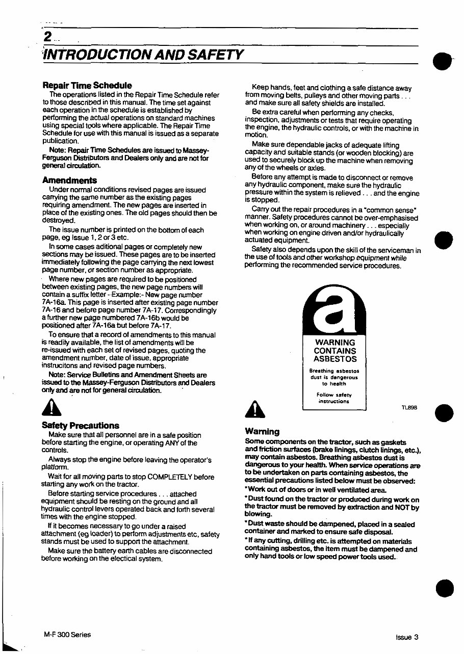
Warning
WARNING
CONTAINS
ASBESTOS
Breathing asbestos
dust is dangerous
to health
Follow safetv
instructions
TL898
Some components on the tractor, such as gaskets
and friction surfaces (brake linings, Clutch Dnings, etc.),
may contain asbestos. Breathing asbestos dust is
dangerous to your health. When service operations are
to be undertaken on parts containing asbestos, the
essential precautions listed below must be observed:
'Work out of doors or in well ventilated area
• Dust found on the tractor or produCed during work on
the tractor must be removed by extraction and NOT by
blOwing.
"Dust waste should be dampened, placed in a sealed
container and marked to ensure safe disposal.
"If any cutting, drilling etc. is attempted on materials
containing asbestos, the item must be dampened and
only hand tools or low speed power tools used •.
Issue 3
e-
•
•
•
3
INTRODUCTION AND SAFETY
Roll Over Protective Structures (ROPS) and/or Safety Frames and Cabs
ALWAYS observe the following
points - these are IMPORTANT.
TIGHTEN ALL BOLTS progressively
and evenly to their recommended
torques.
Install all bolts which project
through inside edges and/or
faces of frames, or cab so that
threaded end of bolt (ie nut
side) is outside frame.
Use only bolts and other
hardware supplied with ROPS
(or cab frame) ... do not
substiMe these fasteners.
Use a flat washer over slotted
holes.
Use lockwasher to secure nuts
... except self-locking type
nut.
DO NOT do any of the following.
Drill the frame structure to
accept equipment such as extra
mirrors or flashing indicators.
Weld anything to the frame.
Straighten a bent frame.
Interchange components with
other frame structures even of
identical type.
Modify the frame structure in
any way without prior approval
of Massey-Ferguson.
Attach other implements, or
fittings to Tractor by means
of the frame structure (or its
attachment points) unless such
attachments are approved by
Massey-Ferguson.
PERSONAL INJURY MAY RESULT IF THESE PRECAUTIONS ARE NOT FOLLOWED.
Look for this symbol to point out important safety precautions. It means - ATTENTION! BECOME ALERT! YOUR
SAFETY IS INVOLVED.
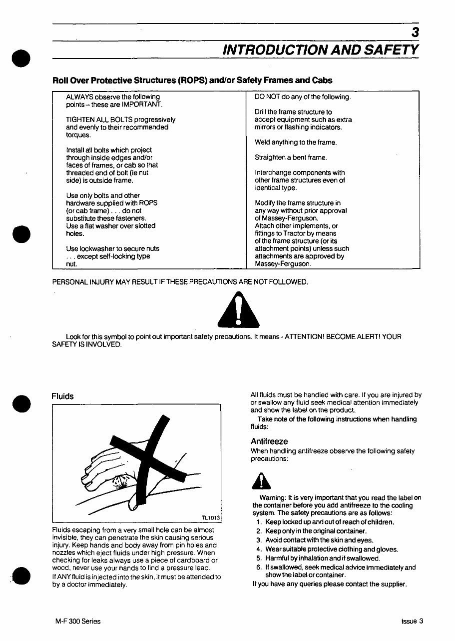
Fluids
Fluids escaping from a very small hole can be almost
invisible, they can penetrate the skin causing serious
injury. Keep hands and body away from pin holes and
nozzles which eject fluids under high pressure. When
checking for leaks always use a piece of cardboard or
wood, never use your hands to find a pressure lead.
If ANY fluid is injected into the skin. it must be attended to
by a doctor immediately.
M-F 300 Series
All fluids must be handled with care. If you are injured by
or swallow any fluid seek medical attention immediately
and show the label on the product.
Take note of the following instructions when handling
fluids:
Antifreeze
When handling antifreeze observe the following safety
precautions:
Warning: It is very important that you read the label on
the container before you add antifreeze to the cooling
system. The safety precautions are as follows:
1. Keep locked up and out of reach of children.
2. Keep only in the original container.
3.
4. protective clothing and gloves.
5. Harmful by inhalation and if swallowed.
6. If swallowed, seek medical advice immediately and
show the label or container.
If you have any queries please contact the supplier.
Issue 3
4
INTRODUCTION AND SAFETY
Engine and transmission oils
Waming: When changing oil is important you follow
some basic rules on personal hygiene, these are as
follows:
1. Before changing the oil use a barrier cream
on your hands
2. Wear protective clothing, overalls, PVC gloves etc.
3. Wash off with soap and water any diny oil which you
come into contact as soon as soon as you have
finished changing the oil.
4. Contaminated clothing must be removed and cleaned.
Prolonged contact with diny oil may affect your health and
is important you follow the above instructions.
TlB94
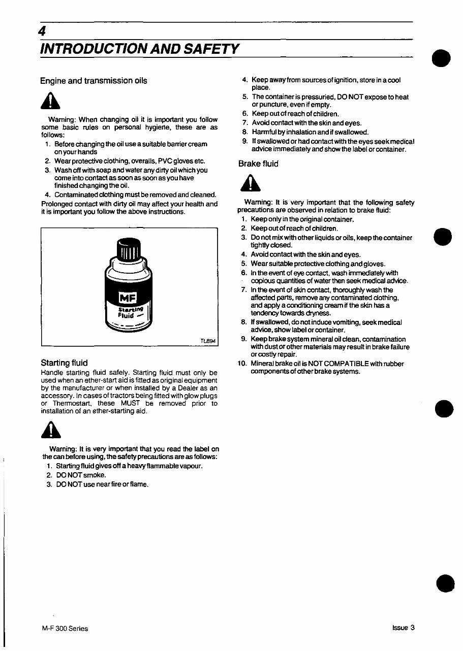
Starting fluid
Handle starting fluid safely. Starting fluid must only be
used when an ether-start aid is fitted as original equipment
by the manufacturer or when installed by a Dealer as an
accessory. In cases oftractors being fitted with glow plugs
or Thermostart, these MUST be removed prior to
installation of an ether-starting aid.
Warning: It is very important that you read the label on
the can before using, the safety precautions are as follows:
1. Startingfiuid gives off a heavy flammable vapour.
2. DO NOT smoke.
3. DO NOT use nearfireorfiame.
M-F 300 Series
4. Keep away from sources of ignition, store in a cool
place.
5. The container is pressuried, DO NOT expose to heat
or puncture, even ij empty.
6. Keep out ot reach of children.
7. Avoid contact the skin and eyes.
8. Hannful by inhalation and ij swallowed.
9. If swallowed or had oontact with the eyes seek medical
advice immediately and show the label or oontainer.
Brake fluid
Warning: It is very important that the following safety
precautions are observed in relation to bralke fluid:
1. Keep only in the original oontainer.
2. Keep out ot reach of children.
3. Do not mix with other liquids or oils, keep the container
tightly closed.
4. Avoid contact with the skin and eyes.
5. Wear protective clothing and gloves.
6. In the event of eye contact, wash immecfl8lely with
oopious quantities of water then seek medical advice.
7. In the event of skin oontact, thoroughly wash the
affected parts, remove any contaminated clothing,
and apply a conditioning cream ij the skin has a
tendency towards dryness.
8. Hswallowed, do not induce vomiting, seek medical
advice, show label oroontainer.
9. Keep brake system mineral oil clean, contamination
with dust or other materials may resutt in brake failure
or costly repair.
10. Mineral brake oil is NOT COMPATIBLE with rubber
oomponents of other brake systems.
Issue 3
•
•
•
•
.'
•
5
INTRODUCTION AND SAFETY
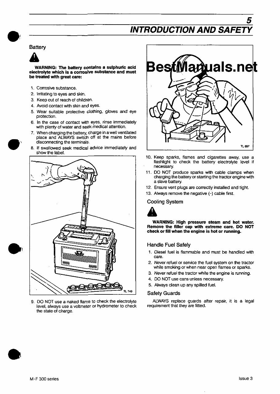
Battery
A
WARNING: The battery contains a sulphuric acid
electrolyte which Is a conosive substance and must
be treated with great care:
1. Corrosive substance.
2. Irritating to eyes and skin.
3. Keep out of reach of children.
4. Avoid contact with skin and eyes.
5. Wear suitable protective clothing, gloves and eye
protection.
6. In the case of contact with eyes, rinse immediately
with plenty of water and seek medical attention.
7. When charging the battery, charge in a well ventilated
place and ALWAYS switch off at the mains before
disconnecting the terminals.
8. If swallowed seek medical advice immediately and
show the label.
9. DO NOT use a naked flame to check the electrolyte
level, always use a vohmeter or hydrometer to check
the state of charge .
M-F 300 series
TL897
10. Keep sparks, flames and Cigarettes away, use a
flashlight to check the battery electrolyte level if
necessary.
11. DO NOT produce sparks with cable clamps when
charging the battery or starting the tractor engine with
a slave battery.
12. Ensure vent plugs are correctly installed and tight.
13. Always remove the negative H cable first.
Cooling System
WARNING: High pressure steam and hot water.
Remove the filler cap with extreme care. DO NOT
check or fill when the engine is hot or running.
Handle Fuel Safely
1. Diesel fuel is flammable and must be handled with
care.
2. Never refuel or service the fuel system on the tractor
while smoking or when near open flames or sparks.
3. Never refuel the tractor while the engine is running.
4. DO NOT use cans unless necessary.
5. Always clean up any spilled fuel.
Safety Guards
ALWAYS replace guards after repair, it is a legal
requirement that they are fitted.
Issue 3
6
INTRODUCTION AND SAFETY
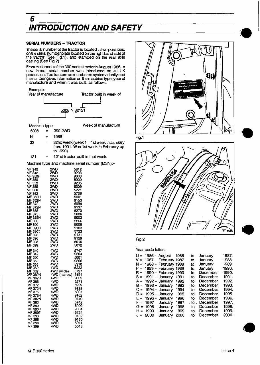
SERIAL NUMBERS - TRACTOR
The serial number of the tractor is located in two posnions.
on the serial number plate located on the right hand side of
the tractor (See Rg.1). and stamped on the rear axle
casting (See Fig.2).
From the launch of the 300 series tractorin August 1986. a
new format serial number was introduced on all UK
production. The tractors are numbered systematically and
the number gives information on the machine type. year of
manufacture and when n was buitt. as follows:
Example:
Vear of manufacture Tractor buitt in week of
I I
'----'1
5008 N 32121
.---__ "T--' LI __ ---,
I
Machine type
Week of manufacture
5008 = 390 2WD
N 1988
32 = 32nd week (week 1 = 1 st week in January
from 1991 . Was 1 st week in February up
to 1990).
121 121 st tractor buitt in that week.
Machine type and machine serial number (MSN):-
MF340 2WO 5812
MF342 2WO 9203
MF350H 2WO 9000
MF350 2WO 5000
MF352 2WO 9205
MF355 2WO 5309
MF360 2WO 5221
MF362 2WO 5726
MF362H 2WD 9001
MF362N 2WO 9153
MF372 2WO 5998
MF372N 2WO 9137
MF365 2WO 5270
MF375 2WO 5006
MF375H 2WO 9003
MF3B3 2WD 5266
MF390 2WO 5008
MF390H 2WO 9163
MF390T 2WO 5723
MF393 2WO 9131
MF396 2WO 9129
MF398 2WO 5010
MF399 2WO 5012
MF340 4WD 5747
MF342 4WD 9204
MF350 4WD 5001
MF352 4WD 9206
MF355 4WD 5310
MF360 4WD 5222
MF362 4WD (wide) 5727
MF362N 4WD (narrow) 9154
MF352H 4WD 9002
MF365 4WD 5271
MF372 4WD 5999
MF372N 4WD 9138
MF375 4WD 5007
MF375H 4WD 9162
MF362N 4WD 9140
MF383 4WD 5742
MF390 4WD 5009
MF390H 4WD 9004
MF390T 4WD 5724
MF393 4WD 9132
MF396 4WD 9130
MF398 4WD 5011
MF399 4WD 5013
M-F 300 series
Fig.2
Vear code letter:
U = 1986 - August 1986
V = 1987 - February 1987
N = 1988 - February 1988
P = 1989 - February 1989
R = 1990 - February 1990
S = 1991 - January 1991
A = 1992 - January 1992
B = 1993 - January 1993
C = 1994 - January 1994
D = 1995 - January 1995
E = 1996 - January 1996
F = 1997 January 1997
G = 1998 January 1998
H = 1999 January 1999
J = 2000 January 2000
'.
ffI
=;f
•
to January 1987.
to January 1988.
to January 1989.
to January 1990.
to December 1990.
to December 1991.
to December 1992.
to December 1993.
to December 1994.
to December 1995.
to December 1996.
. to . December 1997.
to December 1998.
to December 1999.
to December 2000.
•
Issue 4
•
',-- ..
•
7
INTRODUCTION AND SAFETY
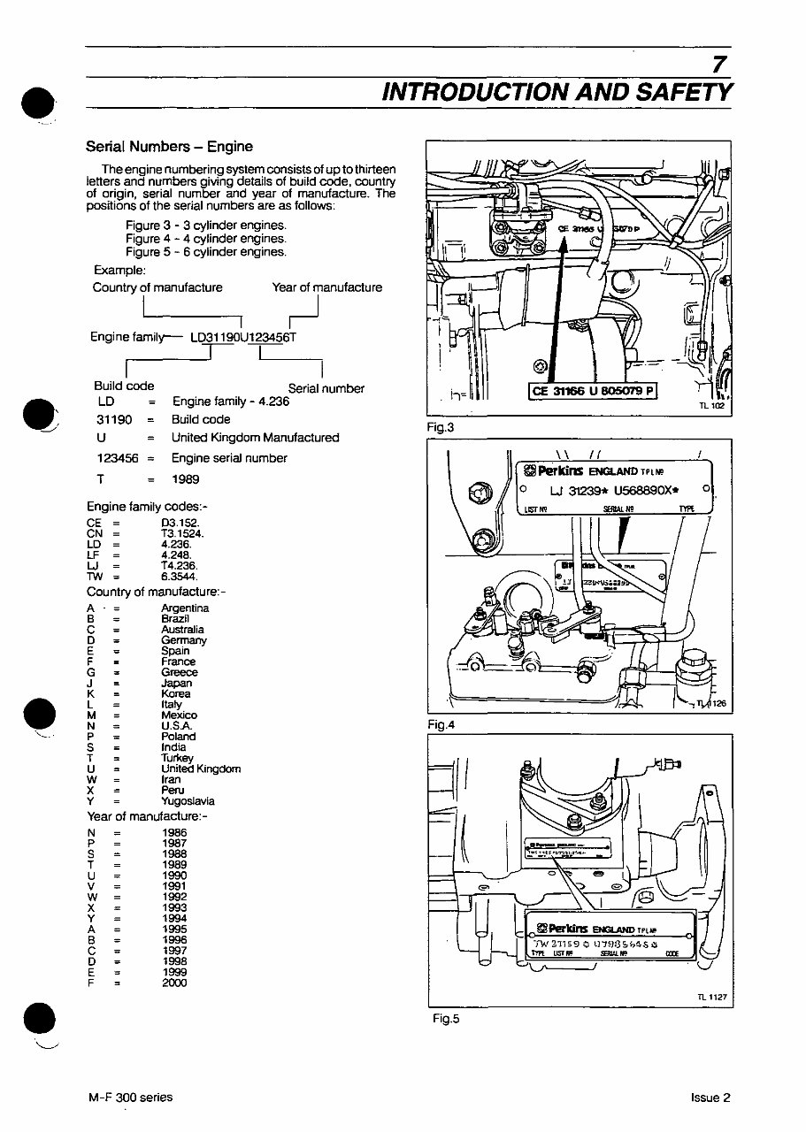
Serial Numbers - Engine
The engine numbering system consists of up to thirteen
letters and numbers giving details of build code, country
of origin, serial number and year of manufacture. The
postlions of the serial numbers are as follows:
Figure 3 - 3 cylinder engines.
Figure 4 - 4 cylinder engines.
Figure 5 - 6 cylinder engines.
Example:
Country of manufacture Year of manufacture
I I
L----_--., I
Engine family-- LD31190UI23456T
Build code
LD
31190
U
Serial number
Engine family - 4.236
Build code
United Kingdom Manufactured
123456 = Engine serial number
T 1989
Engine family codes:-
CE 03.152.
CN T3.1524.
LD 4.236.
LF 4.248.
W T4.236.
TW 6.3544.
Country of manufacture:-
A Argentina
B Brazil
C Australia
o
E Spain
F France
G
J Japan
K Korea
L Italy
M
N U.SA
P Poland
S India
T Tur1<ey
U United Kingdom
W Iran
X Peru
y
Year of manufacture:-
N 1986
P 1967
S 1988
T 1989
U 19!XJ
V 1991
W 1992
X 1993
Y 1994
A 1995
B 1996
C 1997
o 1998
E 1999
F 2000
M-F 300 series
IL-;
II \
'; l
__ I-' 11
@ --
CE 31166 U B05079 P , , ..
TLl02
Fig.3
\\ 1/
gj!Perkins ENGLAND TPUO
o W 31239* U568890X*
o
LJSr"
""'" "
-' [
Fig.4
ENGI.AHD
-rw 2.115 9 0 S f.,4S 1)
T'!'PE USTfIIC !EIIAi."'-' au
TL 1127
Fig.5
Issue 2
You're Reading a Preview
What's Included?
Fast Download Speeds
Online & Offline Access
Access PDF Contents & Bookmarks
Full Search Facility
Print one or all pages of your manual
$39.99
Viewed 10 Times Today


Secure transaction
What's Included?
Fast Download Speeds
Online & Offline Access
Access PDF Contents & Bookmarks
Full Search Facility
Print one or all pages of your manual
$39.99
- Get the comprehensive Massey Ferguson MF365 Tractor Service & Repair Manual for all your troubleshooting and replacement needs.
- Includes step-by-step instructions, clear images, and exploded-view illustrations for easy understanding.
- Essential for both professional mechanics and DIY enthusiasts to maintain and service the tractor.
- Regular maintenance is crucial for the durability of your tractor, and this manual provides the manufacturer's recommended troubleshooting charts and replacement procedures.
- Save on repairs, reduce downtimes, and keep your tractor running smoothly with the help of this manual.
- Convenient digital format allows easy access, search, and bookmarking on various electronic devices.
- Printable for those who prefer a physical copy.
- Language: English
- Compatibility: Works on various electronic devices including PC, Mac, Android, and Apple devices.
- Requirements: Adobe Reader (free)
Please note: This is a comprehensive repair manual that provides all the necessary procedures for servicing and maintaining your tractor.


