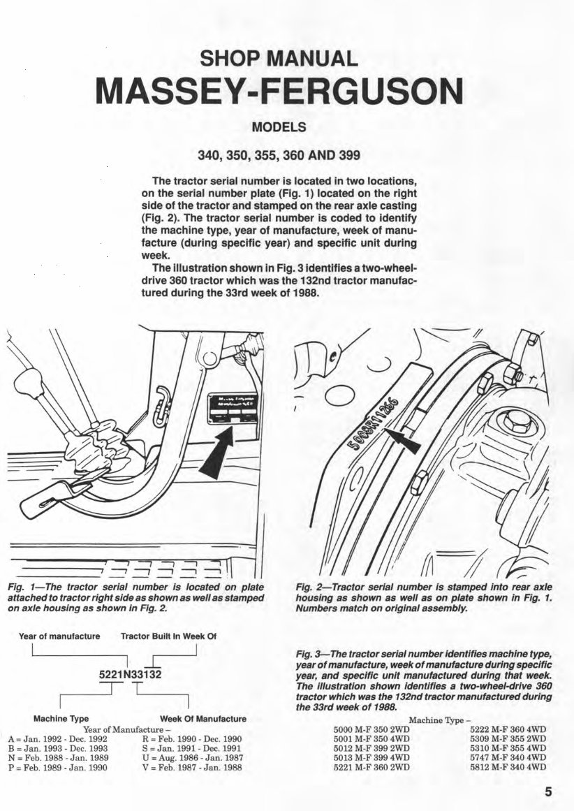
SHOP MANUAL MASSEY-FERGUSON MODELS 340,350,355,360 AND 399 The tractor serial number is located in two locations, on the serial number plate (Fig. 1) located on the right side of the tractor and stamped on the rear axle casting (Fig. 2). The tractor serial number is coded to identify the machine type, year of manufacture, week of manu- facture (during specific year) and specific unit during week. The illustration shown in Fig. 3 identifies a two-wheel- drive 360 tractor which was the 132nd tractor manufac- tured during the 33rd week of 1988. -, -, -. 1 ---, ---, ---, --, ---, ------- -- -- -- -- -- . Fig. 1-The tractor serial number is located on plate attached to tractor right side as shown as well as stamped on axle housing as shown in Fig. 2. Year of manufacture Tractor Built In Week Of I-L 5221N33132 ~ ___ =r-~ T~ __ ~ Machine Type Week Of Manufacture Year of Manufacture - A = Jan . 1992 - Dec. 1992 R = Feb. 1990 - Dec. 1990 B = Jan. 1993 - Dec. 1993 S = Jan. 1991 - Dec. 1991 N = Feb . 1988 - Jan . 1989 U = Aug. 1986 - Jan. 1987 P = Feb. 1989 - Jan. 1990 V = Feb . 1987 - Jan. 1988 Fig. 2-Tractor serial number is stamped into rear axle housing as shown as well as on plate shown in Fig. 1. Numbers match on original assembly. Fig. 3-The tractor serial number identifies machine type, year of manufacture, week of manufacture during specific year, and specific unit manufactured during that week. The illustration shown identifies a two-wheel-drive 360 tractor which was the 132nd tractor manufactured during the 33rd week of 1988. Machine Type - 5000 M-F 350 2WD 5222 M-F 360 4WD 5001 M-F 350 4WD 5309 M-F 355 2WD 5012 M-F 399 2WD 5310 M-F 355 4WD 5013 M-F 399 4WD 5747 M-F 340 4WD 5221 M-F 360 2WD 5812 M-F 340 4WD 5
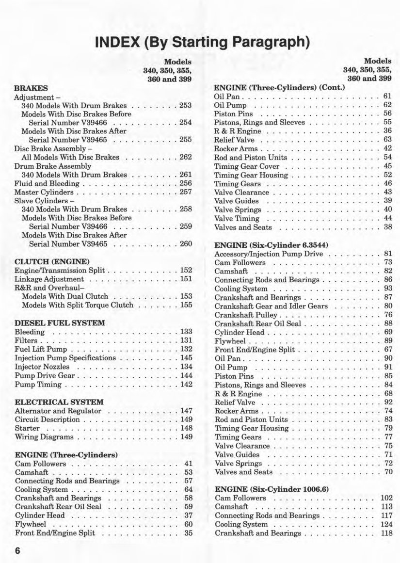
INDEX (By Starting Paragraph) BRAKES Adjustment - 340 Models With Drum Brakes Models With Disc Brakes Before Serial Number V39466 . . . Models With Disc Brakes After Serial Number V39465 . . Disc Brake Assembly - All Models With Disc Brakes Drum Brake Assembly 340 Models With Drum Brakes Fluid and Bleeding . Master Cylinders . . . . . . . . . Slave Cylinders - 340 Models With Drum Brakes Models With Disc Brakes Before Serial Number V39466 . . . . Models With Disc Brakes Mter Serial Number V39465 CLUTCH (ENGINE) EnginefI'ransmission Split . Linkage Adjustment . . . . R&R and Overhaul- Models With Dual Clutch Models With Split Torque Clutch DIESEL FUEL SYSTEM Bleeding .. . Filters ........... . Fuel Lift Pump . . . . . . . Injection Pump Specifications Injector Nozzles Pump Drive Gear. Pump Timing . . . ELECTRICAL SYSTEM Alternator and Regulator Circuit Description . Starter ..... . Wiring Diagrams . . ENGINE (Three-Cylinders) Cam Followers . . . . . . . . . Camshaft ........... . Connecting Rods and Bearings Cooling System . . . . . . Crankshaft and Bearings Crankshaft Rear Oil Seal Cylinder Head . . . . . Flywheel ....... . Front EndlEngine Split 6 Models 340, 350, 355, 360 and 399 .253 .254 .255 .262 .261 .256 .257 .258 .259 .260 . 152 . 151 .153 .155 . 133 .131 . 132 .145 .134 .144 . 142 . 147 .149 .148 .149 41 53 57 64 58 59 37 60 35 Models 340, 350, 355, 360 and 399 ENGINE (Three-Cylinders) (Cont.) Oil Pan. . . 61 Oil Pump ......... 62 Piston Pins ....... . 56 Pistons, Rings and Sleeves 55 R & R Engine 36 Relief Valve . . . . . 63 Rocker Arms . . . . . 42 Rod and Piston Units 54 Timing Gear Cover 45 Timing Gear Housing . 52 Timing Gears 46 Valve Clearance 43 Valve Guides 39 Valve Springs 40 Valve Timing 44 Valves and Seats 38 ENGINE (Six-Cylinder 6.3544) AccessorylInjection Pump Drive Cam Followers ... .. ... . Camshaft ........... . Connecting Rods and Bearings . Cooling System . . . . . . . . . Crankshaft and Bearings .... Crankshaft Gear and Idler Gears Crankshaft Pulley. . . . . . Crankshaft Rear Oil Seal . Cylinder Head. . . . . . Flywheel ........ . Front EndlEngine Split . Oil Pan .. . Oil Pump .. ..... . Piston Pins ...... . Pistons, Rings and Sleeves R & REngine Relief Valve ..... Rocker Arms . . . . . Rod and Piston Units Timing Gear Housing . Timing Gears Valve Clearance Valve . Guides Valve Springs . Valves and Seats ENGINE (Six-Cylinder 1006.6) Cam Followers ........ . Camshaft ........... . Connecting Rods and Bearings . Cooling System . . . . . . Crankshaft and Bearings . . . . 81 73 82 86 93 87 80 76 88 69 89 67 90 91 85 84 68 92 74 83 79 77 75 71 ·72 70 102 113 117 124 118
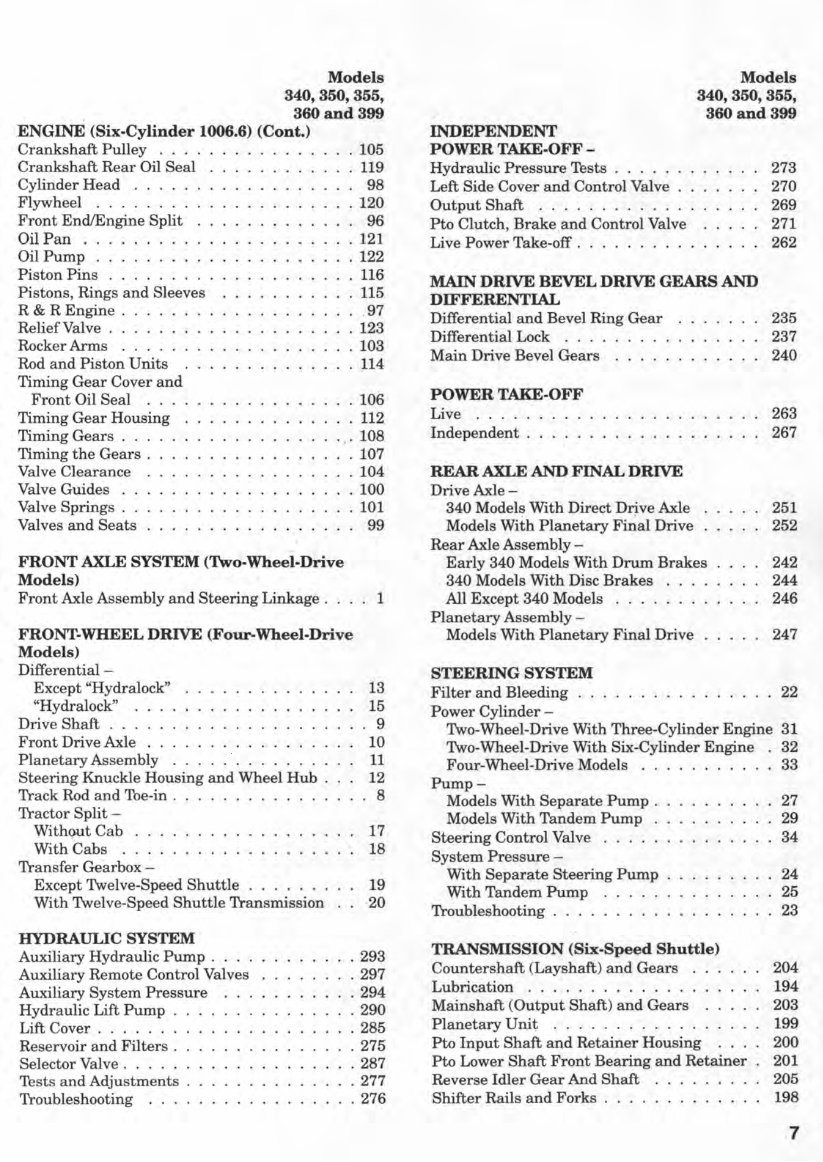
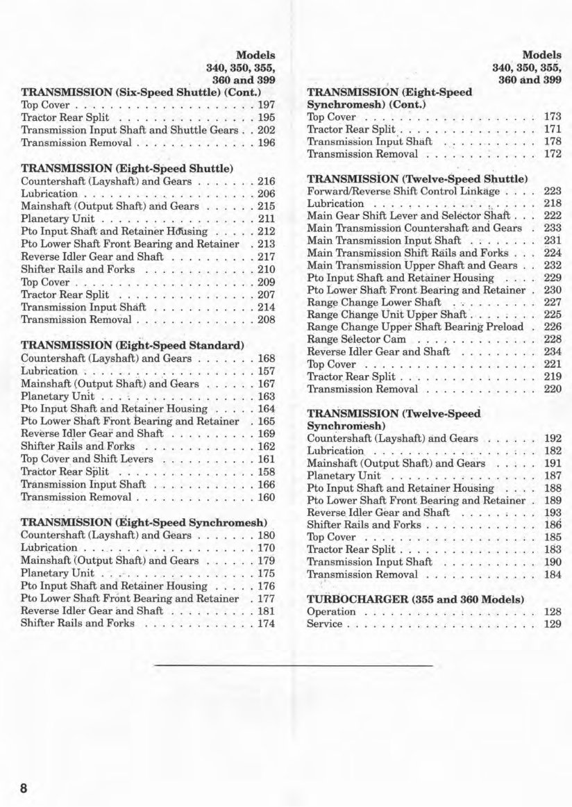
Models 340, 350, 355, . 360 and 399 ENGINE (Six-Cylinder 1006.6) (Cont.) Crankshaft Pulley . . . . Crankshaft Rear Oil Seal Cylinder Head . . . . . Flywheel ....... . Front EndlEngine Split Oil Pan .... . Oil Pump ....... . Piston Pins . . . . . . . Pistons, Rings and Sleeves R& REngine . Relief Valve .... . . Rocker Arms . . . . . Rod and Piston Units Timing Gear Cover and Front Oil Seal ... Timing Gear Housing Timing Gears . . . Timing the Gears . Valve Clearance Valve Guides .. Valve Springs . . Valves and Seats " " FRONT AXLE SYSTEM (Two-Wheel-Drive Models) .105 · 119 · 98 .120 · 96 .121 .122 116 · 115 · .97 .123 .103 · 114 .106 · 112 .108 .107 .104 .100 .101 99 Front Axle Assembly and Steering Linkage. . . . 1 FRONT-WHEEL DRIVE (Four-Wheel-Drive Models) Differential- Except "Hydralock" ~'Hydralock" . Drive Shaft . . . . . Front Drive Axle . . Planetary Assembly Steering Knuckle Housing and Wheel Hub . Track Rod and Toe-in . Tractor Split - WithQut Cab . . . With Cabs .... Transfer Gearbox - Except Twelve-Speed Shuttle With Twelve-Speed Shuttle Transmission HYDRAULIC SYSTEM Auxiliary Hydraulic Pump . Auxiliary Remote Control Valves Auxiliary System Pressure Hydraulic Lift Pump . Lift Cover ...... . Reservoir and Filters . Selector Valve ..... Tests and Adjustments . Troubleshooting .... 13 15 . 9 10 11 12 . 8 17 18 19 ·20 .293 .297 .294 .290 .285 .275 .287 .277 .276 Models 340, 350, 355, 360 and 399 INDEPENDENT POWER TAKE-OFF - Hydraulic Pressure. Tests . Left Side Cover and Control Valve Output Shaft . . . . . . . . . . . Pto Clutch, Brake . and Control Valve Live Power Take-off. . . . . . . . . . MAIN DRIVE BEVEL DRIVE GEARS AND DIFFERENTIAL Differential and Bevel Ring Gear Differential Lock .... Main Drive Bevel Gears POWER TAKE-OFF Live .... . Independent ..... . REAR AXLE AND FINAL DRIVE Drive Axle- 340 Models With Direct Drive Axle . . Models With Planetary Final Drive Rear Axle Assembly - Early 340 Models With Drum Brakes 340 Models With Disc Brakes All Except 340 Models . . . . . . . Planetary Assembly - Models With Planetary Final Drive STEERING SYSTEM 273 270 269 271 262 235 237 240 263 267 251 252 242 244 246 247 Filter and Bleeding . . . . . . . . . . . . . . . . 22 Power Cylinder - Two-Wheel-Drive With Three-Cylinder Engine 31 Two-Wheel-Drive \yith Six-Cylinder Engine 32 Four-Wheel-Drive Models . . 33 Pump- Models With Separate Pump . 27 Models With Tandem Pump 29 Steering Control Valve . . . . . 34 System Pressure - With Separate Steering Pump 24 With Tandem Pump 25 Troubleshooting . . . . . . . . . 23 TRANSMISSION (Six-Speed Shuttle) Countershaft (Layshaft) and Gears . 204 Lubrication . . . . . . . . . . . . . . 194 Mainshaft (Output Shaft) and Gears 203 Planetary Unit ., ......... , .. 199 Pto Input Shaft and Retainer Housing 200 Pto Lower Shaft Front Bearing and Retainer 201 Reverse Idler Gear And Shaft 205 Shifter Rails and Forks . . . . . . . . . . .. 198 7
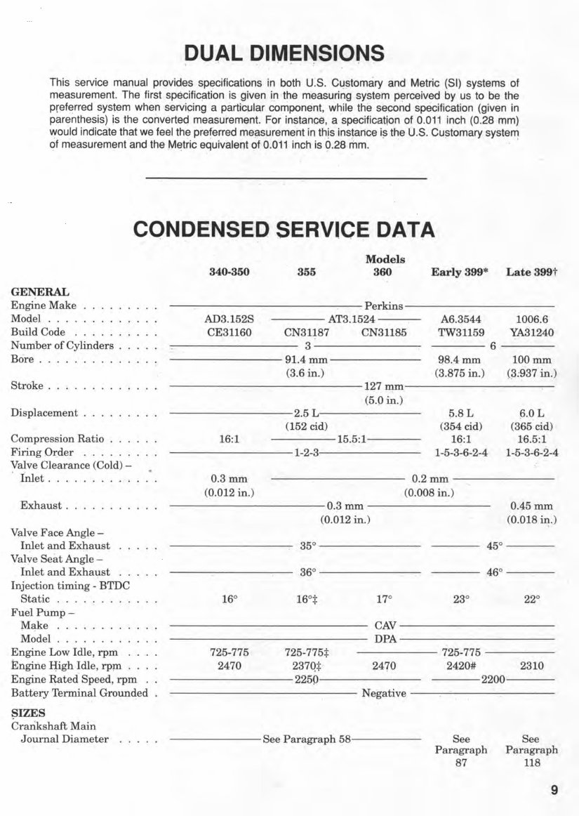
DUAL DIMENSIONS i • ' . w ' , ~ ' • This service manual provides specifications in both U~S. C~?tomary and Metric (SI) systems of measurement. The first specific1=ltion is given in the m'easuring system p~rceived by us to be the pref~rred system when servicing a particul'~r component, while the second specification (given in parenthesis) is the converted measurement. For instance, a specification of 0.011 inch (0.28 mm) would indicate that we feel the preferred measurement in this instance is the U.S. C~stomary system of m'easurement and the Metric equivalent of 0.011 inch is 6.28 mm. . . , . .... CONDENSED SERVICE; DATA GENERAL Ep.gine Make MOQel . ' ... Build Code . Number of Cylinders . Bore .. Stroke. Displacement . Compression Ratio Firing Ot:de~ . . ' . Valve Clearance (Cold)- . Inlet ... Exhaust. Val~e Face Angle- I~let and Exhaust Valve Seat Angle - Inlet and Exhaust Injection timing - BTDC Static . ' . : FuelPump- M~ke .. . Model .. . Engine Low Idle, rpm Engine ~igh · Idle, rpJD Engine ~ated Speed, rpm Battery Terminal Groun~ed SIZES Crankshaft Main Journal Diameter Models 340-350 355 360 Early 399* . Perkins AD3.152S AT3.1524 A6.3544 CE31160 CN31187 CN31185 TW31159 3 6 91.4mm 98.4mm (3.6 in.) (3.875 in.) 127mm (5.0 in.) 2.5 L 0.8 L (152 cid) (354 cid) 16:1 15.5:1 16:1 1-2-3 1-5-3-6-2-4 0.3mm 0.2mm (0.012 in.) (0.008 in.) O.~ mm (0.012 in.) 35° 45° 36° 46° 16° 16°:1: 17° 23° CAV DPA 725-775 725-775:1: 725-775 2470 237Q:I: 2470 2420# 2250 2200 Negative ------- See Par~graph ~8----- See Paragraph 87 Late 399t 1006.6 YA31240 100mm (;3:937 in.) ~.OL (365 cid) 16.5:1 1-5-3-6-2-4 , . 0.45 mm (0.018 i~.) 22° 2310 See Paragraph 118 9
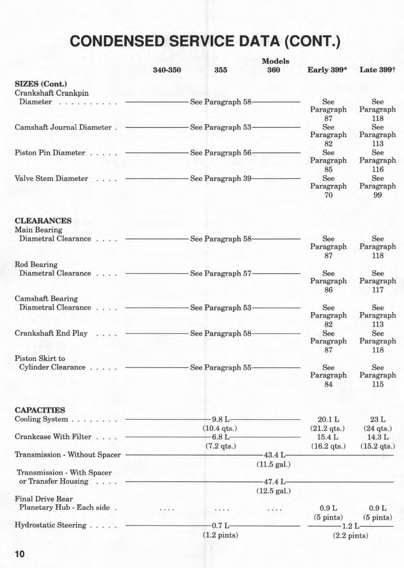
CONDENSED SERVICE DATA (CO NT.) , '. .. , Models 340·350 355 360 Early 399* Late 399t SIZES (Cont.) Crankshaft Crankpin 'Diameter ...... See Paragraph 58 See See Paragraph Paragraph 87 118 Camshaft Journal Diameter . See Paragraph 53 See See Paragraph Paragraph 82 113 Piston Pin Diameter . . . . . See Paragraph 56 See See Paragraph Paragraph 85 116 Valve Stem Diameter .... See Paragraph 39 See See Paragraph Paragraph 70 99 CLEARANCES Main Bearing Diametral Clearance See Paragraph 58 See See Paragraph Paragraph 87 118 Rod Bearing Diametral Clearance See Paragraph 57 See See Paragraph Paragraph 86 117 Camshaft Bearing Diametral Clearance See Paragraph 53 See See Paragraph Paragraph 82 113 Crankshaft End Play See Paragraph 58 See See Paragraph Paragraph 87 118 Piston Skirt to Cylinder Clearance ..... See Paragraph 55 See See Paragraph Paragraph 84 115 CAPACITIES Cooling System . 9.8 L 20.1 L 23 L (10.4 qts.) (21.2 qts.) (24 qts.) Crankcase With Filter 6.8 L 15.4 L 14.3 L . (7.2 qts.) (1?2 qts.) (15.2 qts.) Transmission - Without Spacer 43.4 L (11.5 gal.) Transmission - With Spacer or Transfer Housing 47.4 L (12.5 gal.) Final Drive Rear . Planetary Hub - Each side 0.9 L 0.9 L (5 pints) (5 pints) Hydrostatic Steering . . . . 0.7 L 1.2 L (1.2 pints) (2.2 pints) 10
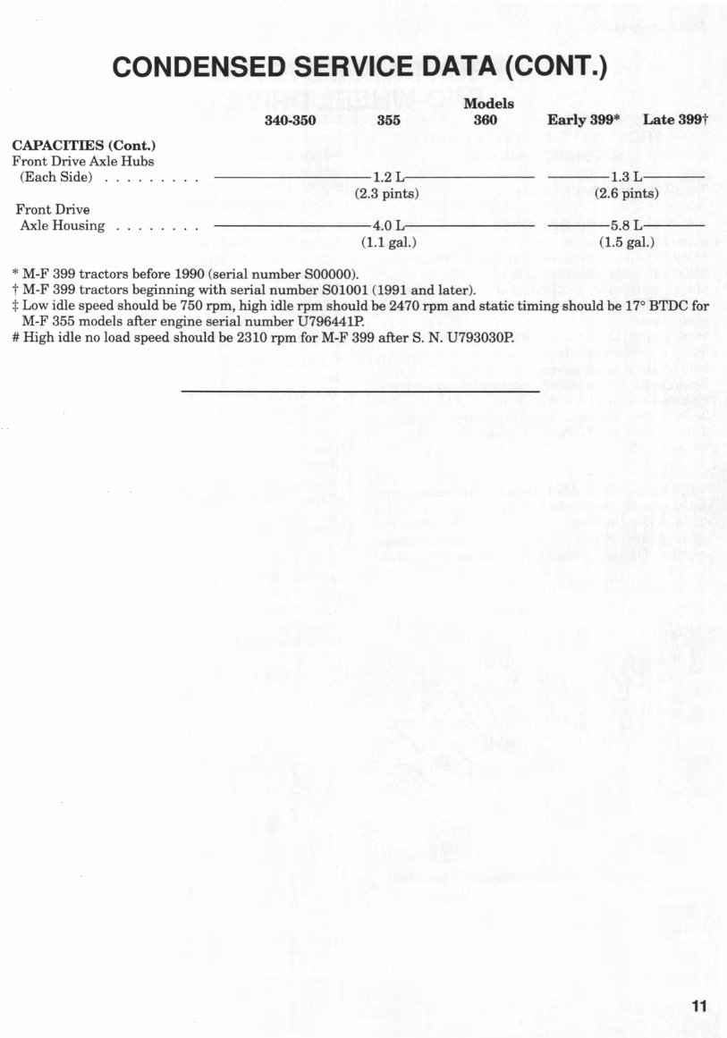
CONDENSED SERVICE DATA (CONT.) CAPACITIES (Cont.) Front Drive Axle Hubs (Each Side) ..... . Front Drive Axle Housing 340·350 355 Models 360 ---------1.2 L-------- (2.3 pints) ---------4.0 L-------- (1.1 gal.) * M-F 399 tractors before 1990 (serial number SOOOOO). t M-F 399 tractors beginning with serial number 801001 (1991 and later). Early 399* Late 399t ----1.3 L---- (2.6 pints) ----5.8 L---- (1.5 gal.) :j: Low idle speed should be 750 rpm, high idle rpm should be 2470 rpm and static timing should be 17° BTDC for M -F 355 models after engine serial number U796441P. # High idle no load speed should be 2310 rpm for M-F 399 after S. N. U793030P. 11
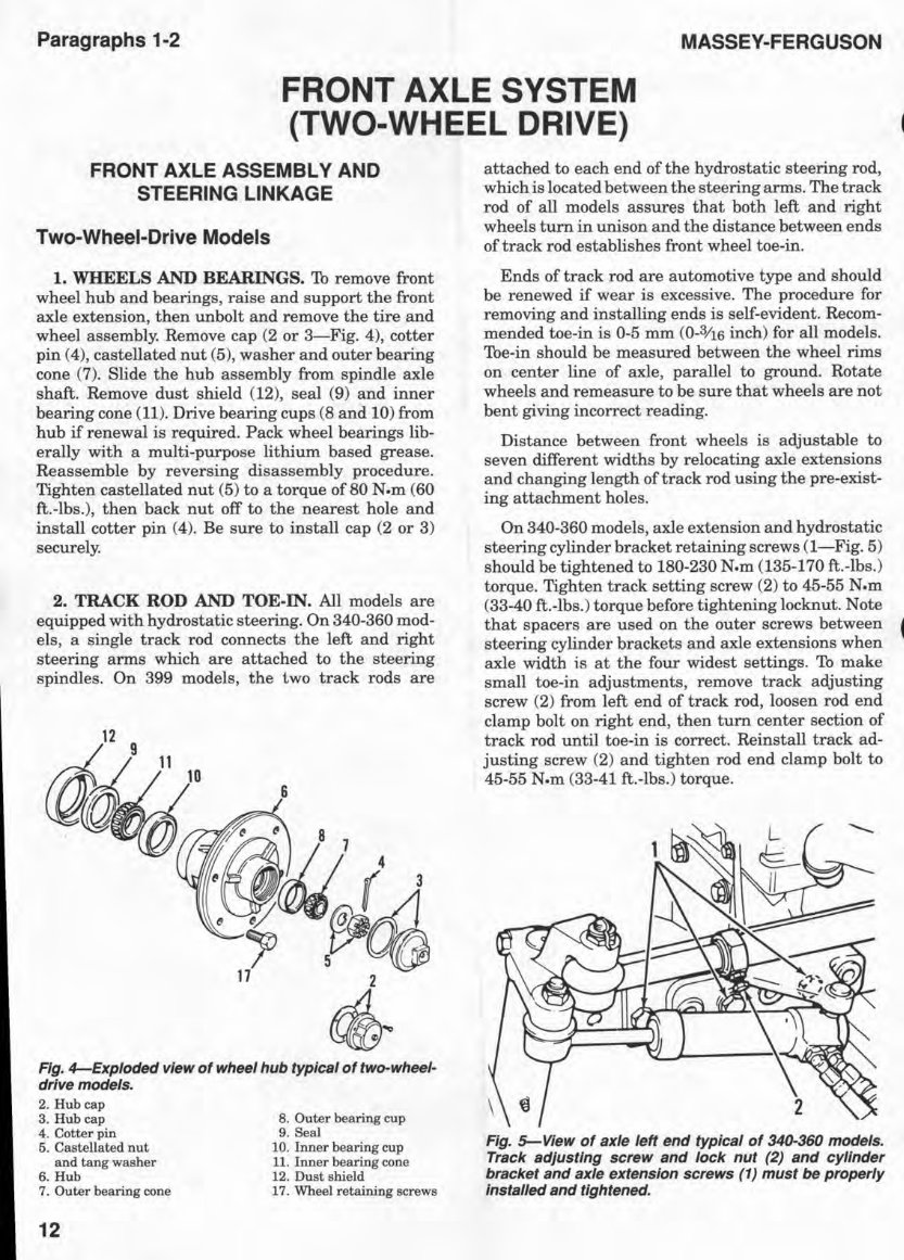
Paragraphs 1-2 MASSEY-FERGUSON FRONT AXLE SYSTEM (TWO-WHEEL DRIVE) FRONT AXLE ASSEMBLY AND STEERING LINKAGE Two-Wheel-Drive Models 1. WHEELS AND BEARINGS. To remove front wheel hub and bearings, raise and support the front axle extension, then unbolt and remove the tire and wheel assembly. Remove cap (2 or 3-Fig. 4), cotter pin (4), castellated nut (5), washer and outer bearing cone (7). Slide the hub assembly from spindle axle shaft. Remove dust shield (12), seal (9) and inner bearing cone (11). Drive bearing cups (8 and 10) from hub if renewal is required. Pack wheel bearings lib- erally with a multi-purpose lithium based grease. Reassemble by reversing disassembly procedure. Tighten castellated nut (5) to a torque of 80 N.m (60 ft.-Ibs.), then back nut off to the nearest hole and install cotter pin (4). Be sure to install cap (2 or 3) securely. 2. TRACK ROD AND TOE-IN. All models are equipped with hydrostatic steering. On 340-360 mod- els, a single track rod connects the left and right steering arms which are attached to the steering spindles. On 399 models, the two track rods are Fig. 4-Exploded view of wheel hub typical of two-wheel- drive models. 2. Hub cap 3. Hub cap 4. Cotter pin 5. Castellated nut and tang washer 6. Hub 7. Outer bearing cone 12 8. Outer bearing cup 9. Seal 10. Inner bearing cup 11. Inner bearing cone 12. Dust shield 17. Wheel retaining screws attached to each end of the hydrostatic steering rod, which is located between the steering arms. The track rod of all models assures that both left and right wheels turn in unison and the distance between ends of track rod establishes front wheel toe-in. Ends of track rod are automotive type and should be renewed if wear is excessive. The procedure for removing and installing ends is self-evident. Recom- mended toe-in is 0-5 mm (0-3;16 inch) for all models. Toe-in should be measured between the wheel rims on center line of axle, parallel to ground. Rotate wheels and remeasure to be sure that wheels are not bent giving incorrect reading. Distance between front wheels is adjustable to seven different widths by relocating axle extensions and changing length of track rod using the pre-exist- ing attachment holes. On 340-360 models, axle extension and hydrostatic steering cylinder bracket retaining screws (I-Fig. 5) should be tightened to 180-230 N.m (135-170 ft.-Ibs.) torque. Tighten track setting screw (2) to 45-55 N.m (33-40 ft.-Ibs.) torque before tightening locknut. Note that spacers are used on the outer screws between steering cylinder brackets and axle extensions when axle width is at the four widest settings. To make small toe-in adjustments, remove track adjusting screw (2) from left end of track rod, loosen rod end clamp bolt on right end, then turn center section of track rod until toe-in is correct. Reinstall track ad- justing screw (2) and tighten rod end clamp bolt to 45-55 N.m (33-41 ft.-Ibs.) torque. Fig. 5-View of axle left end typical of 340-360 models. Track adjusting screw and lock nut (2) and cylinder bracket and axle extension screws (1) must be properly installed and tightened.
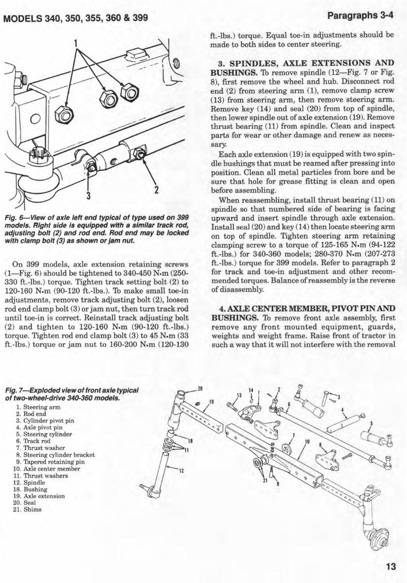
MODELS 340, 350, 355, 360 & 399 Fig. 6-View of axle left end typical of type used on 399 models. Right side is equipped with a similar track rod, adjusting bolt (2) and rod end. Rod end may be locked with clamp bolt (3) as shown or jam nut. On 399 models, axle extension retaining screws (I-Fig. 6) should be tightened to 340-450 N.m (250- 330 ft.-Ibs.) torque. Tighten track setting bolt (2) to 120-160 N.m (90-120 ft.-Ibs.). To make small toe-in adjustments, remove track adjusting bolt (2), loosen rod end clamp bolt (3) or jam nut, then turn track rod until toe-in is correct. Reinstall track adjusting bolt (2) and tighten to 120-160 N.m (90-120 ft.-Ibs.) torque. Tighten rod end clamp bolt (3) to 45 N.m (33 ft.-Ibs.) torque or jam nut to 160-200 N.m (120-130 Fig. 7-Exploded view of front axle typical of two-wheel-drive 340-360 models. 1. Steering arm 2. Rod end 3. Cylinder pivot pin 4. Axle pivot pin 5. Steering cylinder 6. Track rod 7. Thrust washer 8. Steering cylinder bracket 9. Tapered retaining pin 10. Axle center member 11. Thrust washers 12. Spindle 18. Bushing 19. Axle extension 20. Seal 21. Shims ~18 !J- 11 ~ 12 Paragraphs 3-4 ft.-Ibs.) torque. Equal toe-in adjustments should be made to both sides to center steering. 3. SPINDLES, AXLE EXTENSIONS AND BUSHINGS. To remove spindle (12-Fig. 7 or Fig. 8), first remove the wheel and hub. Disconnect rod end (2) from steering arm (1), remove clamp screw (13) from steering arm, then remove steering arm. Remove key (14) and seal (20) from top of spindle, then lower spindle out of axle extension (19). Remove thrust bearing (11) from spindle. Clean and inspect parts for wear or other damage and renew as neces- sary. Each axle extension (19) is equipped with two spin- dle bushings that must be reamed after pressing into position. Clean all metal particles from bore and be sure that hole for grease fitting is clean and open before assembling. When reassembling, install thrust bearing (11) on spindle so that numbered side of bearing is facing upward and insert spindle through axle extension. Install seal (20) and key (14) then locate steering arm on top of spindle. Tighten steering arm retaining clamping screw to a torque of 125-165 N.m (94-122 ft.-Ibs.) for 340-360 models; 280-370 N.m (207-273 ft.-Ibs.) torque for 399 models. Refer to paragraph 2 for track and toe-in adjustment and other recom- mended torques. Balance of reassembly is the reverse of disassembly. 4. AXLE CENTER MEMBER, PIVOT PIN AND BUSHINGS. To remove front axle assembly, first remove any front mounted equipment, guards, weights and weight frame. Raise front of tractor in such a way that it will not interfere with the removal 13
Massey Ferguson MF350 Tractor OEM Service & Repair Manual
This OEM service and repair manual for the Massey Ferguson MF350 tractor provides detailed technical instructions for proper maintenance and repairs. Designed to meet factory specifications, it includes comprehensive repair procedures, troubleshooting techniques, and scheduled maintenance intervals to ensure efficient performance.
The manual covers all major systems, including the engine, transmission, hydraulics, steering, brakes, and electrical components. It also features factory-approved wiring diagrams, torque values, and fluid capacities specific to the MF350 model, making it an invaluable resource for routine servicing and complex mechanical tasks.
Available in a digital format, this manual allows quick access on computers and mobile devices, making it convenient for both workshop and field use. Whether you're a professional mechanic or a hands-on tractor operator, this service and repair manual is essential for keeping your Massey Ferguson MF350 tractor running reliably in demanding agricultural conditions.
Printable: Yes Language: English Compatibility: Pretty much any electronic device, incl. PC & Mac computers, Android and Apple smartphones & tablet, etc. Requirements: Adobe Reader (free)
Recently Viewed
5,521,897Happy Clients
2,594,462eManuals
1,120,453Trusted Sellers
15Years in Business
Price:
Actual Price:
Massey Ferguson MF350 Tractor OEM Service & Repair Manual