

MASSEY FERGUSON MF255 MF265 MF270 MF275 MF290 Shop Manual
What's Included?
Fast Download Speeds
Online & Offline Access
Access PDF Contents & Bookmarks
Full Search Facility
Print one or all pages of your manual


Information and Instructions
This shop manual contains several sections each covering a specific group of
wheel type tractors. The Tab Index on the preceding page can be used to locate
the section pertaining to each group of tractors. Each section contains the
necessary specifications and the brief but terse procedural data needed by a
mechanic when repairing a tractor on which he has had no previous actual
experience.
Within each section, the material is arranged in a systematic order beginning with
an index, which is followed immediately by a Table of Condensed Service
Specifications. These specifications include dimensions, fits, clearances and
timing instructions. Next in order of arrangement is the procedures paragraphs.
In the procedures paragraphs, the order of presentation starts with the front axle
system and steering and proceeding toward the rear axle. The last paragraphs
are devoted to the power take-off and power lift systems. Interspersed where
needed are additional tabular specifications pertaining to wear limits, torqueing,
etc.
HOW TO USE THE INDEX
Suppose you want to know the procedure for R&R (remove and reinstall) of the
engine camshaft. Your first step is to look in the index under the main heading of
ENGINE until you find the entry “Camshaft.” Now read to the right where under
the column covering the tractor you are repairing, you will find a number that
indicates the beginning paragraph pertaining to the camshaft. To locate this
wanted paragraph in the manual, turn the pages until the running index
appearing on the top outside corner of each page contains the number you are
seeking. In this paragraph you will find the information concerning the removal of
the camshaft.
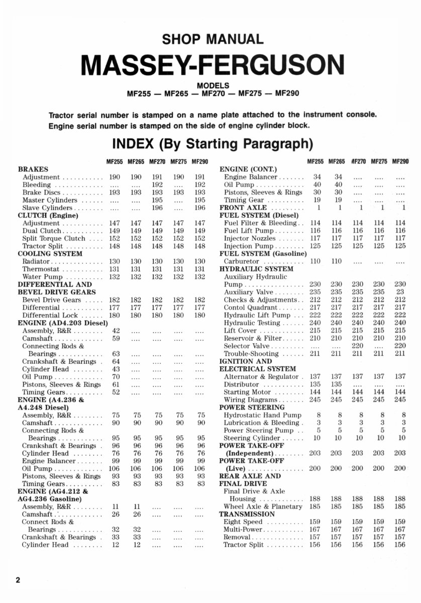
SHOP MANUAL
MASSEY-FERGUSON
MODELS
MF255 - MF265 - MF270 - MF275 - MF290
Tractor serial number Is stamped on a name plate attached to the Instrument console.
Engine serial number Is stamped on the side of engine cylinder block.
INDEX (By Starting Paragraph)
MF255 MF265 MF210 MFZ75 MF290 MF255 MF265 I'IF21O MF275 MF290
BRAKES ENGI~ (CONT.)
Adjustment .. ...... .. . 190 190 191 190 191 Engine Balancer . . . .... 34 34
Bleeding ......... .. .. 192 192 Oil Pump ...... .. .. . .. 40 40
Brake Discs . . . . . . . . . . . 193 193 193 193 193 Pistons, Sleeves & Rings 30 30
Master Cylinders .. ... . 195 195 Timing Gear ........ .. 19 19
Slave Cylinders ........ 196 196 FRONT AXLE ....... .. 1 1 1 1 1
CLUTCH (Engine) FUEL SYSTEM (Diesel)
Adjustment ... ... .. ... 147 147 147 147 147 Fuel Filter & Bleeding . . ll4 ll4 ll4 ll4 ll4
Dual Clutch .. ......... 149 149 149 149 149 Fuel Lift Pump .. ...... ll6 ll6 ll6 ll6 ll6
Split Thrque Clutch .... 152 152 152 152 152 II\i ector Nozzles ....... ll7 ll7 117 ll7 ll7
Tractor Split ... . ...... 148 148 148 148 148 II\iection Pump ... ..... 125 125 125 125 125
COOLING SYSTEM FUEL SYSTEM (Gasoline)
Radiator .............. 130 130 130 130 1 30 Carburetor ........... llO 110
Thermostat ........... 131 131 131 131 131 HYDRAULIC SYSTEM
Water Pump . ......... 132 132 132 1 32 132 Auxiliary Hydraulic
DIFFERENTIAL AND Pump ........ . ....... 230 230 230 230 230
BEVEL DRIVE GEARS Auxiliary Valve ........ 235 235 235 235 23
Bevel Drive Gears ..... 182 182 182 182 182 Checks & Adjustments .. 212 212 212 212 212
Differential ........... 177 177 177 177 177 Contol Quadrant ....... 217 217 217 217 217
Differential Lock .. ... . 1 80 180 180 180 180 Hydraulic Lift Pump ... 222 222 222 222 222
ENGINE (AD4.203 Diesel) Hydraulic 'Jesting .. . ... 240 240 240 240 240
Assembly, R&R ..... . .. 42 Lift Cover ......... ... 215 215 215 215 215
Camshaft ... ... . ...... 59 Reservoir & Filter ...... 210 210 210 210 210
Connecting Rods & Selector Valve ......... 220 220
Bearings ............ 63 Trouble-Shooting ...... 2ll 2ll 2ll 2ll 2ll
Crankshaft & Bearings . 64 IGNITION AND
Cylinder Head ... . .... 43 ELECfRICAL SYSTEM
Oil Pump ............. 70 Alternator & Regulator . 137 137 137 137 137
Pistons, Sleeves & Rings 61 Distributor ........... 135 135
Timing Gears . .. .. .. . .. 52 Starting Motor ........ 144 144 144 144 144
ENGINE (A4.236 & Wiring Diagrams .. ..... 245 245 245 245 245
A4.248 Diesel) POWER STEERING
Assembly, R&R ........ 75 75 75 75 75 Hydrostatic Hand Pump 8 8 8 8 8
Camshaft ............. 90 90 90 90 90 Lubrication & Bleeding . 3 3 3 3 3
Connecting Rods & Power Steering Pump .. 5 5 5 5 5
Bearings .. ........ .. 95 95 95 95 95 Steering Cylinder ...... 10 10 10 10 10
Crankshaft & Bearings . 96 96 96 96 96 POWER TAKE-OFF
Cylinder Head . ... .. .. 76 76 76 76 76 (Independent) .. ...... 203 203 203 203 203
Engine Balancer ... . ... 99 99 99 99 99 POWER TAKE-OFF
Oil Pump ...... . ...... 106 106 106 106 106 (Live) .... . ...... . .. . 200 200 200 200 200
Pistons, Sleeves & Rings 93 93 93 93 93 REAR AXLE AND
Timing Gears .......... 83 83 83 83 83 FINAL DRIVE
ENGINE (AG4.212 & Final Drive & Axle
AG4.236 Gasoline) Housing ............ 188 188 188 188 188
Assembly, R&R .... . ... II 11 Wheel Axle & Planetary 185 185 185 185 185
Cams haft .' .......... .. 26 26 TRANSMISSION
Connect Rods & Eight Speed .......... 159 159 159 159 159
Bearings ...... . ..... 32 32 Multi-Power ........... 167 167 167 167 167
Crankshaft & Bearings . 33 33 Removal .............. 157 157 157 157 157
Cylinder Head . .... .. . 12 12 Tractor Split .......... 156 156 156 156 156
2
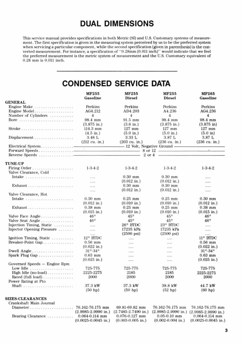
DUAL DIMENSIONS
TIllS service manual provides specifica ti ons in both Metric (81) and U.S. Customary systems of measure-
ment . The first specific ation is given in the measuring system perceived by us LO be the preferred system
when servicing a particular component, while the ~cond specifi cation (given in parenthesis) is the con-
ve rt ed measurement. For instanc~, a specification of ··O.28mm (0. 011 inch )" would indicate that we feel
t.he preferred measurement is the metri c syste m of meas urement and the U.S. Customary e<luivalenL of
0.28 mm is 0.0 11 inch.
CONDENSED SERVICE DATA
GENERAL
Engine Make ....... .
En gine Model. .
Numbe r of Cylind ers
l10re ....
Stroke ....... .
Displacement .......... •..
El cc lr i(: lIi System ....... , ..
Forward Speeds ... .
Reve~ Speeds
TUNE -U P
l- lri ng Order ......... .
Va lve Clearance, Cold
Intake
Exhaust .
Va lve Cleara nce, 1I 0t
Intake ............... .
Exhaust ... ..
Va lve Face Angle . . ..... .
Va lve Seat Angle ......... .
Injection Timi ng, Stat ic
Il\iector Opening Pressu re ..
Ignition Timing, St atic .... .
Breaker-lloinl Gap ........ .
Dwe ll Angle ............. .
Spark Plug Gap . .... .
Governed Speeds - Engine npm
Low Id le ......... .... . .
IIigh Idle (no-load) ....... .
Rated (rull load) ..... .
'lower Rating at Pto
Shaft . . . ........ .. .... .
SIZES-C LEARANCES
Crankshaft M ain Jountal
Diameter ............ .
Hearing Clearance .....
MF265
Gaso li ne
P erki ns
AG4 .212
4
98.4 mm
(3.875 in.)
114 .3 mm
(4 .5 in .)
3.48 L
(2 12 cu. in.)
1-3- 4 -2
0.30 mm
(0 .012 in .)
0.38 mm
(0 .0 15 in .)
46°
46°
.. ,.
12° BTDC
0.56 mm
(0.022 in .)
31 °· 34 °
0.63 mm
(0.025 in.)
725-775
2225·2275
2000
37 .3 kW
(50 hpl
76.162-76. 175 mm
(2 .9985·2.9990 in.)
0.064·0. 114 mm
(0.0025-0.0045 in.)
MF265 MF255
Diese l Diese l
Perkins P erki ns
, \D4 .203 M .236
4 4
9 1. 5 mm 98.4 mm
(3.6 in.) (3.875 in.)
127 mm 127 mm
(5.0 in .) (5.0 in.)
3. 33 L 3.87 L
(203 cu. in .) (236 cu. in .)
12 Volt . Negat ive Grou nd
8 or 12
2 or 4
1-3-4 -2
0.30 mm
(0.0 12 in .)
0.30 mm
(0.012 in.)
0.25 mm
(0.010 in.)
0.25 mm
(0.010 in.)
46'
45 '
26° BTOC
17235 kPa
(2500 psi)
725-775
21 85
2000
37.3 kW
(50 hll)
69.81-69.82 mm
(2.7485·2.7490 in .)
0.076-0.127 mm
(0.003-0.005 in.)
1 -3 -4-2
0.30 mill
(0.012 in.)
0.30 mm
(0.012 in .)
0.25 mm
(0.010 in.)
0.25 mm
(0.010 in.)
45°
45'
23° ErrDC
17235 kPa
(2500 psi)
725-775
21 85
2000
38 .8 kW
(52 hll)
76.162-76.175 mm
(2.9985-2.9990 in.)
0.05-0.10 mm
(0.002-0.004 in.)
MF26,
Gasoline
Pe rkins
AG4.236
4
98.4 mm
(3.875 in)
127 mm
(5.0 In)
3.87 L
(236 cu. in .)
1-3-4-2
0. 30 mm
(0.012 in.)
0.38 mm
(0.015 in.)
46 '
46'
1l
0
1JI1X;
0.56 mm
(0.022 In.)
31°_34°
0.63 mm
(0.025 in.)
726-776
2225-2276
2000
44 .7 kW
(60 hp j
76.162-76. 175 mm
(2.0985-2.9990 in .)
O.064-0. 114 mm
(0.0025-0.0045 in.)
3
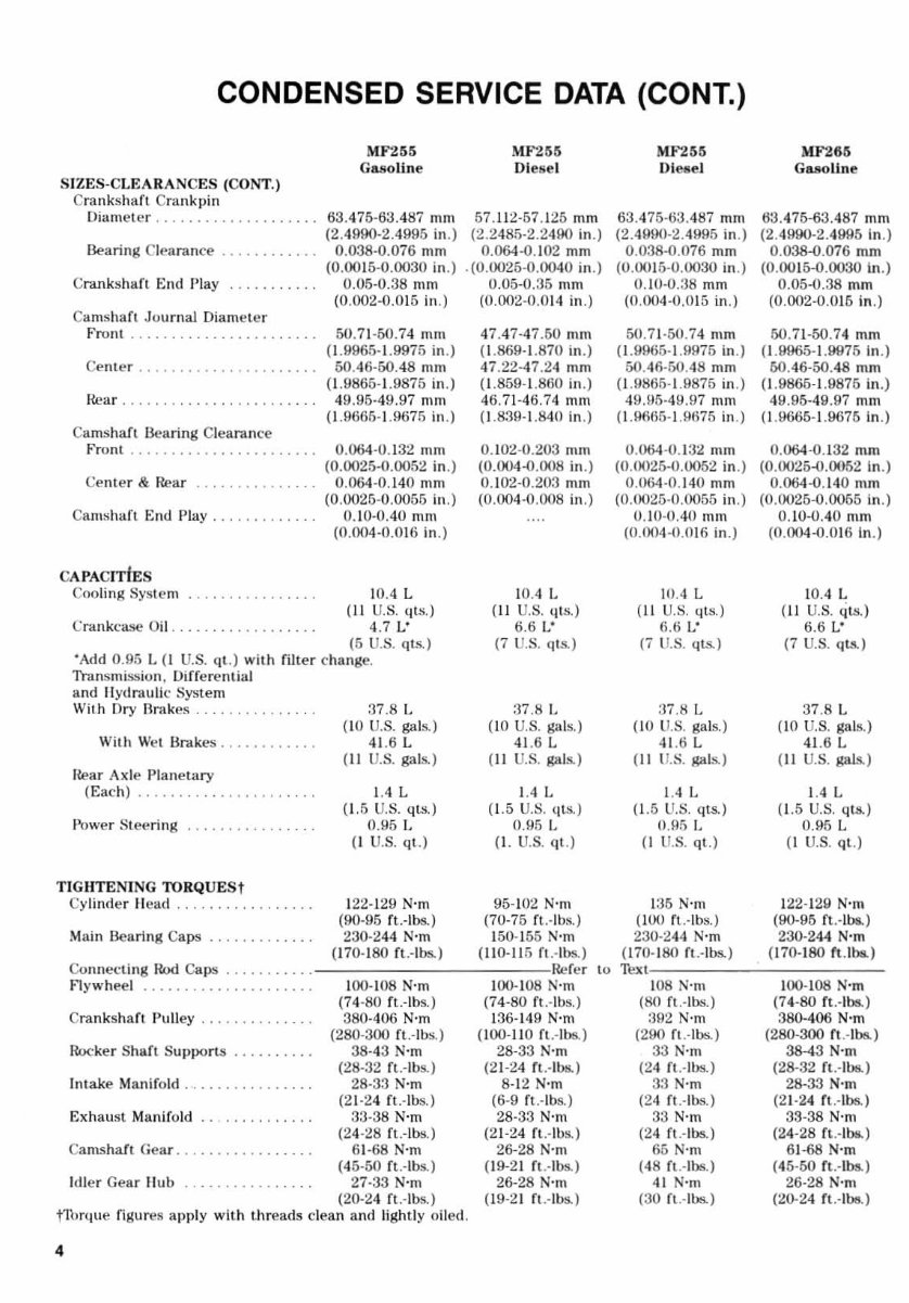
CONDENSED SERVICE DATA (CONT.)
MF255 MF'l55
MF2.'
GasoUne Di ese l Dl etlel
SIZES-CLEARANCES (CONT.)
Crank s hafl Crank pi n
Diameter ... .......... 63.475-63.487 mill 57. 112 -57.125 mm 63.475 -63.487 mm
(2.4990-2.4995 in .) (2.2485-2.2490 in.) (2.4900-2 . 4995 in .)
Bearing Cl earance ....... ... 0.038-0.076 mm 0.064 -0 .102 mm 0.038-0.076 mm
(0.0015-0.0030 in .) .(0.0025-0.0040 in.) (0. 001 5-0.0030 in .)
C nmkshaft End Play 0.05-0.38 mill
(0.002-0.015 in.)
Ca ms haft Journal Diameter
Front .... 50 .71 -50.74 mm
(I .9965-1.9975 in .)
Center .. 50.46-50.48 mm
( 1. 9865- 1. 9875 ill .)
H ea r . . . ............... 49 .95·49,97 mm
( 1. 9665-1.9675 in .)
Camshaft Bearing C1 (!ard. n ce
Front ......... ........... 0.064-0. 132 mill
(0.0025-0.0052 in .)
Ce nl er & Rear ........... 0.064-0.140 mOl
(0,0025-0,0055 in.)
Camshaft End Play 0. 1O-0 AO m ill
(0.004-0.016 ill .)
CA PACITiES
Cooling System lOA L
(II U.S. qts ,)
Cr"mkcase Oil .. . 4.7 L'
(5 U.S. qls. )
'Add 0 .95 L {I U.S. (11.) with riller c hange.
Transmission, Differentilll
and lI ydraulic System
With Dry Rrakes ...... .
With Wei Br-.:tkes .. , .. ... .
Hear Axle Plane t ary
(Eac h) .... . ..... . ...... .. .
Power Steering ....
:)7 .8 L
(10 U.S. gals.)
41.6 L
(II U.S. gals. )
IA L
(1.5 U.S. qts.)
0.95 L
(J U.S. ql .)
TIGHTENING TO RQUESt
Cy linder Head, ..... . . .
Main Bearing Caps . , ....
Connect ing Hod Ca ps .. .
flywhe el ................ _ .. .
Crankshaft Pulley , .
Rocker Shllft Su pports .....
In take Manifold ..
Exhaust Manifold
Ca mshafl Gear ....
hile r Gear Hub
122- 12 9 N·m
(90-95 ft.-Ibs.)
230-2 44 N·m
(l70-ISO ft.-lbs.)
100-108 N-m
(74-80 ft.-Ibs.)
380-406 N·m
(2SO-3OO ft.-Ibs.)
38-43 N-m
(2S-32 ft.-IllS.)
28 - 33 N·m
(2 1-24 fl.-Ills.)
33-38 N·m
(24- 28 ft.-Ibs.)
61-68 N'm
(45- 50 ft .- Ibs.)
27-33 N·m
(20-24 fl.-Its.)
f1brque figures apply with Ulreads clean and light ly oiled.
4
0.05-0. 35 mm
(0.002-0. 014 in .)
47.47-47.60 mill
( 1. 869-1.870 in.)
47 .22-47.24 mm
( 1. 859- 1. 860 in . )
46.71 -46 .74 mm
(1 .839-1.840 in .)
0.102-0.203 mm
(0.004-0.008 in.)
0. 10·.2-0 .203 mill
(0. OO4 -0.008 in.)
lOA L
(J I U.S . qLS. )
6.6 I:
(7 U.S. (lIS.)
:]7.8 ].
(10 U.S. gals.)
41 .6 L
(II U.S. gal s..)
1.4 L
( 1. 5 U.S. ti ts.,
0.95 L
(J. U.S. (II. )
95-102 N·m
(70-75 ft .- Ibs.)
150- 155 N·m
(l1O-1l 5 fl.-I bs.)
Refer
lOO- IOS N·m
(74-80 fl.-Ibs.)
136-149 N·m
(100-110 fl. -Ibs. )
2S-33 N·m
(21-24 rt .- Ibs..)
8-12 N·m
(6-9 rl.-Ibs.)
2S-33 N'm
(21-24 ft.-lbs.)
26-28 N'm
(19-2 1 f t. -Ibs.)
26-28 N· m
(19-2 1 ft. -Ibs.)
0. 10-0.38 mm
(0.004-0.015 in.)
50.71·50.74 mm
( 1. 9965-1.1)975 In .)
5OA6-50 .48 mm
(1.9865· 1. 9875 in.)
49JJ5 - 49 .97 mm
(1.9605- 1. 9675 in.)
0. 064 -0. 132 mm
(0.0025-0.0052 in .)
0.064-0.140 mm
(0.0025-0.0055 in.)
O. lO-OAO mm
(0.004-0.0 16 in .)
iliA L
(II U.S. qLS.)
6.6 L'
(7 U.S. qts. )
: 17 .8 L
( 10 U.S. gals.)
41.6 L
(II I1.S. gal s..)
1.4 L
(1.5 U.S, (Its.)
0. 95 I.
(l U.S. ql .)
135 N·m
(lOU rl.·lbs.)
230-24'1 N·m
(170-180 fl. -Ibs. )
to Text
lOS N'm
(SO fl. -Ibs. )
392 N·m
(290 fl.-Ibs.)
33 N·m
(24 ft .· lbs. )
33 N- m
(24 fl.-Ibs.)
33 N·m
(2 4 ft .- Ibs. )
65 N· m
(48 ft.-Ills.)
41 N·m
(30 fl .- Ibs. )
MF26.
Gasoline
63.475-63.487 mm
(2.4990-2.4995 in .)
0.038-0.076 mm
(0.0015-0.0030 in.)
0.05-0.38 rnm
(0.002-0.015 in .)
50. 71 -50. 74 mm
(1.9965-1.9976 In.)
6O A6-50.48 mm
(1.9865-1.9876 Ill .)
411 .95-49.97 mm
(1.9665-1.9675 In.)
0.064-0.132 mm
(0.0025-0.0052 In.)
0.064-0. 14 0 mm
(0.0025-0.0056 in .)
0 .10-0040 mm
(0.004-0.016 in .)
lOA L
( ll U.S. qts.)
6.6 L'
(7 U.S. qtA)
37.8 L
(10 U.S. gals.)
41.6 L
(J I U.S. gals.)
1.4 L
(1.5 U.S. qts.)
0.95 L
(I U.S. ql .)
122- 1 29 N·m
(90-95 ft.-Ibs.)
230-244 N·m
(l70-ISO ft.JbIl.)
100- lOS N·m
(74-80 (t .- Ibs.)
381HOO N·m
(280-300 ft .- I bs..)
38-43 N-m
(28-32 rt.-Ilwl)
28-33 N'm
(2 1-2 4 ft ,- Ibs.)
33-38 N·m
(24-28 (t .- II>8. )
61-68 N-m
(45-60 rt .- Ibs.)
26-28 N·nl
(:l0-24 (t .- lbe.)
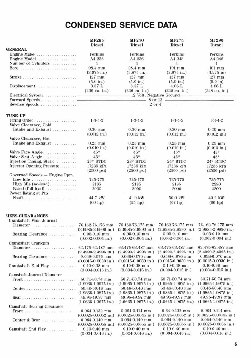
CONDENSED SERVICE DATA
G ENE R AL
Engine Make .............. • • ..
Engine Model .. . ........ .
Number of Cy lind ers ....... .
Bore . .... .. ..... .
Stroke ..
Disp l acement .. .... .......... .
MF265
Olese l
Perkins
A4 .236
4
98 .4 mm
(3.875 in .)
127 mm
(5.0 in.)
3.87 L
(236 Cll . in.)
MF270
Diese l
Pe rkins
A4 .236
4
MF275
Diese l
Perki ns
A4 .248
4
98 .4 mm IOJ mm
(3.875 in.) (3.975 in .)
127 mm 127 mill
(5.0 in .) (5.0 in.)
3.87 L 4.06 L
(236 cu. in.) (248 cu. in.)
MF290
Diesel
Perki ns
A4 .248
4
IOlmm
(3.975 in )
127 mm
(5.0 in)
4.06 L
(248 cu. in .)
E I e<: lric a1 System ...... ..... .. .. ===========~ ' 2~V~ol~t , NegatiVe;~ro~un~d~==========
Fo rwa rd Speed s. . . . . . . •• . . . . . 8 or 12
Reverse S) >eeds . . . . . . . . . . 2 or 4
T UNE·UP
Firing Order . ......... . .. •..
Va lve Clearance, Co ld
Intake and Exhaust ....
Val ve Clearance, Hot
Intake and Exhaust .. .. .. . . . . .
Va lve Face Angle . ...... .
Va lve Sea t Angle. . . . . . ... .
bijection Timing, Stat ic ........ .
lrijector Opening Pressure .... .
Governed Speeds - Engine Hpm.
Low Idl e. . ... . . . . . .. .
High I dle (no-load) ..
Rated (fu ll load) . .. . ..... . . . .
Power Rating at Pto
Shart . . . . . . . . . . . . . .. . . .. . . .
~IZES-CLEARANCES
Crankshart Main Journal
Diameter.
Bearing Clearance
Cranks hart Crankpin
Diamete r. . . ........ .
Bearing Clearance
Crankshart End Play
Cams hart Journal Diam e te r
Front ....... ... ............ .
Center .
Rear . .
Camshart Bearing Cle arance
Front
Ce nt er & Rear
Cams haft End Play ...... . . .
1-3-'1-2
0. 30 mm
(0.012 in.)
0.25 mm
(0.0 10 in .)
45°
45
0
23° IJrDC
17235 kPa
(2500 I >si)
725-775
2 185
2000
44.7 kW
(60 hpj
76. 162·76.175 mm
(2.9985·2.9990 in.)
0.05-0. 10 mm
(0.002·0.004 in .)
63.475·63.487 mm
(2 .4990·2.4995 in.)
0.038-0.076 mm
(0.0015·0.0030 in .)
0.10-0.38 mm
(0.004-0.015 in.)
50.71 ·50.74 mm
(1.9965- 1. 9975 in.)
50.46-50.48 mm
(1.9865- 1. 9875 in .)
49.95-49.97 mm
(1.9665- 1. 9675 in.)
0.064-0. 132 mm
(0.0025.0.0052 in .)
0.064-0. 14 0 mm
(0.0025·0.0055 in.)
0. 10·0.40 mm
(0.004-0.016 in .)
1-3·4-2
0.30 mm
(0. 0I2 in .)
0.25 mm
(0.010 In .)
45°
23 ° BTDC
17 235 kPa
(2500 psi)
725-775
2 185
2000
41 .0 kW
(55 hll)
76.162 -76. 17 5 mm
(2.0085-2.9990 in.)
0.05·0. 10 mm
(0.002.0.004 in .)
63.475·63.487 mm
(2.4900-2.4995 in.)
0.038 ·0 .076 mm
(0 .0015·0.0030 in.)
0.10-0.38 mm
(0.004·0.015 in.)
50.71-50.74 mm
(1.9965· 1. 9975 in .)
50.46-50.48 mm
(1.9865- 1. 9875 in .)
49.05-49.97 mm
(1.0fi65- J.9675 in .)
0.064·0. 114 mm
(0.0025-0.0045 in.)
0.064-0.140 mm
(0.0025-0.0055 in.)
0.10-0.40 mm
(0.004-0.0 16 in .)
1-3-4-2
0.30 mm
(0.012 in.)
0 .25 mm
(0 .010 in.)
45°
45
0
24 ° IJroc
17235 kPa
(2500 I>si)
725-775
2 185
2000
50.0 kW
(67 hi»
76. 162-76. 17 5 mm
(2.9985-2.9990 in .)
0.05-0. 10 mm
(0.002-0.004 in.)
63.475-63.487 mm
(2.4990-2.4995 in.)
0.038-0.076 mill
(0.001 5-0.0030 in .)
0.10-0.:38 mm
(0.004-0.015 in.)
50. 71 -50.74 mm
( 1. 9965- 1. 9975 in .)
50.46-50.48 mm
(1.9865-1.9875 in .)
49.95-49.97 mm
(}'9665-1.9675 in .)
0.64-0.132 mm
(0.0025-0.0052 in .)
0.064-0. 14 0 mm
(0.0025-0.0055 in.)
0. 10-0.40 mm
(0.004-0.016 in .)
1 -3- 4-2
0.30 mm
(0.012 in .)
0.25 mm
(0.010 in .)
<&0
45
0
24° BTDC
17235 kP'd.
(2500 psI)
725-775
2380
2200
49.2 kW
(66 hpj
76 . 162- 76.175 mOl
(2 .9985-2.9990 in .)
0.05-0. 10 mOl
(O.0()2.o.004 in.)
63.475-63.487 mm
(2 .4990·2 .4 995 in.)
0.038-0.076 mm
(0.0015-0.0030 in .)
0.10-0.38 mm
(0.004-0 .015 in .)
50.71-50.74 mm
(1.9960-1.9975 In .)
50.46-50.48 mm
(1.9865-1.9875 in .)
49.95-49.97 mm
( 1. 9665- 1. 9675 in .)
0.064-0. 114 mm
(O.0025-lXUX)45 in .)
0 .064 -0 .140 mOl
(0.0025-0.0055 in.)
0. 10-0040 mm
(0.004-0.016 in .)
5
Paragraphs '-2 MASSEY - FERGUSON
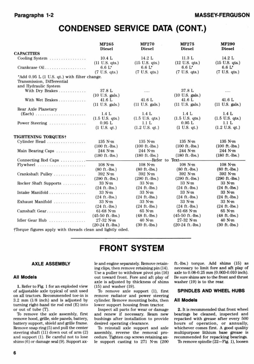
CONDENSED SERVICE DATA (CONT_)
~IF265 MF270
Diese l Di eIJe l
CAPACITIES
Cooling System . . . . . . . . . . . . . . . . lOA L 14.2 L
( 11 U.S. qts.) (I6 U.S. qts.)
Crankc ase Oil .. ........ ..... ... 6 .6 L" 6.6 L"
(7 U. S. qts.) (7 U.S. qts.)
·Add 0.96 L (1 U.S. qt.) with filler change.
Tnmsmission, Differential
and HydrauliC System
With Dry Brakes ............ 37 .8 L
(10 U.S. _)
With W et Brakes .. ........ . 41.6 L 41.6 L
(11 U.S. gals.) (I I U.S. gals.)
near Ax le Planetary
(Each) .... . .. ... . ..... ...... 1.4 L 1.4 L
(1.5 U.S. qts.) (1.5 U.S. qts.)
Power Sleering ........ 0.95 L LlL
(I U.S. qt.) (1.2 U.S. qt.)
TIGHTENING roRQUES t
Cylinder Head ................. 135 N'm 1 35 N'm
(100 rt .-Ibs.) (100 rt .- Ibs.)
Main Bearing Caps ... ..... 244 N'm 244 N-m
(180 rt .- Ibs.) (180 ft .-Ibs. )
Co nnecting Rod Caps .. . Refer lO
Flywheel 108 N-m 108 N'm
(80 ft..-Ibs.) (80 ft.-Ihs.)
Crankshaft Pulley . .. 392 N'm 392 N'm
(290 ft.-Ibs.) (290 ft .- Ibs.)
Rocker Shaft Supports .. 33 N-m 33 N'm
(24 ft .- Ibs. ) (24 ft.-Ibs.)
Intake Manifold ..... 33 N'm 33 N'm
(24 ft.-lbs.) (24 rt .- Ibs.)
Exhaust Manifold .. .......... .. 33 N'm 33 N'm
(24 ft.-lbs. ) (24 rt .- Ibs.)
Camsh art Gear .. 61 -68 N'm 55 N'm
(45-50 ft.-Ibs.) (48 fl .-lbs.)
Id ler Gear Hub 27-32 N'm 40 N'm
(20-24 ft .-l bs.) (30 ft.-Ibs.)
f!b rque figures apply with th reads clea n and lightly o il ed .
AXLE ASSEMBLY
All Model,
1. Refer to Fig. I for an exploded view
of adjus table axle typical of unit used
on all tractors. Recommended toe -in Is
3.2 mm (l /8 inch) and Is adjusted by
tu rning right- hand tie rod end (El into
or out of tube (n .
Th remove the axle assemb ly, first
remove hood , grille, side panels, battery,
battery support, shield and grille frame.
Remove s nap ring (6) and pull the center
s teering s haft (Il) down ou t of arm (2)
and s upport (I) . Be care ful not to lose
shims (6) or damage seal (9). Su pport ax-
6
FRONT SYSTEM
Ie and engine separately. Remove retain-
Ing cli ps, then remove retaining pin (14).
Use a puller to wit hdraw pivot pin (I6)
o ut toward front. Fore and aft play of
axle is adjusted by th ic kness of shims
(15) and was h er (19).
1b remove axle support (1), fi rst
remove radiat or and power stee ring
cy linder . Remove mounting bolts. the n
lower support housing from tractor.
Inspect all parts for wear or damage
and renew if necessary. Ream new
bushings after installati on to provide
des ired operati ng clearance.
1b reinstall axle s upport and axle
asse mbl y, reverse the removal pro-
cedure. Tighten cap screws retaining ax-
le support casti ng to 271 N- m (200
MF276 MF290
Di ese l Di esel
11 .3 L 14.2 L
(12 U.S. q18.) (16 U.S. q18.)
6.6 L· 6.6 L·
(7 U.S. qt.s.) (7 U.S. qts.)
37 .8 L
(10 U.S._)
41.6 L 41.6 L
(11 U.S. gals.) (II U.S._)
1.4 L 1.4 L
(1.5 U.S. ql8.) (l.f) U.S. qts.)
0.95 L LlL
(1 U. S. qt.) (1 .2 U.S. qt .)
135 N'm 1 36 N'm
(100 ft.-Ibs.) ( 100 tt .- Ibs.)
244 N'm 244 N-m
(180 ft .- Ibs.) (180 rt .-Ibs.. )
'!>xl
108 N-m lOS N'm
(SO ft.-lbs.) (80 ft.-Ibs..)
392 N'm 392 N'm
(290 ft.-Ibs.) (290 rt .-lbs.)
33 N'm 33 N'm
(24 ft.-Ibs.) (24 fl .·lbo.)
33 N-m 33N ...
(24 rt.-lbs.) (24 Ct.-Ibs.)
33 N'm 33 N'm
(24 ft.-Ibs.) (24 ft. -Ibs.)
6 1-68 N'm 66 N'm
(45-50 fl. -Ibs.) (48 n .- Ibs.)
27-32 N'm 40 N'm
(20-24 fl.-Ibs.) (30 fl.·ll>o.)
ft .- lbs.) to rque. Add shims (16) as
necessary to limit f ore and aft play of
axle to 0.08-0.26 mm (0.003-0.010 inch).
Be sure shims are to the front and thrust.
was h er (19) ill to t he rear.
SPINDLES AND WHEEL HUBS
All Model.
2. It is recommended that front wheel
bearings be clea ned , inspected and
repac ked with grease arter every 600
hours of ope rati on, or annually,
wh icheve r comes first. A good quality
multipurpose llthlum base grease is
recommended ror repacking bearings.
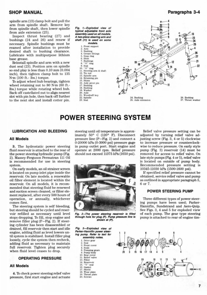
1b remove spindle (22-F'\g. .1) , loosen
SHOP MANUAL
spindle arm (13) clamp bolt and pull the
ann from spindle shaft. I re-move key
from spindle sh aft , then lower spindle
from axle extension (25).
Inspect t hru st bearing (27) and
bushings (24 and 26) and renew if
necessary. Spindle bushings must be
reamed after installation to provide
desired shaft to bushing clearance.
Lubricate with multipurpose lithium
base grease.
Reinstall spindle and arm w it h a new
dust sea l (23). Position ar m on s pindle
so end play is Jess than 0. 10 mm (0.004
inch) , then lighten clamp bolt to 135
N'm (100 f t. - \bs. ) torque.
1b adjust wheel hub bearings, tight en
wh eel retaining nut to 80 N- m (60 f t. -
Jbs.) torque while rotating wh ee l hub.
Back off castellated nul to align nearest
slot with pin hole, then back off furth er
to the next sl ot and install cotte r pin.
Fig. I_Exp /od" vl.w of
typic.' Idju. ttlbl. Iron' .xt.
_mbIy lINd 0If .U mocHI ..
A ~.r..rlng_and
wf'l (H) I. uud on .am.
..... ,.
I. fmnt ... ppon
2. Arm
' .........
4. a"'MefitUnp
t. . Snap ring
II. SIIl m
7 n ... hlnp
8. "0" ring
... "
10. "0 " nn,
II Steomng ...... " "".'1
12 n.. rod
'3. Spindle.,...
14. ~pln
It.. ShImI
18 Ad!: pi vot pin
L 7 llIah.I"lI
18 . Hulhl ng
Ig. Wuher
2<1. A" I/:
21 Wood ruff k~
U . Spindle
" .. "
Paragraphs 3·4
POWER STEERING SYSTEM
WBRICATION AND BLEEDING
All Models
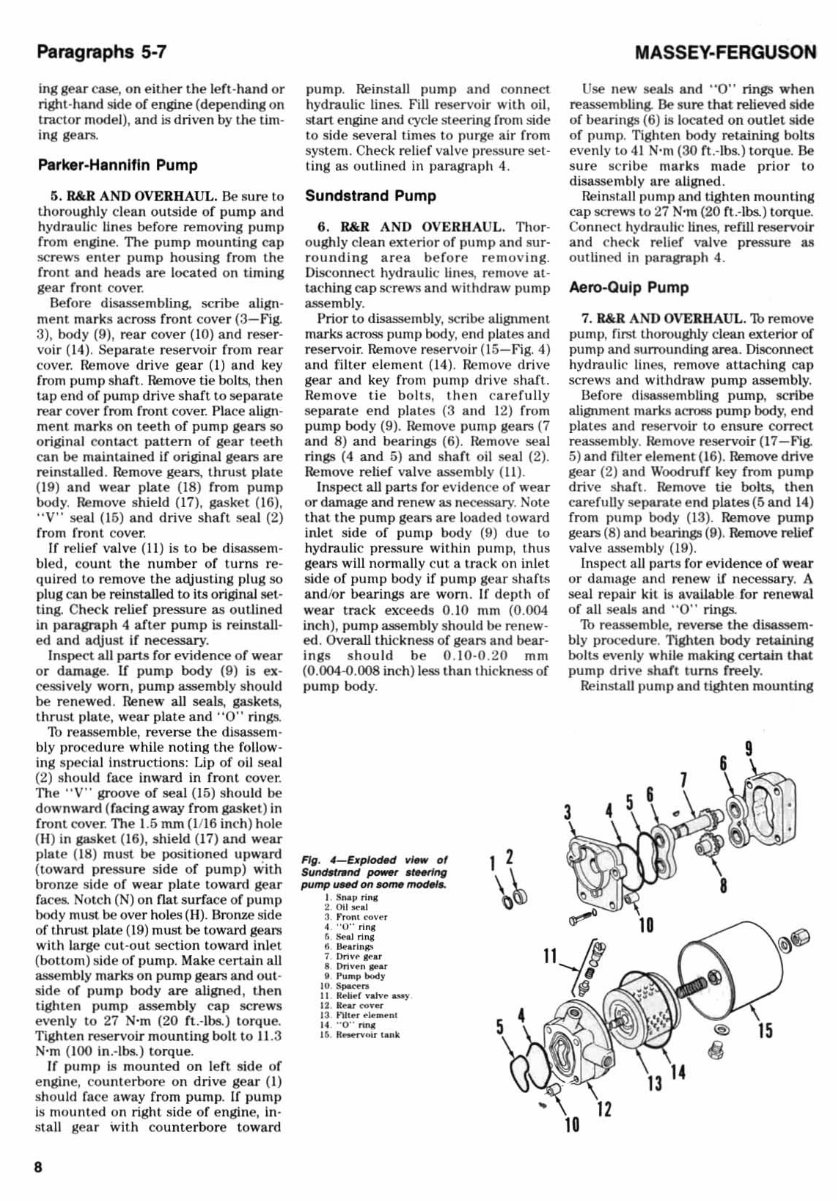
3. TIle hydrostatic power steering
fluid reservoir is attached to the rear or
the power stee ring hydraulic pump (Fig.
2). Massey-Ferguson Permatran 1lI Oil
is recommended ror use in stee ri ng
system.
On early models, an 011 strainer screen
Is located on pump Inl et pipe ins id e the
reservoir. On late models. a renewable
oil rnter element is located within the
reservoir. On a ll mod els, it is recom-
mended that stee ring fluid be renewed
and suction screen cleaned, or £ilter ele-
ment replaced, after every 500 hours or
operati on , or an nua ll y, whichever
comes £irst.
The st ee ring system Is selr bleeding,
but steering should be cycled and reser-
voir rerilled as necessary u nt il level
stops dropping. 1b £ill , stoll engine and
remove filler plug (F- Fig. 2). If st eer-
ing cy li nder has been disassembled or
drained, fill reservoir then start and idle
engine, adding fluid as level lowers un-
t il s)'8tem is stabilized. Install £iller plug
loosely, cycle the sys tem then recheck,
adding fluid as ne<:essa ry to maintain
rull reservoir. Tighten plug securely
when fluid level ceases to drop.
OPERATING PRESSURE
All Models
4. 1b che<:k power steering relief valve
pressure, fiJ~t start engine and actuate
steering until oil temperature is approx-
imately 50
0
C (120
0
F). Disconnect
pressure line ( P-Flg. 2) and conne<:t a
0-20000 kPa (0·3000 psi) pressure gage
in pump outlet port. Start engine and
operate at 2000 rpm. Relief pressure
should not exceed I L375 kPa (1650 psi).
FIg. 2-TII. ~r ., Hrlng , .... ,-voIr I. fII!«I
'"roug" hot. lor plug (F). Pump ",. .. U,.. /1M I.
MIown lit (P).
Relief valve pressure setting can be
adjusted by turning relier valve ad·
justing screw (Fig. 3, 4 or 5) clockwise
to increase pressure or cou nt erclock·
wise to reduce pressure. On early style
pump (Fig. 3) reservoir (1 4) must be
removed for access to relief valve. On
late style pum ps (Ag. 4 or 6), relief valve
is located on outs id e of pump body.
Recommended press ure setting Is
10345-11030 kPa (1600- 1 600 psi).
If specified reli er pressure can not be
obtained, service relief valve and pump
as outlined in ap llropriate paragraph 6,
6 or 7.
POWER STEERING PUMP
Three different types of power s teer·
ing pumps have been used ; Parker·
Hann ifin, Sundstrand and Aero-Qulp.
See Figs. 3, 4 and 5 f or exploded view
or each pump. The gear type stee ring
pump is attached to rear of engine tlm-
Fig. 3-uplad" vf_ of
h~-tNNllfin ~ .~.
In, pump. R.,., 10 ,..., It:N
.... mblyno, ...
L Ori~!: &e&r
2. Stoal
3. fmn. (O~~r
4. SOW
I. Pumplna: "' ...
e. Pump body
10. Rear (O~.,
II IIo:lIer ~~
13 . Fliu-r
,, -
I t. . " V" JoH.I
1II 0 .... e<
17 . Sh~ld
II. WKr ""'f
III. Thrust pIa.e
2fl. Ikn: ....
.1~'fffly' ~q
~~~CG--
7
Paragraphs 5-7
ing gear case, on eith er t he l erl-hand or
right -hand side of engine (depe nding on
tractor model ), and is driven by the tim-
ing gears.
Pa rker·Hannlfln Pump
5. R&R. AND OVERH AUL . Be sure to
thoroughly clean outside of p ump and
hydra ulic lin es before removing p ump
from engine. The pump mounting cap
screws enter pump housing from the
front and heads a re located on liming
gear fronl cover.
Before disassembling. scribe align-
ment marks across front cover (3-fig.
3), body (9), rear cover (10) and r eser·
voir (14). Separate reservoir from rear
cover. Remove drive gear (1) and key
from pump shaft. Remove tie bol ts, then
l ap end of pump dri ve shaft to separate
rear cover from front cover. Place align-
ment ma rk s on t eet h of p um p geal'S SO
original contact pattern of gear teeth
can be maintained if original gears are
reinstalled. Remove gear.i, thrust pla te
(19) a nd wear plate (18) from pump
body. Remove shield (1 7 ), gasket (16),
"V" sea l (16) and drive shaft seal (2)
from front cover.
If relief valve (II) is to be dl sasse m·
bled, count the number of turns reo
quired to remove the adjus ting plug so
plug can be reinstalled to its original set·
ting. Ch eck relief pressure as out lined
in l>aragraph 4 after pump is reinstall-
ed and adjust if necessary.
Inspect all pans for evidence of wear
or damage. II pump body (9) is ex-
cessively worn , pump assembly sh ou ld
be rene wed . Renew all seals, gaskets.
thrust plate, wea r plate and "0" rings.
Th reassemb le, reverse the djsassem·
bly procedure while not ing the fo ll ow -
in g special ins tru ctions: Lip of o il sea l
(2) should face inward in f ront cover.
The "V" groove of seal (15) should be
d ownward (facing away from gasket) in
front cove r. The 1.5 mm (I116 inch) hole
(H) in gasket (I6), shield (17) and wear
p late (18) must be positioned upward
( toward pressu re side of pump) wit h
bronze side of we ar plate toward gear
faces. Notch ( N) on nat surface of pump
body must be over holes (H). Bronze side
of thrust I)late (\9) must be toward gears
wit h large c ut·o ut section toward I nl et
(botto m) side of pump. Make certain all
assembly marks on pump gears and out·
side of pump body are aligned, then
tighten pump assembly cap screws
evenly to 27 N-m (20 ft.·lhs.) torque.
Tighten reservoir mounting bo lt to 11 .3
N'm (1 00 in .· lbs.) to rqu e.
If pump is mou n ted on lef t side of
engin e, count erbore on drive gear (I)
should fa ce away from pump. If pump
is mounted on righl side of engine, in·
stall gea r with cou nterbore toward
8
pump. Reinstall pump a nd connect
hydraulic lines. F'ill reservoir with oil,
start engine and (:ycle steering from si de
lo side several times to purge air from
system. Chec k relief valve pressure sel-
ling as outlined in paragrap h 4.
Sundatrand Pump
6. R&R AND OVERHAUL. Thor-
oughly clean exterio r of puml) a nd s ur·
ro unding ar ea be fore re moving .
Disconnect hydnlUlic Iin~ remove at ·
tachlng ca p screws and withdraw pump
asse mbl y.
Prior to disassembly, scribe alignment
marks acfOS.'iI pump body, end plates and
reservo ir. Remove rese rvoir (l5- F ig. 4)
and filter element (14). Remove d ri ve
gear an d key from pump drive shaft.
Re mo ve tie boil S, then care full y
separate end plates (3 and 12) from
pump body (9). Remove puml) gears (7
and 8) and bearings (6). rt emo\'e seal
rings (4 and 5) and shaft oil seal (2).
Remove relief valve asse mbly ( II) .
Inspect all pans for evide n ce of wear
or damage and renew as necessary. Note
t hat the pum p gears are load ed loward
inl et side of pump body (9) due to
hydraulic pressure withIn l)IIml), thus
gears will nonnall y c ut a trac k on in lei
side of pump body if p ump gear sha f ts
and/or bearings are worn . If de plh of
wear track exceeds 0. 10 mm (0.004
inch ), pump assemb ly should be renew'
ed . Overall thickness or gesr.li a nd bear·
i ngs s hould be 0. 10 -0.20 mm
(0.004"'().008 inch) less thanlhi ck nessof
pump body.
Fig. 4- E$pkxHd ",,- 0'
Su,,",~nd power ~
pump lINd on _ f1tO<HI ..
I. S ... p "n,
2.01 1..,0.1
3. ,."", <"<>v~.
4. ·· 0·· rln.
6. Se.J ring
8. ~ •• In",
7. DrI~~ ... r
S Dnv~n ... .
I p.., ... pbody
IO. ~
II 1It"lifl' nJve 0.00)'
12. II .... covet
13 . ",er .,Ioo .. .,n,
14 ··0 ·· nNI
". R-.vDl' ,ank
1 1
\ ~
MASSEY-FERGUSON
Use new seal<! and "0" rings when
reassembling. Be s ure that relieved side
of bea rings (6) Is located on outle t side
of pump. TIghten body retaining bolts
even ly to 41 N-m (30 ft .- Ibs.) torq u e. Be
su re scr Ibe ma r ks made prior to
disassembly are a li gned.
Rein.'ItaJl pump and tighten mou nting
cap screws to 27 N'm (20 rt.-lbs.) torque.
Connect hydmullc lines, refill reservoir
and check relief valve press u re as
oUllined in paragraph 4.
Aero· Qu lp Pump
7. R&R AND OVERHAUL. 1b remove
pump, first thoroughly clean exterior of
pump and surrounding area. Oi~nnect
hydraulic lines, re move au . ac hlng ca p
screws and withdraw pu mp assembl y.
Uefore dlSi\S8emhling pump, scribe
alignmelll mark. 'I acr086 pump body, end
plates and reservoir to ensure correct
reassembly. Remove reservoir ( 17 -flg.
5) and filter el eme nt (16). Remove drive
gear (2) and Woodruff key from pump
drive shaft. Remove tie bolts, th en
care fully !leparate end plates (5 and 14 )
from pump body (13). Remove pump
gears (8) a.nd bearings (9). Remove relief
valve assemb ly (19).
Inspect a ll parts for evid ence of wear
or damage and rene w If necessary. A
seal repair kit Is available fo r renewal
of all seals and ' '0·· rings.
1b reassemble, reverse. the disassem-
bly procedure. Tighten body retaining
bolts even ly while makifl8 certain that
pump drive s haft tums freely.
Reinstall pump and tighten mou nting
SHOP MANUAL
ca p screws to 27 N-m (20 ft .· lbs). Con-
nect hydraulic lines. refill reservoir and
check re lief valve ] )res..o;u re as out lin ed
in paragraph 4.
HYDROSTATIC HAND PUMP
Early Models
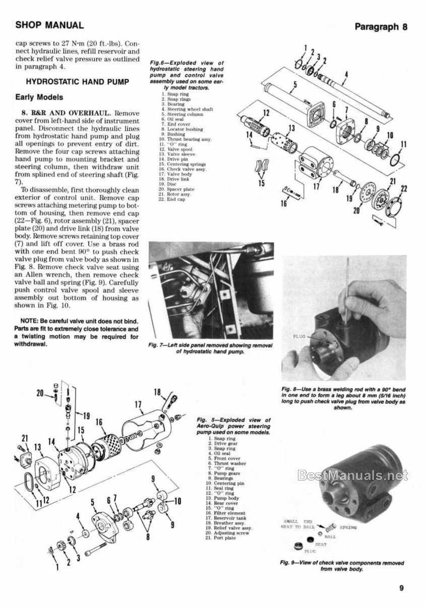
8. R&R AND OVERHAUL. Remove
cover from l eft- hand si de of inSl mmcnt
pane l. Disconnect the hydra uli c li nes
from hydros tat ic hand pump and pl ug
all ope nings to prevent e nl ry of dirt.
Remove the fou r cap screws attaching
hand pump to mounting bracket and
stee ring column, then withdraw unit
from splin ed end of stee ring sha ft (Fig.
7).
Th di sasse mble, fi rs t thoroughly clean
exterior of co nt rol uni t. Remove ca l)
screws attach ing metering pump to bot-
tom of housing. then remove end cap
(22-F'ig. 6), rotor assembly (21 ), spacer
plate (20) and d ri ve link (18) from va lve
body. Remove screws retaining top cover
(7) a nd lift off cover. Use a brass rod
with one end be nt 90
0
to push ch ec k
valve plug fro m valve body as shown in
F'ig. 8. Remove check va lve seal using
an Allen wrench , then re move check
valve ball and s pring ( 1- 1g. 9). Carefully
push control valve spool and sleeve
assembly o ut bottom of housing as
sh ow n in F'ig. 10.
NOTE: Be ca .. fu l ..... lve uni t does not bind.
PIIrtsa .. lit 10 extremely CiON tolenlrice and
• twill Ing motion may be required lor
wttlHtrawal.
FIII .6-Ellplod.d vl.w of
hydro" .IIc ,' .. rlnll h.nd
pump .nd con l rol v .,v •
• uembly uNd on ~ Hr'
I)' model t,.;ton.
\
1 Snoop rinC
2. Snoop rInp
3 lIe.n,..
t. S<H11ns ... h,...1 shall
5. S<H11ng cullimn
6. OII ... al
7. End COY"'"
8 u",a • .,.. ""'hili!!
9 U ... hlns
10 . Thrust burln' .... y
II "0" rI,..
12. '·. hoe .......
13 Valve oWve
I( Driv-e pin ,
16 Cenc"""'"""""-
16. C~k VJOl""_
17 Valve body
\8. !)rive Unk 15
19. !li te
20 8~u. pl. ce
21 Roc". uoy
2:2. t:nd cap
Fig. 1-Len ekIe pen« tMIOWd "-'"II rwnoveI
of hydtoer.tk tt.ttd pump.
Fig. S-&pIodH1 view of
MfOoOulp po,,"r " .. rlttg
pump uNd on .om. model ..
I Snail",..
2 OrIve Ie'"
3. Snap rI"I
"" ... 5 ",o,n .,.,..., r
8 ThnIIt""""r
7 "o·· .u.,
Il"ulllp~
. .... , ....
10 Cenc...u..; pin
II . SeAl oiII!L
12 ··O·' rI..,
13. !' lImp body
14 IIev <:<tv","
1&. "0" rinC
18. ntuo- ~"'~I
11 . ~"'oIrt.&l\k
II . Bre.ther _yo
19 IWILft .... Iv-e_.
20. A~...u.., ICf"eW
2 1. Pon place
Paragraph 8
I
FIg • • _U ... bfae weldlrlfl twJ"lth. fNr 0Md
In _ end /0 foro! • ,. .txHI1 • mm (SIt. Inch}
IonfI /0 pull! ctt.et ~ plug I'rom *"- body ..
....... .
FIg. f-V"" o'cMck"""'~~1"MIOWd
from VII ..... body .
9
You're Reading a Preview
What's Included?
Fast Download Speeds
Online & Offline Access
Access PDF Contents & Bookmarks
Full Search Facility
Print one or all pages of your manual
$52.99
Viewed 70 Times Today


Secure transaction
What's Included?
Fast Download Speeds
Online & Offline Access
Access PDF Contents & Bookmarks
Full Search Facility
Print one or all pages of your manual
$52.99
This manual is suitable for both first-time owners and amateur enthusiasts, as well as professional technicians. It is designed in an easy-to-read format and provides all the necessary information to perform procedures accurately. Keeping this service manual accessible and referring to it regularly is recommended. Regular and preventive maintenance outlined in the manual can help save time and money by preventing premature failure and unnecessary repairs.
- BRAKES
- CLUTCH
- COOLING SYSTEM
- DIESEL FUEL SYSTEM
- DIFFERENTIAL
- DIFFERENTIAL LOCK
- ELECTRICAL SYSTEM
- ENGINE
- FINAL DRIVE
- FRONT SYSTEM
- HYDRAULIC SYSTEM
- POWER TAKE-OFF
- TRANSMISSION
File Format: PDF
Compatibility: All Versions of Windows & Mac
Language: English
Requirements: Adobe Reader


