

Massey Ferguson MF 175 Service & Repair Manual
What's Included?
Fast Download Speeds
Online & Offline Access
Access PDF Contents & Bookmarks
Full Search Facility
Print one or all pages of your manual

MF 165 TCTOR SERVICE MANUAL
DESCRIPTION PART
Front Axle and Steering • • • • • • • • • • • • • • • • • • • " • • • • • • • • • • • • • • • • • • • • • • • • • • • • • • 1
Continental Gas Engine
• • • • • • • • • • • • • • • • • • • • • • • • • • • • • • • • • • • • • • • • • • • • • • • • • • • 2
Perkins Gas Engine • • • • • • • • • • • • • • • • • • • • • • • • • • • • • • • • • • • • • • • • • • • • • • • • • • • • • • 3
Perk ins AD4-203 Diesel Engine • • • • • • • • • • • • • • • • • • • • • • • • • • • • • • • • • • • • • • • • • • • • •
4
Dual Clutch • • • • • • • • • • • • • • • • • • • • • • • • • • • • • • • • • • • • • • • • • • • • • • • • • • • • • • • • • • • • 5
Split Torque Clutch • • • • • • • • • • • • • • • • • • • • • • • • • • • • • • • • • • • • • • • • • • • • • • • • • • • • • • 5
6 Speed Standard Transmission.............. • • • • • • • • • • • • • • • • • • • • • • • • • • • • • • • 6
8 Speed Standard Transmission ......... • • • • • • • • • • • • • • • • • • • • • • • • • • • • • • • • • • • • • 7
Multi-Power Transmission........ • • • • • • • • • • • • • • • • • • • • • • • • • • • • • • • • • • • • • • • • • • 8
Differential, Pinion and Rear Axle. • • • • • • • • • • • • • • • • • • • • • • • • • • • • • • • • • • • • • • • • • • • 9
Power Take-off • • • • • • • • • • • • • • • • • • • • • • • • • • • • • • • • • • • • • • • • • • • • • • • • • • • • • • • • • 9
Internal Hydraulic System • • • � . . . . . . . • • • • • • • • • • • • • • • • • • • • • • • • • • • • • • • • • • • • • • • 10
MASSEY-FERGU SON
GROUP IV - SETION A - PART 12
PART 12--FRONT AXLE AND STEERING-
MF 150, 165 AND 175 TRACTORS
I NDEX
Page
E NGI NE-DRIVE N STEE RI NG PUMP-
DIESEL MODEL . . . . . . . . . . . . . . . . . . . . . . . . . . . . . 2
Fi I I i ng The Reservo
·
i r . . . . . • . . . . . . . . . . . . . . . . . 2
Removing The Pump . . • . • . • . . . . . . . . . • • . . . . . . 2
I nsta l l i ng The Pum p . . . . • . . . • . . . . . • . • . . . . • . • 2
Servi ci ng The Pump-MF 150 . . . • . . . . • . . . . . . . 3
Disassembly • • • • • • . • . • • • • • • • . . . • . • • . • • • . 3
Inspection • . • • . • • • • • • • • • • • • • • • . • • • . . • • . . 3
Reassembly . . . . . . . . • • • . . . . •. . . . . . . . . . . • . . . 3
Servici ng The Pump-MF 165 and MF 175 • • • • . . 4
Disassembly • • • • • • • • • • • • • • • • • • • . • • • • • • • • • 4
I' nspecti on . • • • • • • • • • • • • • • • • • • • • • • • • • • • • • 5
Reassembly • • • • • • • • • • • • • • • • • • • • . • • • • • • • • • 6
ENGINE-DRIVE N STE ERI NG PUMP-
GASOLI NEOD EL • • . • • • . . . • • • • . . . . • . • . • . . . 6
Fil l i ng The Reservo ir . . • • . . • • • • . • • • • • • . • • . • . 6
Removal . • • • • • • • • • • • • • • • • • • • • • • • • • • • • • • • • • 6
Disassembly . . • • • • • • . • • • • • . • • • • • • • • • • • • • • • • 6
Inspection . • • • • . • . . • • • • • • • • • • • • . • • . • • • • • • • 7
Reassemb I y . . • • • • • • • . • • • • • • • • • • . • . • • • • • • • • • 7
Installation . • • • • • • • • • • • • • • • • • • • • • • • • • • • • • • 8
HYDRAULIC CYL I N DER A N D VALVE . • • • • . • . • • .
Removal . • • . • • . . . . . • • . . • • . • • • • . • • • • . • • . • . •
MF 165 a nd MF 175 Row Crop Models . • • . . • .
MF 150 Row Crop and MF 150 and MF 1A
Dual Tricy cle Models . • • • • . . • . . . • . • • . • . . •
Disassembly-Contro l Va l ve • . • • . • . . • . • • • • . • . .
Insפcti on-Contro l Va l ve . • • • . • • . • • • • • • . . • • o
Reassemb l y-Contro l Va l ve • . • . • • . • . • • • • • • • .. •
D isassem bly-Cy l i nder . • • • • . • • . • . • • . • • • • • • • •
I nspection-Cylinder · · · · · · · · · � · · · · · · · · · · · · ·
Reassemb I y :Cy I i nder . • • • • • • • • • . • • . • • • . • • • •
I I
"
I nsta at i on :· • • • • • • • • • . • • • • • • • • • . • • . . • • • • • . .
8
8
8
10
10
1 1
1 1
11
12
12
12
MF 1A and MF 175 Row Crop Models . • • • • • . 12
: MF 150 Row Crop and F 150 and
MF 165. Dua l Tricycle Models • • • • • • • • • • • • • • 13
PEDESTAL SHAFT . • • • • • • • • • • • • • • • • • • • • • • • • • • • 13
MF 165 and MF 175 Row Crop Models . • • • • • • . • 13
Remove I • • • • • • • • • • • • • • • • • • • • • • • • • • • • • • 1 3, 14
Inspection • • • • • • • • • • • • • • • • • • • • • • • • • • • • • • 14
Page
Instal lation . . . . . . . . . . . • • . . . . . . . • . . . . . • . 14
MF 150 Row Crop and MF 150 a nd
MF 165 Dual Tricycle Models . . . . . • . . . • . . . . . 15
Remo va l . • • • • • • • • • • • • . • • . • • • • . • . • • . • • . � 15
Disassembly . . . • • • . • . . . . . . • . . . • . . . . . . . . . 15
I nspection . . . • • . • • . • • • • . • • . • • • • • � • • . . . . 16
Reassembly . . • • . • . . • . • • • • . . . • . . • • . • . . • . • 16
I nstal lation . . . • • • . . . . • • • . • • . . • • . • o . . . . . . 16
SERVIC I NG THE STE ERI NG GEAR HOUSI NG . . • 17
Prerations For Servicing Steeri ng
Gear Housi ng • • • • • • • • • • • • o • • • • • • • • • • • • • • • o 17
Completi ng Tractor Reassembly . • • • . • • • • • . . . • 19
Disassembl i ng The S.teeri ng Gear Housi ng . • • • . 21
Reassembl i ng The Steer ing Gear Housing . • . . . 21
SERVIC I NG THE FRON T AXLE . . • • . . o . . . . . . . . . 22
MF 150 Row Crop Model s • • . • . • • . • • • • • • . • . • 22
Removal . • • . • • • • • • • • • • • • • . . • • • • • • • • • • . • 22
I ns pect i o n . • • • • • . • • • , • • • • • • . • • • • • • . • • • • • 23
Instal lation . • . • • . • • • • • • • • • • • • • • • • •. • • • • . • 23
MF 165 and MF 175 Row Crop Model s . .. • • • o . . 23
Removal and Insta l lation . . • . • . . . . • • • . . . . . 23,24
Dua Tricycle Models . . . . . • • • . . . • • . • • • • • • • • 25
Removal . • . • . • • • . • • • • • • • • . • • . • . • • . • . . .
25
Disassembly............................. 25
Reassemb I y • • • • • • • • • • • • • • • • • • • . • • • • • • • • •
25
l n-s ta I I at ion • • • • • • • • • • • • • • • • • • • • • • • • • • • • 26
ADJ USTME NTS • • . • . • • • . . • • • • . • • . . . . • • . . • • • . . 26
Toe-In • • • • • • • • • . - . . . . . . . . . . . . . . . . . . . . . . . 26
Drag Link • • • • • • • • • • • • • • • • • • • • • • • • • • • • • • • • 26
Steering Axl e Wheel Bearings-Row Crop Models 27
Ste edng Axle Wheel Bearings-
Dual Tricycle Models . • • • • • • • • • • • • • • • • . • • • • 27
Axle Pivot Pin End-Play- MF 150 • • • • • • • • • • • 27
Axle Pivot Pin End-P iay-MF 1A and MF 175 • 27
Steering Gear Housing • • • • • • • • • • • • • • • . .
·
• • • • 28
Steering Valve • • • • • • • • • • • • • • • • • • • • • • • • • • • • 28
SPECIF ICATIONS • • • • • • • • • • • • • • • • • • • • • • • • • • • 29
TRO UBLE-SHOOTING . . . . . . ... . . . . . . . . . . . . . >
This Part of the Mual contains the recommended removal, overhaul and installa-
tion procedures at should be ten when servicing the steering system on the MF
150, 165 and 175 Tractors.
termine the possible cause of any malfuncon by consulting the "Trouble-Shoot-
ing" Section of is Manual befe any attempt is made to repair the system. Follow-
ing this practic will result in more accurate· maintenance, of the stee· rtng system d
will aid in-preventing uecessary repairs.
Printed in U.S.A.
1
.
.
M A S S E Y - F E R G U S O N
MF 150, 165 & 175 TRACTORS
ENGINE-
DRIVEN ST EERING PUMP-
Diesel Mode
l
FILLING THE RESERVOIR
1. Position front wheels in a straight for-
ward directi0n and shut off engine.
2. Remove fil ler plug and fill reservoi r with
oil conforming to MF Specification M-1110 un-
til oil level is even with the filler opening.
3. Replace filler plug, start engine and
operate s teering wheel in both directions to
insure the entire system is filled.
4. Position front wheels in a straight for-
ward direction and shut off engine.
5. Repeat these operations until the oil level
remains even with the fil ler opening.
REMOVING THE PUMP
1. Position front wheels in a straight for-
ward direction and shut off engine .
2. sconne ct hydra u 1 i c lines, remove
mounting bolts, remove pump from Tractor
and plug ports d lines.
3. Remove pump mounting gasket from tim -
ing gear housing (or mounting surface of pump)
and thoroughly clean the mounting surfa ces.
2
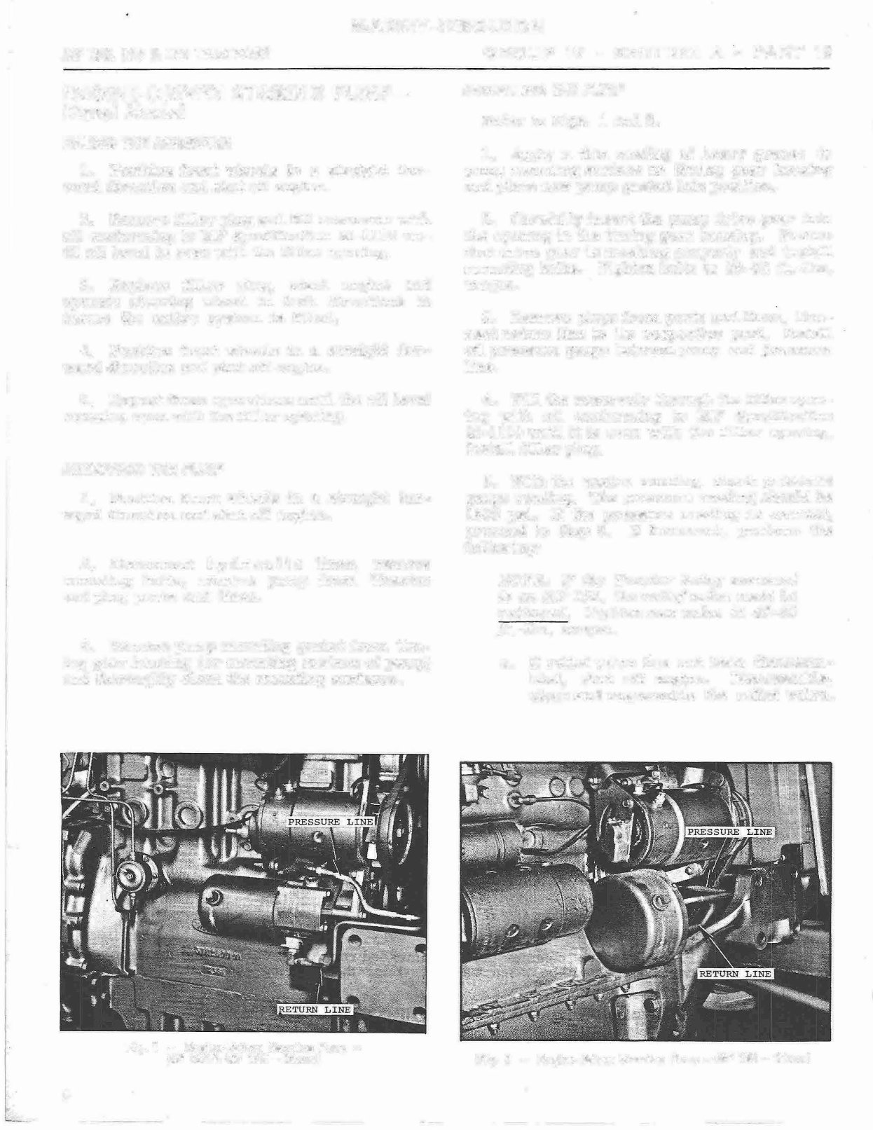
Fig. 1 - Engine-Driven Steering Pump -
MF 1 65 & MF 17 5 - Diesel
GROUP IV - SECTION A - PART 12
INSTALLING THE PUMP
Refer to Figs. 1 and 2.
1. Apply a thin coating of heavy grease to
pump mounting surface on timing gea r housing
and place new pump gasket into position.
2. Carefully inse rt the pump drive gea r into
the opening in the timing gear housing. Ensure
that drive gear is meshing properly and install
mounting bolts. Tighten bolts to 28-32 ft.-lbs .
torque.
3. Remove plugs from po rts and lines. Con-
nect return lihe to its respective po rt. stal l
oil pressure gauge between pump and pressure
line.
4. Fill the rese rvoi r through the fille r open-
ing with oil conforming to MF Specification
M-1110 unl it is even with the filler opening.
stall filler plug.
5. Wi the engine running, check p ressure
gauge reading. The pressure reading shoul d be
1500 psi. the pressure reading is co rrect,
proceed to Step 6. incorrect, perform the
following:
NOTE: the Tractor being serviced
is an MF 150, the relief valve must be
replaced. Tighten new valve to 40-50
ſt. -lbs . torque.
a. relief valve has not been sassem-
bled, shut off eng�ne. sassemble,
, clean and reassemble the relief valve.
Fig. 2 - Engine-Driven Steering Pump - MF 1 50 - Diesel
M A S S E Y - F E RG U S ON
GROUP IV - SE. CTION A - PART 12
FRONT AXLE & STEERNG
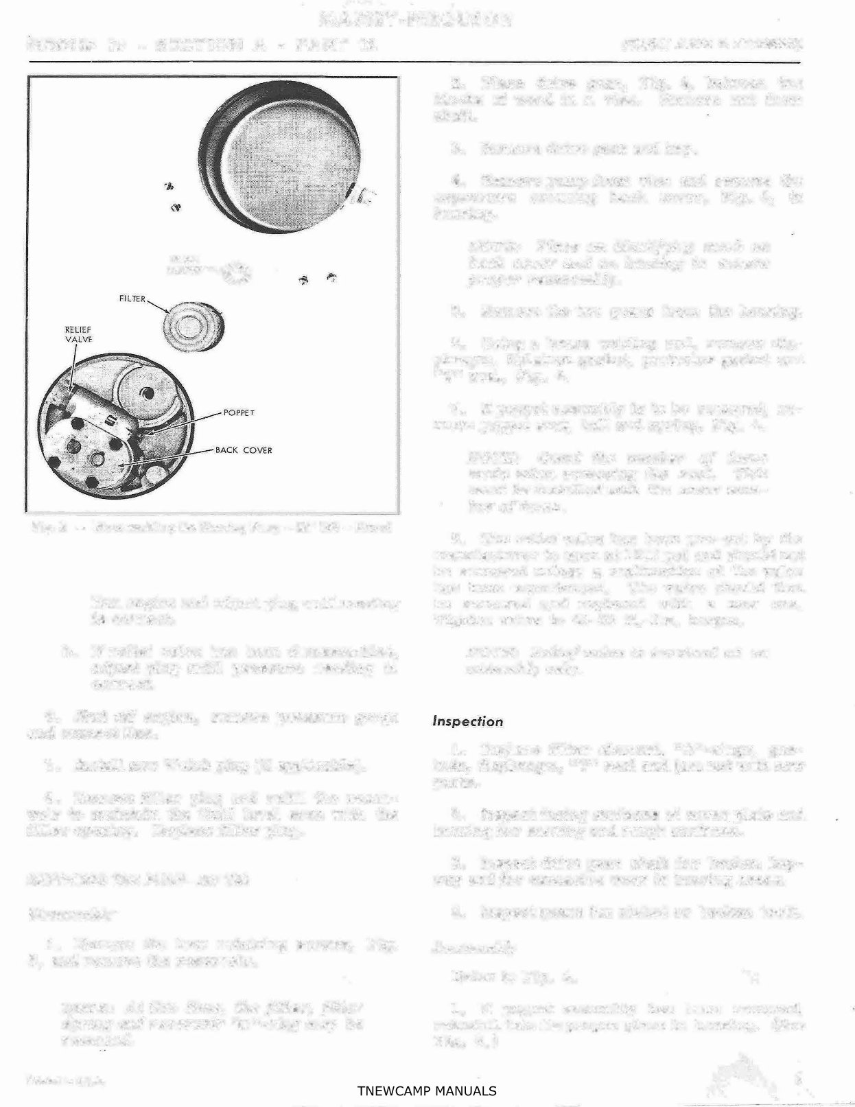
FILTER
SPRING
Fig. 3 - Disassembling the Steer ing Pump - MF 150 - Diesel
Run engine and adjust plug until reading
is cor rect.
b. relief valve has been disassembled,
adjust plug until pressure reading ts
correct.
6. Shut off engine, remove pressure· gauge
and connect line.
7. stl new Welch plug (if applicable).
8. Remove filler plug d refill the reser-
voir to maintain the fluid level even with th�
filler opening. Replace filler plug.
SERVICING THE PUMP-MF l50
Disassmbly
·
1. Remove the four retaining screws, Fig.
3, and remove the reservoir.
NOTE: At this time, the filter, filter
•
spri and reservoir '�0 "-ring may be
removed.
Printed in U.S.A.
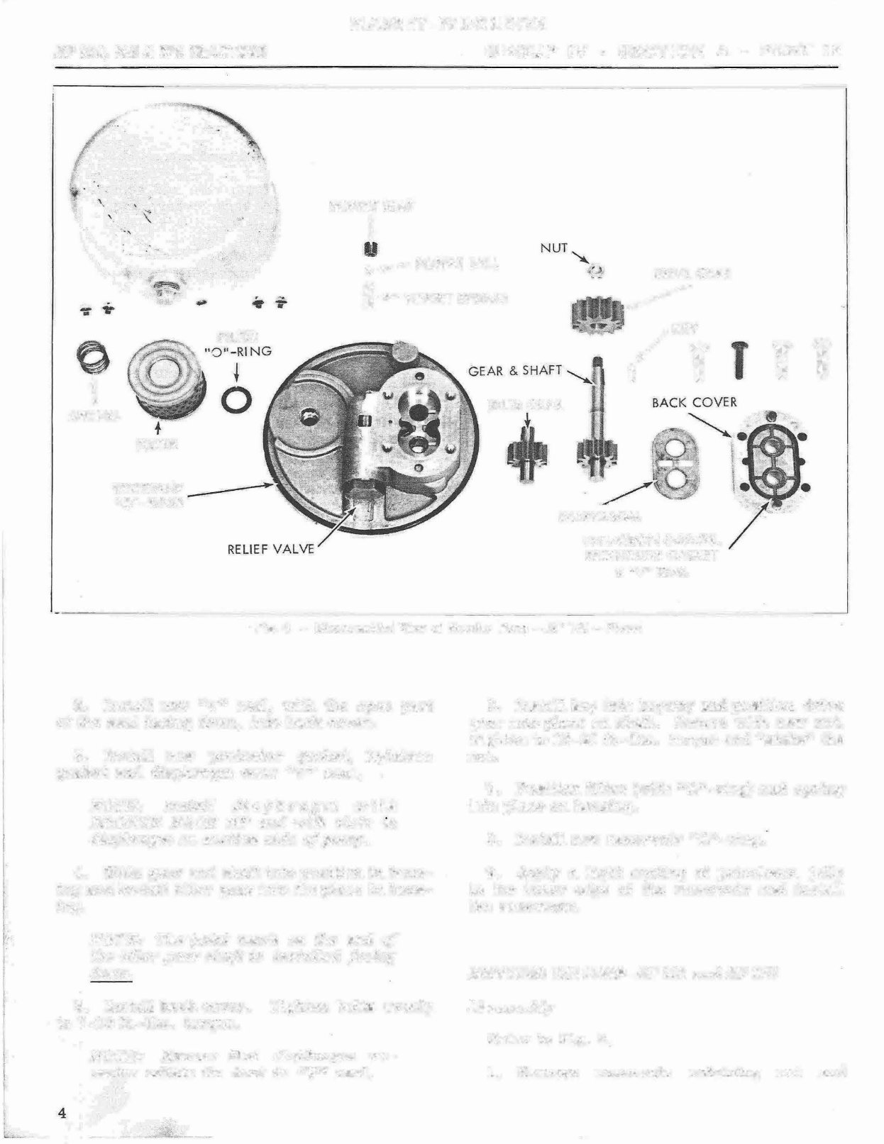
_ 2. Place drive ger, Fig. 4, between t wo
blocks of wood in a vise. Remove nut fr om
shaft.
3. Remov e drive gear and key.
4. Remove pump from vise and remove the
capscrews securing back cover, Fig. 4, to
housing.
NOTE: Place an identifying mark on
back cover and on h ousing t o ensure
proper reass embly.
5. Remove the o gears from the housing.
6. Using a brass welding rod, remove dia-
phragm, Nylatron gasket , protecto r gasket d
"V" seal, Fig. 4.
7. poppet assembly is t o be rem oved, re-
move poppet s eat, bl d spring; Fig. 4.
NOTE: Count the number of
made when removing th e s eat.
must be ins talled Wfh the same
ber of tus.
turns
This
num-
8. The relief valve has been pre-set by the
manufacture r to open at 1500 psi and should not
be removed unless a malfunction o£ the valve
has been eerienced. The valve should then
be removed and replaced wi a new one.
Tighten valve to 40-50 ft.-lbs. torque.
NOTE: Relief valve is serviced as an
assembly onl y.
1. Replace filter element, "0" -rings, gas-
kets, diaphragm, "V" seal and j nut with new
parts.
2. spect facing surfaces of cov er plat e d
housing f or scoring and rough surfaces.
3. spect drive gear sht for broken key-
way and _ for excessive wear in b earing areas.
4. spect gears for nicked or b oken teeth.
Reassembly
Refer to Fig. 4.
1. poppet . assembly has been removed,
reinstall into its proper place in housing. (See
Fig. 3.)
3
MASSEY-FERGU SON
MF 150, 165 & l75 TRACTORS GROUP IV - SECTION A - PART 12
POPPET SEAT
�
�- POPPET BALL
DRIVE GEAR
I POPPET SPRING
�
0
t
SPRING
F\ LTER
RESERVOl
"0"-RING
FILTER
IDLER GEAR
, / KE
T
T T '
DIAPHRAGM
NYLATRON GASKET1
PROTECTOR GASKET
& ''V" SEAL
Fig. 4 - Oisa· ssembled View of Steering Pump - MF 1 2 - Diesel
2. stall new "V" seal, with the open part
of the seal facing down, into back cover.
3. stl new protector gasket, Nylatron
gasket d diaphragm over "V" seal.
NOTE: Ins ta ll diaphragm with
BRONZE FACE UP and with slots z
diaphragm on suction side of pump.
4. Slide gear and sht into position in hous-
ing and instl i dler gear into its place in hous-
ing.
NOTE: The paint mark on the end of
the idl er gear shaſt s installed facing
down .
5. stl back cover. Tighten bolts evenly
7-10 ft.-lbs . orque.
4
NOTE: Ensure that diaphragm re-
mains ithin ts seat in "V seal.
6o tall key into keyway and poSit ion drive
gear into place on sht. Secure with new nut.
Tighten to 15-20 ft.-lbs. torque and '·'stake" the
nut.
7. Posion filter (with "0'' - ring) d spring
into place on housing.
8. stall new reservoir "0" -ring.
9. Apply a light . coating of petroleu jelly
to the inner edge of the rese rvoir and install
te reseroi r.
SERVICING THE PUMP-MF 165 and MF 175
Disassembly
Refer to Fig. 5.
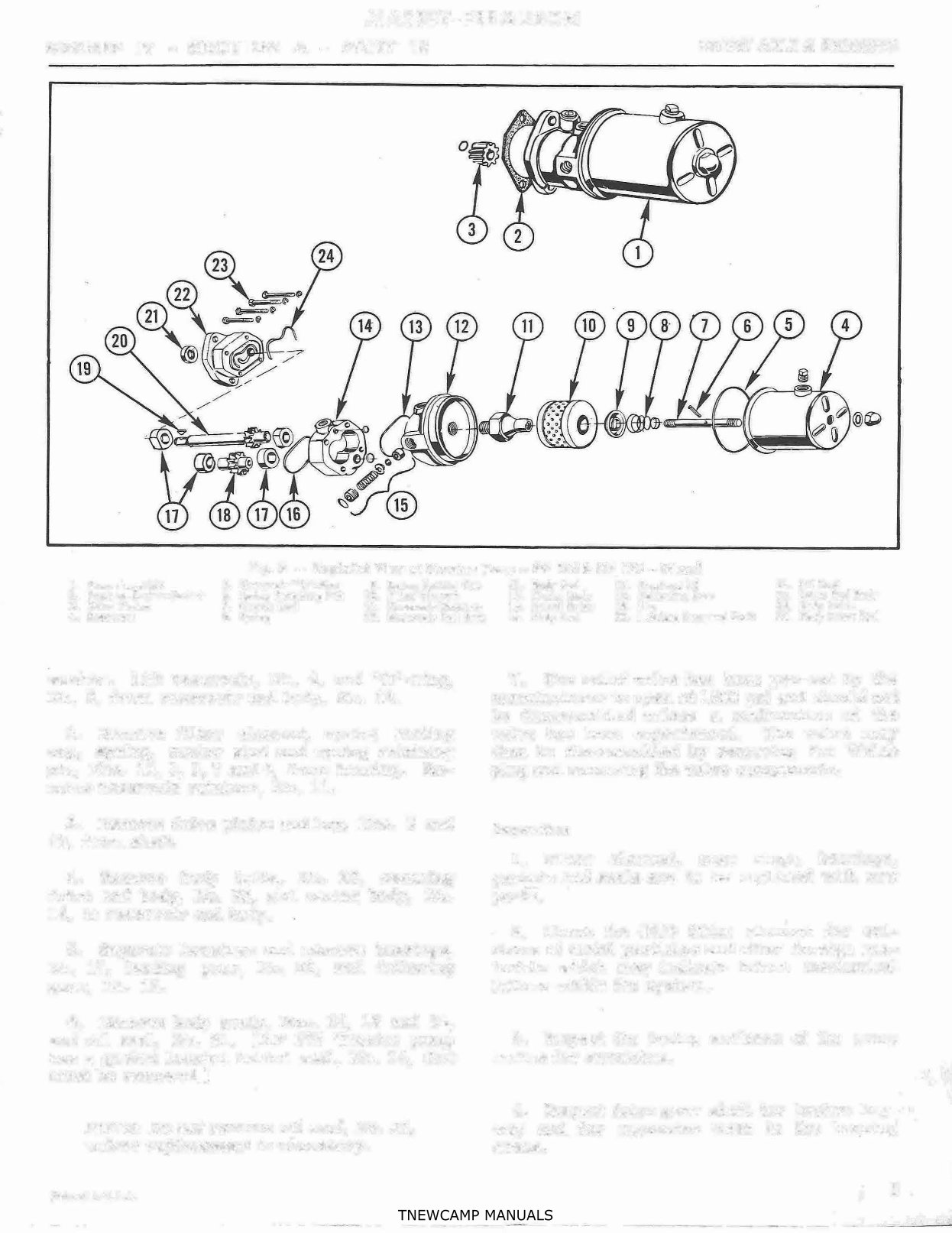
1. Remove reservoi r reaining nut d
MA S S E Y -FERGUSON
GROUP IV - SECTION A - PART 12
FRONT AXLE & S TEERING
F i g . 5
-
Exploded View of Steer ing Pump - MF 165 & MF 175 - D iesel
1. Pump As sembly 5. Reservoi r "0"-Ring
9. Spring Seating Cup
2. Pump-to -Engine Gasket 6. Spring Reta ining Pin 1 0. Filter E lement
3. Drive Pin ion
7. Center Stu d 11. Reservoi r Retaine r
4. Reservoir 8. Spring 12. Reservoi r End Body
washer. Lift reservoir, No. 4, and "0" -ring,
No. 5, from reservoir end bo dy, No. 12.
2. Remove filter element, spring seang
cup,
.
spring, center stud and , spring retaining
pin, Nos. 10, 9, 8, 7 and 6, from housing. Re-
move reservoi r retainer, No. 11 .
3 . Remove drive pinion and key, Nos. 3 d
19, from shaft.
4. Remove body bolts, No. 23, securing
drive end body, No. 22, and center body, No.
14, to reservoir end body.
5. Separate housings and remove bearings,
No. 17 , leading gear, No. 20, and following
gear, No. 18.
6. Remove body seals, Nos. 13, 16 and 24,
and oil se, No. 21. (MF 175 Tracr pump
has a gasket located behind seal, No. 24, that
must be removed. )
NOTE: Do not remove oil seal, No. 21,
unless replacement is necessary.
P rinte d in U.S .A.
13. Body Se ol 17. Bearings (4) 21. Oil Sea l
1 4. Center Body 18. Fol lowing Gear 22. Drive End Body
15. Reli ef Va l v e 19. K 23. Body Bolts
16. Body Seal 20. Leadig Gear and Shaft 24. Body Front Seal
7 . The relief valve has been pre-set by the
manufacturer to open a t 1500 psi and shoul d not
be disassembled unless a malfunction of the
vve has been eerienced. The valve may
then be disassembled by removing the Welch
plug d removing the valve components.
Inspection
1. Filter element, snap rings, bearings,
gaskets and ses are to be replaced with new
parts.
2. Check the OLD filter elem
.
ent for evi-
dence of metal p articles and o ther foreign ma-
terials which may indicate fure mechical
failure within the system.
3. spect the facing surfaces of e pump
bodies for scratches.
4. spect drive gear sht for broken key-
wa
y and for excessive wear in the be�ring
areas.
5
MA S S E Y -FERGUS · ON
MF 150, 165 & 175 TRACTORS
Reassembly
Refer to Fig. S.
1. Apply a light coating of Permatex #3
form-a-gasket to bore of le ad gear shaft se al
in drive end body, No. 22. Press new seal i nto
position (flush to surface of bore) d stake in
three places.
NOTE: Omit this procedure if seal
was not removed.
2. stl new ses, Nos. 13, 16 nd 24.
NOTE: MF 1 75 is being serviced,
a new gasket must be installed behind
seal, No. 24.
3. stal l new bearings, No . 17 , leading
gear, No . 20, and fol lowing gear, No. . 18.
Place pump bodies, Nos. 22, 14 and 12, in
their proper sequence and install bolts, No. 23.
4. stl drive pinion and key, Nos. 3 and
19, onto sht, No. 20.
5. sll reservoir retainer, No. 11. Po-
sition filter element, No. 10, spring seating
cup, No .• 9, spring, No. 8, and spring retning
pin, No. 6, in place on center sd, No. 7, and
install stud into reseoir retner, No. 11.
6. stall new "0"-ring, No. 5, and positio n
reservoir onto reservoir end body. stl re-
taining nut and washer.
7. the relief valve assembly, No. 15, has
been removed, reinstall the assembly;. less the
Welch plug. (Final adjustment is to be made
during test. )
8. Rotate the drive gear by hand check
for freedom of movement. The pp should
have a ce
·
rfaih amount of drag but should rotate
freely ter a shor t period of rning.
ENGIN E-DRIVEN STEE RING
PUMP-Gasoline Model
FILLING THE RESERVOIR
l. Posion front wheels in a straight for-
ward direcon d shut off engine.
2. Re
.
move reservoir cover and fill reser-
voir wi oil coorming to MF ecification
6
GROUP IV - SE· CTION A - PART 12
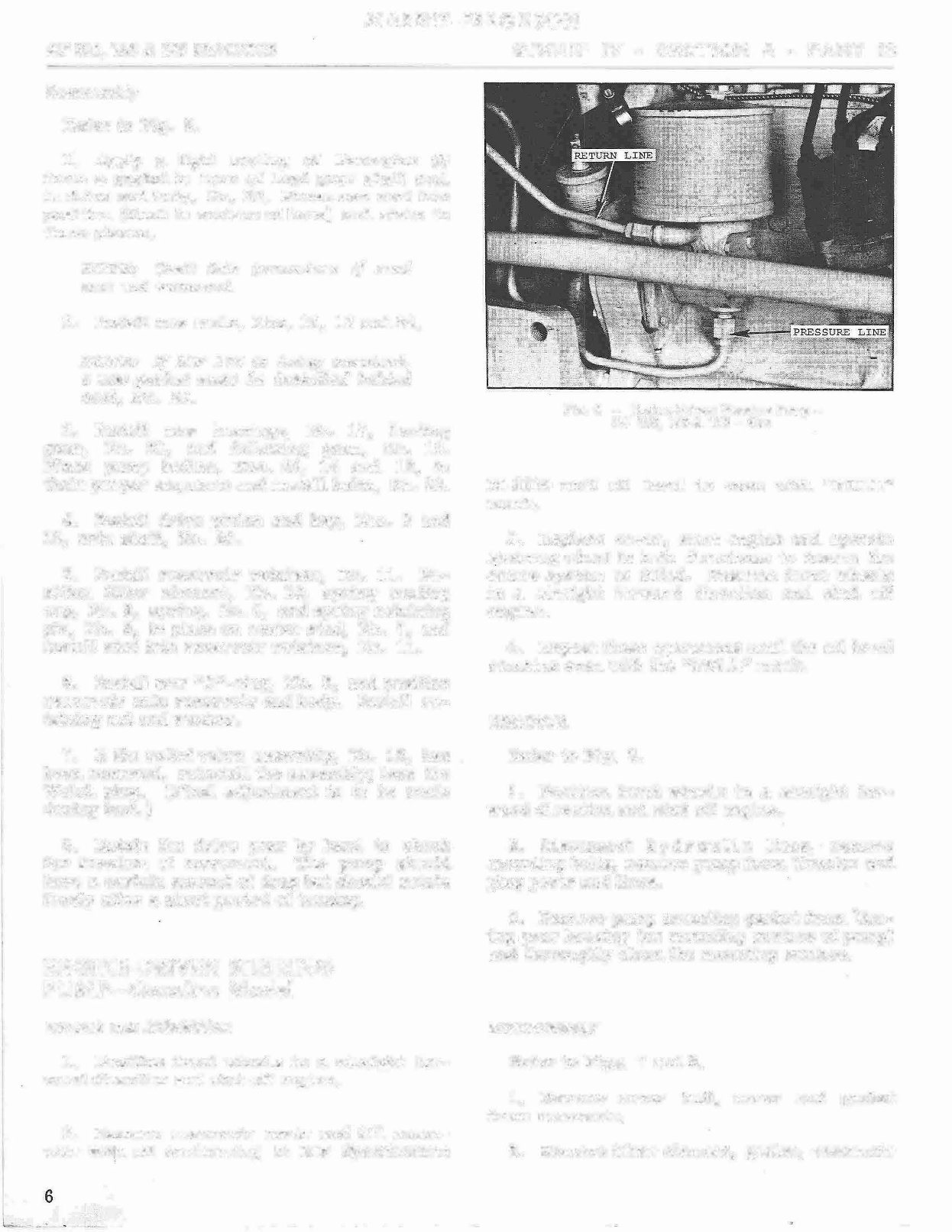
Fig. 6 - Engine-Driv- en Steering Pp -
M F 1 50, 16 5 & 17 5 - Ga s
M�11l 0 until oil leve l is even with "FULL''
mark.
3. Replace cover, start engine d operate
steering wheel in both recons insure the
entire system is filled. Posit ion front wheels
in a straight forward direction and shut off-
engine.
4. Repeat these operations until the oil level
remains even with the "FULL" mark.
REMOVAL
Refer to Fig. 6.
1. Position fro nt wheels in a strght for-
ward direction and shut off engine.
2. Disconnect h y d r u 1 i c lines,
·
remove
mounting bol ts, r
·
emove pump from Tractor and
plug ports d lines.
3. Remove pump m- ounting gasket from 'm-
ing gear hous ing (or mounting surface of pump)
and thoroughly cle the mounting surface.
DISASSEMBLY
Refer to Figs. 7 d 8.
1. Remove cover bolt, cover d gasket
from reservoir.
2. Remove filter element, gasket, reservoi r

MASSEY-FER · GUSON
GROUP IV - SECTION A - PART 12 FRONT AXLE & STE
·
ERING
FI_LTER
"0"-RING'
SERVOIR J
SEAT •CORE /
I/,
0
t
Gl�ST
RESERVOIR
I
Fig. 7 - DisQssembling the Steering Pump -
M 150, 165 & 175-
·
Gas
seat core, the capscrew securing the reservoir
to the pump body and t he reservoir.
3. Remove "0"-ring, spring d hl from
housing.
4. Plac· e pump body in a holding fixture d
remove nut from drive . gear sht. Remove
drive gear and key.
5 . Remove bolts securing front plate to
housing. Separate front plate from housing and
remove idler gear and lead gear d shaft as-
embly.
6. Remove diaphragm. Remove spring and
bl from suction side of front plate.
7 . Remove back-up gasket, gasket protector
and diaphragm seal from f ront plate.
B. the lead gear s ht oil seal shows evi-
dence of leakage, remove the se from e
front plate.
9. The relief valve has been pre-set by the
m anuf acturer to open at 1500 psi and hould not
be removed unless a malfunction of e valve
has been eerienced. It will then be necssary
to remove the relief vve and ins tall a new
one. Tighten to 40-50 ft. -lbs. torque upon in-
sl laon.
NOTE: Relief valve is servied as an
assembly an.Zy .
Printed in U.S.A.
GAST
DRIVE
GEAR
HOUSING
FRONT P.TE
BA- LL
�
�
SPRING/ �
DIAPH�GH
REli�F
VAL
Fig. 8 - Di sssebled View of Steering Pump -
MF 150� 165 & 17 5 - Gas
INSPECTIO N
1. Replace filter e lement, gaskets, ses,
diaphragm, "0" -Fings, and spring and ball,
Fig. 8, with new par ts.
2. spect facing surface s of front plate and
housing for scratches.
3. spect drive gear an d shaft for broken
keyway.
4. Check the OLD filter e lement for evi-
dence of meal p articles and other foreign ma-
terials wnich may incate fur e mechanical
failure within the sy stem.
REAS SEMBLY
Refer to Figs. 7 d 8 .
1. Apply a light coating of Permatex #3
form-a-gasket to bore of lead gear shaft seal
in front plate. Press new seal into posion
( flush to surface of bore ) and stake in three
places.
NOTE·: Omit this procedure if s ea l
was not removed.
2.. stall new diaphragm se into front
plate wi th the "open" par t of the se facing the
ORNE GEAR.
3. stall new gasket protector, fo l lowed by
new back-up gasket, over diaphragm seal :
7
MASSEY-FERGUSON
MF 150, 165 & 175 TRACTORS
4. Drop new ball and new spring into hole on
sctian side of front plate and place new dia-
phragm on top of gasket.
NOTE: The two notches in diaphragm
rnust go on suction side of pump and
bronze side of diaphragm 1nust face
upward.
5. stall lead gear and sht into front plate
d place ier gea r into front plate with paint-
ed (or marked) end of shaft tow ard the DRE
GEAR.
6. Install front plate. Tighten bolts evenly
to 7 -10 ft. -lbs. torque.
NOTE: Ensure that diaphragm re-
nwins within its groove in front pla te.
7. stall new "0" -ring, Fig. 7, bal l and
spring.
B. stal l reservoir seat core and gasket
onto reservoir. Fasten reservoi r onto housing
with caps crew and w asher. Tighten core and
capscrew to 10-15 ft. -lbs. torque.
9. stall key into its groove and sl ide drive
gear over shaft. Instal l nut and washer. Tight-
en to 15-20 f t.-lbs . torque.
10. Rotate the drive gear by hand to check
for freedom of movement. The pump should
have a certain amount of drag but should rotate
f _ reely after a short period of turning.
INSTALLATION
Refer to Fig. 6 .
1 . Apply a thin coating of heavy grease to
pump mounti ng surface of timin g gear housing
d place new pump gasket into pos ition.
2 . Carefully inse rt the pump drive gear into
e opening in e timing gear housing. Ensure
that drive gea r is meshing prope rly d install
mounting bolts. Tighten to 30-35 ft.-lbs.
torque.
3. Remove plugs from ports and lin es. Con-
nect rern li ne to its r espective port. Tighten
to 20-30 f t.-lbs. torque. sl l oi l pressure
gauge bee en pump d pressure line.
4. stl new fil ter elment ad fill rese r-
voir w i oil coorming to MF ecification
8
GROUP IV - SECTION A - PA RT 12
M-1110 until oi l level is even with the "FULL"
mark. Install reservoir cover.
5. Start engine a nd turn steering wheel to
extreme left and right. Shut off engine and re-
check oil level. It must remain at the "FULL"
m ark.
6. With engine running, che ck pressure
gauge reading. The pressure reading should be
1500 psi. the pressure reang is correct
proceed to Step 7. incorrect, remove the
relief valve and i nstal l a new one. Tighten
valve to 40-50 ft. -lbs. torque .
7. Shut off engine and remove pressure
gauge. Connect pressure line. Tighten to 20-
30 ft.-lbs . torque.
8. Remove reservoir cover to check for
correct fluid leve l. Maintain fluid leve l even
with "FULL" mark. Replace reservoir cover.
HYDRAULIC CYLINDER AND VALVE
REMOVAL
MF 165 and M
.
F 175 Row Crop Models
Two different pes of stee ring arrangements
are used on the MF 165 and MF 17 5 Tractors
having e Row Crop front axle. Therefore the
removal, instlaon and adjustment proce-
dures of e cylinder and vve wil l dfer. Re-
fer to Figs. 9 and 1 1, which show these o
steering arrangeme nts and follow the approp ri-
ate procedures fo r the Trac tor being se rviced.
ARR ANGE.MENT AS SHOWN IN FIG . 9
Refer to Figs. 9 d 10.
1. Remove grille door, gril le d side
panels.
2. sconnect hoses, Nos. 2 and 3 . Plug
ports.
3. Remove cotter pin and clevis pin, No. 5,
securing ste ering arm link,
·
No 4, to the upper
steering arm, No. 9.
4. sconnect drag li nk, No. 8, and remove
snap ring, No. 11.
5. Remove upper arm from pedestal shaft.
You're Reading a Preview
What's Included?
Fast Download Speeds
Online & Offline Access
Access PDF Contents & Bookmarks
Full Search Facility
Print one or all pages of your manual
$39.99
Viewed 16 Times Today


Secure transaction
What's Included?
Fast Download Speeds
Online & Offline Access
Access PDF Contents & Bookmarks
Full Search Facility
Print one or all pages of your manual
$39.99
Massey Ferguson MF 175 Service & Repair Manual
When it comes to fixing problems on your tractor, this repair manual provides a comprehensive, step-by-step approach. It includes troubleshooting and replacement procedures, along with clear images and exploded-view illustrations, making it useful for both professional mechanics and DIY enthusiasts.
Regular maintenance is essential for the durability of your tractor. Over time, certain parts will wear out and require replacement. A good tractor repair manual offers manufacturer-recommended troubleshooting charts and replacement procedures, enabling you to save on repairs, reduce downtimes, and maintain your tractor effectively.
Please note:
- This is not a generic repair manual. It contains every troubleshooting and replacement procedure provided by the manufacturer, including step-by-step instructions, exploded-view illustrations, and clear images.
- No need to flip through hundreds of pages to find specific information. It is easily accessible and searchable, making it more convenient than a traditional bound manual.
- Printable: Yes
- Language: English
- Compatibility: Compatible with various electronic devices, including PC, Mac computers, Android and Apple smartphones, and tablets.
- Requirements: Adobe Reader (free)


