Massey Ferguson MF135 MF148 Tractor Service & Repair Manual
What's Included?
Lifetime Access
Fast Download Speeds
Online & Offline Access
Access PDF Contents & Bookmarks
Full Search Facility
Print one or all pages of your manual
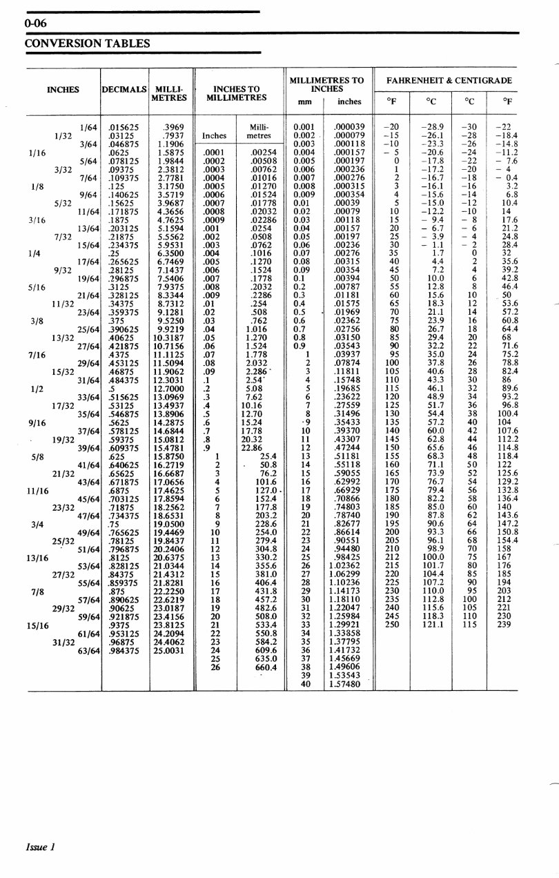
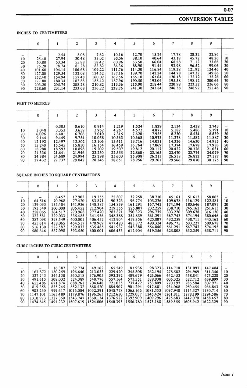
ecomanual.me 0-01 INTRODUCTION INTRODUCTION INTRODUCTION AMENDMENTS GENERAL INSTRUCTIONS CONVERSION TABLES SPECIAL TOOLS INTRODUCTION This Workshop Manual which is in loose leaf form for easy amendment, has been compiled to assist Massey-Ferguson Distributor and Dealer personnel to undertake routine maintenance and servicing, minor and major repairs, replacements, adjustments and out of season storage efficiently by the most straight forward method. With this aim in mind, the Manual is divided into parts and sections, and each page bears the part and section number. This will make the required subject easier to find and the numbered operations will simplify cross reference. REPAIRS AND REPLACEMENTS When service parts are required it is essential that only genuine Massey-Ferguson replacements are used. Attention is particularly drawn to the following points concerning repairs and the fitting of replacement parts and accessories. Safety features embodied in the tractor may be impaired if other than genuine parts are fitted. In certain territories, legislation prohibits the fitting of parts not to the tractor manufacturers specifi¬ cation. Torque wrench setting figures given in the Workshop Manual must be strictly adhered to. Locking devices, where specified must be fitted. If the efficiency of a locking device is impaired during removal it must be renewed. The tractor warranty may be invalidated by the fitting of other than genuine Massey-Ferguson parts. All Massey-Ferguson replacements have the full backing of the factory warranty. Massey-Ferguson Distributors and Dealers are obliged to supply only genuine service parts. Special Tools The use of special tools mentioned in the text contributes to an efficient and profitable repair. Some operations are, in fact, impracticable without their use, particularly those, for example, which deal with the assembly of the differential unit. Distribu¬ tors are therefore urged to check their tools against the list provided and order those necessary from: V. L. Churchill & Co. Ltd., London Road, Daventry, England. Schedule of Repair Operations The operations listed in the Repair Time Schedule refer to those described in this manual. The time set against each operation in the schedule is evolved by performing the actual operations on a standard tractor using special tools where stated. The Repair Time Schedule for use with this manual, is issued as a separate publication. NOTE - SERVICE INFORMATION SHEETS AMENDMENT SHEETS AND REPAIR TIME SCHEDULES ARE ISSUED TO THE MASSEY- FERGUSON DISTRIBUTORS AND DEALERS ONLY AND ARE NOT FOR GENERAL PUBLI¬ CATION Service Tools and Equipment Where the use of a Service Tool is specified in an operation the tool number will be shown under the operation heading and also following the instruction requiring its use. Issue 1 www.EcoManual.me
ecomanual.me 0-02 AMENDMENTS AMENDMENTS To assist in identifying amendments on revised pages, two asterisks (**) or stars will be inserted at the beginning and the end of the amended paragraph, section, instruction or illustration. To ensure that a record of amendments to this manual is available, this page will be re-issued with each set of revised pages. The amendment number, date of issue, appropriate instructions and revised page numbers will be quoted. Revised pages must be inserted in place of existing pages carrying the same number and the old page discarded. Additional pages or complete major assembly groups may be issued. In such cases the new pages must be inserted immediately following the existing pages carrying the next lowest number. Where the new pages are to be inter-leaved with existing pages, the new page numbers will carry a suffix letter, and these pages must be inserted as indicated by their numbers and suffixes. Amendment No. Pages Issued www.EcoManual.me
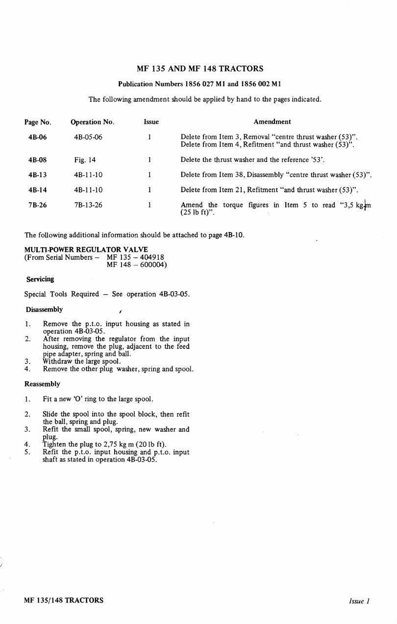
ecomanual.me MF 135 AND MF 148 TRACTORS Publication Numbers 1856 027 Ml and 1856 002 Ml The following amendment should be applied by hand to the pages indicated. Page No. Operation No. 4B-06 4B-14 7B-26 4B-05-06 Fig. 14 4B-11-10 4B-1 1-10 7B- 13-26 Amendment Delete from Item 3, Removal "centre thrust washer (53)". Delete from Item 4, Refitment "and thrust washer (53)". Delete the thrust washer and the reference '53'. Delete from Item 38, Disassembly "centre thrust washer (53)". Delete from Item 21, Refitment "and thrust washer (53)". Amend the torque figures in Item 5 to read "3,5 kgjm (25 lb ft)". r The following additional information should be attached to page 4B-10. MULTI-POWER REGULATOR VALVE (From Serial Numbers — MF 135 — 404918 MF 148 - 600004) Servicing Special Tools Required — See operation 4B-03-05. Disassembly , 1. Remove the p.t.o. input housing as stated in operation 4B-03-05. 2. After removing the regulator from the input housing, remove the plug, adjacent to the feed pipe adapter, spring and ball. 3. Withdraw the large spool. 4. Remove the other plug washer, spring and spool. Reassembly 1 . Fit a new 'O' ring to the large spool. 2. Slide the spool into the spool block, then refit the ball, spring and plug. 3. Refit the small spool, spring, new washer and plug. 4. Tighten the plug to 2,75 kg m (20 lb ft). 5. Refit the p.t.o. input housing and p.t.o. input shaft as stated in operation 4B-03-05. MF 135/148 TRACTORS Issue 1 www.EcoManual.me
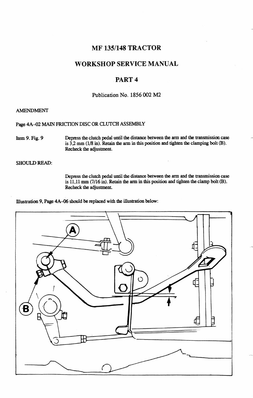
ecomanual.me MF 135/148 TRACTOR WORKSHOP SERVICE MANUAL PART 4 Publication No. 1856 002 M2 AMENDMENT Page 4A-02 MAINFRICTIONDISC OR CLUTCHASSEMBLY Item 9. Fig. 9 Depress the clutch pedal until the distance between die arm and the transmission case is 32 mm (1/8 in). Retain the arm in this position and tighten the clamping bolt (B). Recheck the adjustment. SHOULD READ: Depress the clutch pedal until the distance between the aim and the transmission case is 11.11mm (7/16 in). Retain the aim inthis position and tighten the clamp bolt (B). Recheck the adjustment. Illustration 9, Page 4A-06 should be replaced with the illustration below: www.EcoManual.me
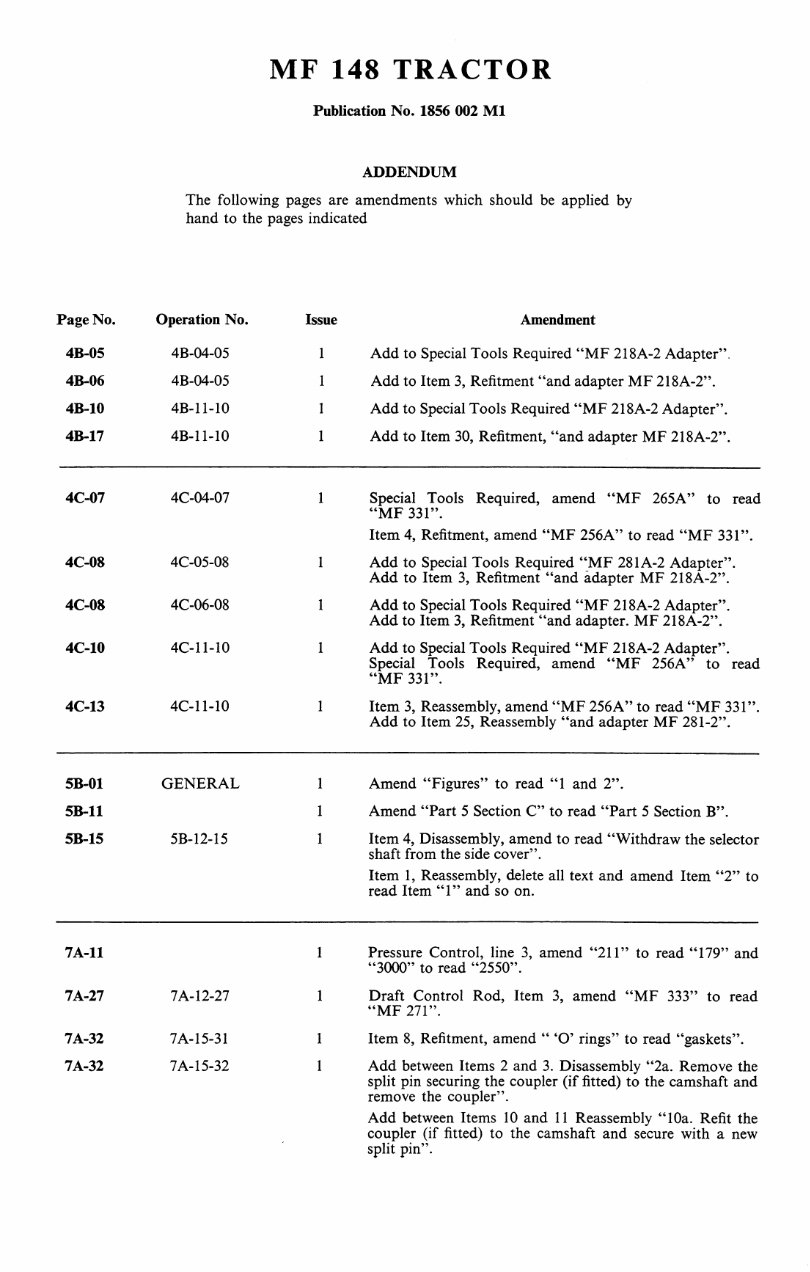
ecomanual.me MF 148 TRACTOR Publication No. 1856 002 Ml ADDENDUM The following pages are amendments which should be applied by hand to the pages indicated Page No. Operation No. Issue Amendment 4B-05 4B-04-05 1 Add to Special Tools Required "MF 218A-2 Adapter". 4B-06 4B-04-05 1 Add to Item 3, Refitment "and adapter MF 218A-2". 4B-10 4B-11-10 1 Add to Special Tools Required "MF 218A-2 Adapter". 4B-17 4B-11-10 1 Add to Item 30, Refitment, "and adapter MF 218A-2". 4C-07 4C-04-07 1 Special Tools Required, amend "MF 265A" to read "MF 331". Item 4, Refitment, amend "MF 256A" to read "MF 331". 4C-08 4C-05-08 1 Add to Special Tools Required "MF 281A-2 Adapter". Add to Item 3, Refitment "and adapter MF 218A-2". 4C-08 4C-06-08 1 Add to Special Tools Required "MF 218A-2 Adapter". Add to Item 3, Refitment "and adapter. MF 218A-2". 4C-10 4C-11-10 1 Add to Special Tools Required "MF 218A-2 Adapter". Special Tools Required, amend "MF 256A" to read "MF 331". 4C-13 4C-11-10 1 Item 3, Reassembly, amend "MF 256A" to read "MF 331". Add to Item 25, Reassembly "and adapter MF 281-2". 5B-01 GENERAL 1 Amend "Figures" to read "1 and 2". 5B-11 1 Amend "Part 5 Section C" to read "Part 5 Section B". 5B-15 5B-12-15 1 Item 4, Disassembly, amend to read "Withdraw the selector shaft from the side cover". Item 1, Reassembly, delete all text and amend Item "2" to read Item "1" and so on. 7A-11 1 Pressure Control, line 3, amend "211" to read "179" and "3000" to read "2550". 7A-27 7A-12-27 1 Draft Control Rod, Item 3, amend "MF 333" to read "MF 271". 7A-32 7A-15-31 1 Item 8, Refitment, amend " 'O' rings" to read "gaskets". 7A-32 7A- 15-32 1 Add between Items 2 and 3. Disassembly "2a. Remove the split pin securing the coupler (if fitted) to the camshaft and remove the coupler". Add between Items 10 and 11 Reassembly "10a. Refit the coupler (if fitted) to the camshaft and secure with a new split pin". www.EcoManual.me
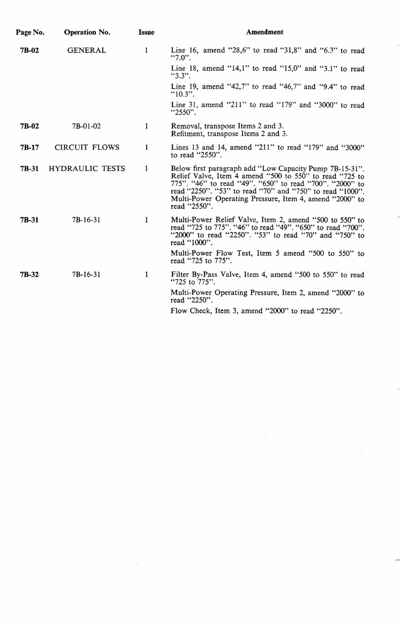
ecomanual.me Page No. Operation No. Issue Amendment 7B-02 GENERAL 1 Line 16, amend "28,6" to read "31,8" and "6.3" to read "7.0". Line 18, amend "14,1" to read "15,0" and "3.1" to read "3.3". Line 19, amend "42,7" to read "46,7" and "9.4" to read "10.3". Line 31, amend "211" to read "179" and "3000" to read "2550". 7B-02 7B-01-02 1 Removal, transpose Items 2 and 3. Refitment, transpose Items 2 and 3. 7B-17 CIRCUIT FLOWS 1 Lines 13 and 14, amend "211" to read "179" and "3000" to read "2550". 7B-31 HYDRAULIC TESTS 1 Below first paragraph add "Low Capacity Pump 7B-15-31". Relief Valve, Item 4 amend "500 to 550" to read "725 to 775". "46" to read "49". "650" to read "700". "2000" to read "2250". "53" to read "70" and "750" to read "1000". Multi-Power Operating Pressure, Item 4, amend "2000" to read "2550". 7B-31 7B- 16-31 1 Multi-Power Relief Valve, Item 2, amend "500 to 550" to read "725 to 775". "46" to read "49". "650" to read "700". "2000" to read "2250". "53" to read "70" and "750" to read "1000". Multi-Power Flow Test, Item 5 amend "500 to 550" to read "725 to 775". 7B-32 7B- 16-31 1 Filter By-Pass Valve, Item 4, amend "500 to 550" to read "725 to 775". Multi-Power Operating Pressure, Item 2, amend "2000" to read "2250". Flow Check, Item 3, amend "2000" to read "2250". www.EcoManual.me
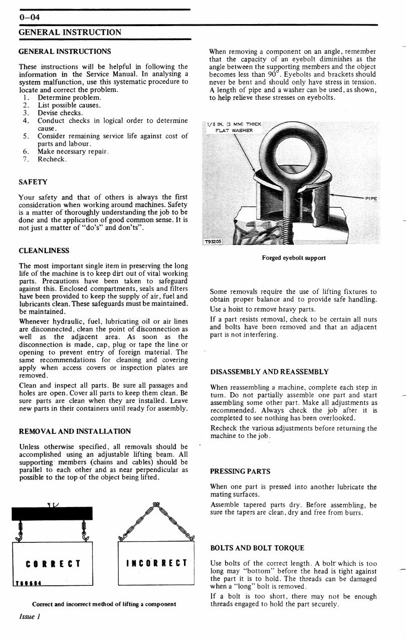
ecomanual.me 0-04 GENERAL INSTRUCTION GENERAL INSTRUCTIONS These instructions will be helpful in following the information in the Service Manual. In analysing a system malfunction, use this systematic procedure to locate and correct the problem. 1. Determine problem. 2. List possible causes. 3. Devise checks. 4. Conduct checks in logical order to determine cause . 5. Consider remaining service life against cost of parts and labour. 6. Make necessary repair. 7. Recheck. SAFETY Your safety and that of others is always the first consideration when working around machines. Safety is a matter of thoroughly understanding the job to be done and the application of good common sense. It is not just a matter of "do's" and don'ts". CLEANLINESS The most important single item in preserving the long life of the machine is to keep dirt out of vital working parts. Precautions have been taken to safeguard against this. Enclosed compartments, seals and filters have been provided to keep the supply of air, fuel and lubricants clean. These safeguards must be maintained. be maintained. Whenever hydraulic, fuel, lubricating oil or air lines are disconnected, clean the point of disconnection as well as the adjacent area. As soon as the disconnection is made, cap, plug or tape the line or opening to prevent entry of foreign material. The same recommendations for cleaning and covering apply when access covers or inspection plates are removed. Clean and inspect all parts. Be sure all passages and holes are open. Cover all parts to keep them clean. Be sure parts are clean when they are installed. Leave new parts in their containers until ready for assembly. REMOVAL AND INSTALLATION Unless otherwise specified, all removals should be accomplished using an adjustable lifting beam. All supporting members (chains and cables) should be parallel to each other and as near perpendicular as possible to the top of the object being lifted. When removing a component on an angle, remember that the capacity of an eyebolt diminishes as the angle between the supporting members and the object becomes less than 90 . Eyebolts and brackets should never be bent and should only have stress in tension. A length of pipe and a washer can be used, as shown, to help relieve these stresses on eyebolts. ;/3 IK. (3 MM) THICK FLAT WASHER Forged eyebolt support Some removals require the use of lifting fixtures to obtain proper balance and to provide safe handling. Use a hoist to remove heavy parts. If a part resists removal, check to be certain all nuts and bolts have been removed and that an adjacent part is not interfering. DISASSEMBLY AND REASSEMBLY When reassembling a machine, complete each step in turn. Do not partially assemble one part and start assembling some other part. Make all adjustments as recommended. Always check the job after it is completed to see nothing has been overlooked. Recheck the various adjustments before returning the machine to the job . PRESSING PARTS When one part is pressed into another lubricate the mating surfaces. Assemble tapered parts dry. Before assembling, be sure the tapers are clean, dry and free from burrs. CORRECT INCORRECT Correct and incorrect method of lifting a component BOLTS AND BOLT TORQUE Use bolts of the correct length. A bolt" which is too long may "bottom" before the head is tight against the part it is to hold. The threads can be damaged when a "long" bolt is removed. If a bolt is too short, there may not be enough threads engaged to hold the part securely. Issue 1 www.EcoManual.me
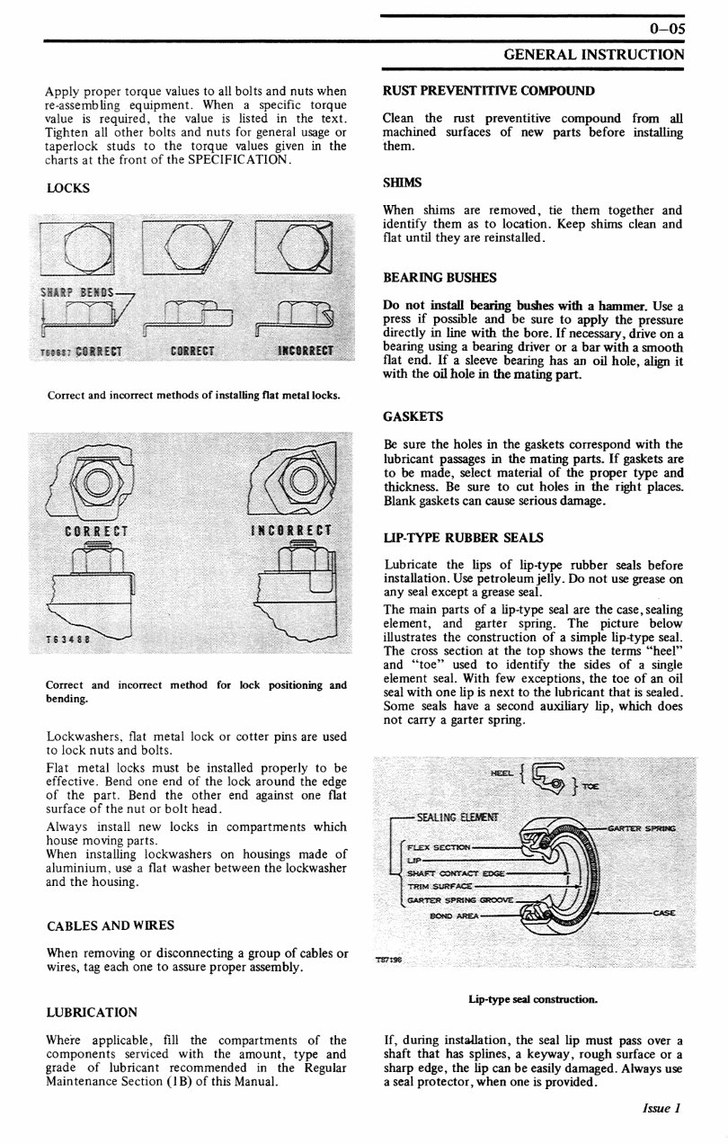
ecomanual.me 0-05 GENERAL INSTRUCTION Apply proper torque values to all bolts and nuts when re-assembling equipment. When a specific torque value is required, the value is listed in the text. Tighten all other bolts and nuts for general usage or taperlock studs to the torque values given in the charts at the front of the SPECIFICATION. LOCKS mm? ieiss — j j r tmm; PB1I8T COSiECT 1KIMECT Correct and incorrect methods of installing flat metal locks. CORRECT IKC8SRCI Correct and incorrect method for lock positioning and bending. Lockwashers, flat metal lock or cotter pins are used to lock nuts and bolts. Flat metal locks must be installed properly to be effective. Bend one end of the lock around the edge of the part. Bend the other end against one flat surface of the nut or bolt head. Always install new locks in compartments which house moving parts. When installing lockwashers on housings made of aluminium, use a flat washer between the lockwasher and the housing. CABLES AND WIRES When removing or disconnecting a group of cables or wires, tag each one to assure proper assembly. RUST PREVENTITIVE COMPOUND Clean the rust preventitive compound from all machined surfaces of new parts before installing them. SHIMS When shims are removed, tie them together and identify them as to location. Keep shims clean and flat until they are reinstalled. BEARING BUSHES Do not install bearing bushes with a hammer. Use a press if possible and be sure to apply the pressure directly in line with the bore. If necessary, drive on a bearing using a bearing driver or a bar with a smooth flat end. If a sleeve bearing has an oil hole, align it with the oil hole in the mating part. GASKETS Be sure the holes in the gaskets correspond with the lubricant passages in the mating parts. If gaskets are to be made, select material of the proper type and thickness. Be sure to cut holes in the right places. Blank gaskets can cause serious damage. UP-TYPE RUBBER SEALS Lubricate the lips of lip-type rubber seals before installation. Use petroleumjelly. Do not use grease on any seal except a grease seal. The main parts of a lip-type seal are the case, sealing element, and garter spring. The picture below illustrates the construction of a simple lip-type seal. The cross section at the top shows the terms "heel" and "toe" used to identify the sides of a single element seal. With few exceptions, the toe of an oil seal with one lip is next to the lubricant that is sealed. Some seals have a second auxiliary lip, which does not carry a garter spring. SEALING FLEX SECTION - SHAFT CONTACT EOQs> TRW SURFACE CARTER SPRANG GROOVE . -CARTER SF&m* LUBRICATION Lip-type seal construction. Where applicable, fill the compartments of the components serviced with the amount, type and grade of lubricant recommended in the Regular Maintenance Section (IB) of this Manual. If, during installation, the seal lip must pass over a shaft that has splines, a keyway, rough surface or a sharp edge, the lip can be easily damaged. Always use a seal protector, when one is provided. Issue 1 www.EcoManual.me
The repair service manual for the Massey Ferguson MF135 MF135 Tractor is designed for instant access and is primarily intended for professional technicians. However, it also provides sufficient information for do-it-yourself mechanics and individuals performing repairs and maintenance on the Massey Ferguson MF135 MF135 Tractor.
This manual caters to individuals with basic knowledge in electrical and mechanical concepts. It serves as a valuable reference for maintaining and repairing the vehicle or engine, covering topics typically found in a factory service manual and owner's manual for the Massey Ferguson MF135 MF135 Tractor.
It offers guidance on fundamental repair and maintenance procedures, providing step-by-step instructions to empower owners to make informed decisions about maintaining and repairing their Massey Ferguson MF135 MF135 Tractor.
Product Details:
File Format: .PDF
Language: English
Specifications: Full Printable
Zoom IN/OUT: YES
Delivery: Instant
Requirements: Adobe Reader & Win
Compatible: All Versions of Windows & Mac
There is no significant difference between a paper manual and the digital manual for the Massey Ferguson MF135 MF135 Tractor. Both versions include step-by-step repair procedures, critical specifications, illustrations, maintenance, disassembly, assembly, cleaning and reinstalling procedures, and more. The advantage of the digital manual is the ability to access it instantly and address issues promptly.
Example of Covered Information:
Engine Removal
Wiring Diagrams
General Information
Specifications
Lube Points
Oil Types
Periodic Maintenance and Tune-Up Procedures
Engine Servicing
Disassembly and Reassembly
Fuel and Lubrication Systems
Electrical System
Chassis, Steering, and Suspension
Brakes and Wheels
Charging and Starter Systems
Battery and Switches
Service Data and Tools
Tightening Torques
Complete Engine and Fuel System Service
Factory Repair Procedures
Exhaust and Cooling System Service
Fault Finding and Clutch Removal
Transmission and Gearbox Service
Bodywork and Electrics
Maintenance Schedules and Detailed Specifications
Plus More
The Massey Ferguson MF135 MF135 Tractor repair service manual is a comprehensive resource for both professional mechanics and DIY enthusiasts.
Recently Viewed
5,521,897Happy Clients
2,594,462eManuals
1,120,453Trusted Sellers
15Years in Business
Price:
Actual Price:
Massey Ferguson MF135 MF148 Tractor Service & Repair Manual