

Massey Ferguson MF135 Tractor Operator's Manual
What's Included?
Fast Download Speeds
Online & Offline Access
Access PDF Contents & Bookmarks
Full Search Facility
Print one or all pages of your manual
--
Operator's Manual
MF 135 TRACTOR
F=' Massey Ferguson
Downloaded from www.Manualslib.com manuals search engine
Massey Ferguson
TO OUR CUSTOMER:
Congratulations on your selection of a Massey-Ferguson Product. We
believe you have exercised excellent judgment in the purchase of your
Massey-Ferguson machine. We are most appreciative of your patronage.
Your Dealer has performed every pre-delivery service on your new ma-
chine. This machine is covered by a Registration and Inspection Certifi-
cate which is printed on the inside back cover.
He will be happy to acquaint you with the operating and maintenance
instructions given in this manual, and to instruct you in the proper and
varied applications of this machine. Call on him at any time when you
have a question, or need equipment related to the use of your machine.
We recommend that you carefully read this entire manual before oper-
ating the unit. Also, time spent in becoming fully acquainted with its per-
formance features, adjustments and maintenance schedules will be repaid
in a long and satisfactory life of the product.
This piece of equipment is covered by warranty. The warranty agree-
ment is printed in the back of this manual.
Massey-Ferguson reserves the right to make changes or add improvements to its products at any time
without incurring any obligation to make such changes to products manufactured previously. Massey-
Ferguson, or its dealers, accept no responsibility for variations which may be evident in the actual speci-
fications of its products and the statements and descriptions contained in this publication.
Massey-Ferguson Inc.
1901 BELL AVENUE, DES MOINES, IOWA 50315
Massey-Ferguson Industries Limited
915 Kl NG STREET WEST, TORONTO, CANADA
Downloaded from www.Manualslib.com manuals search engine
A
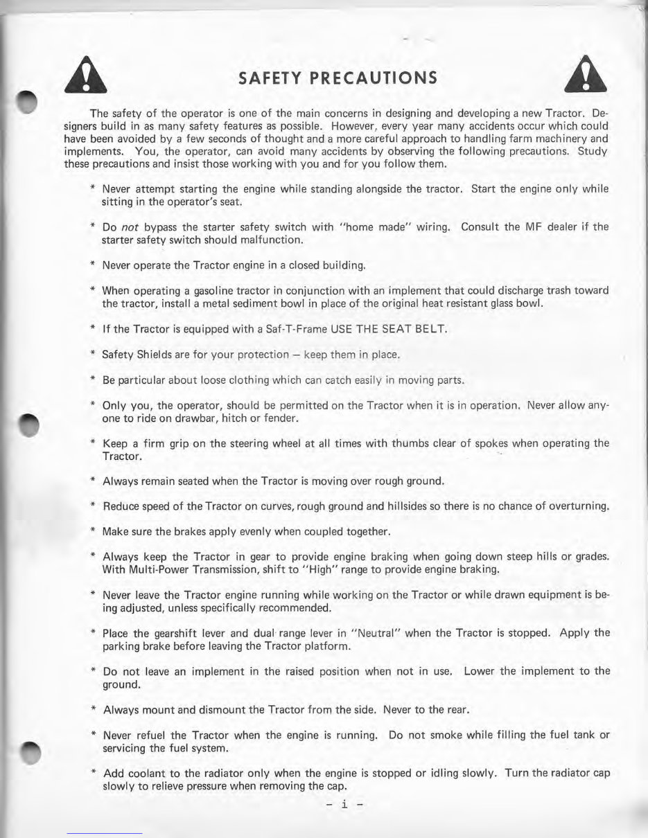
SAFETY PRECAUTIONS
A
The safety of the operator is one of the main concerns in designing and developing a new Tractor. De-
signers build in as many safety features as possible. However, every year many accidents occur which could
have been avoided by a few seconds of thought and a more careful approach to handling farm machinery and
implements. You, the operator, can avoid many accidents by observing the following precautions. Study
these precautions and insist those working with you and for you follow them.
* Never attempt starting the engine while standing alongside the tractor. Start the engine only while
sitting in the operator's seat.
* Do not bypass the starter safety switch with "home made" wiring. Consult the MF dealer if the
starter safety switch should malfunction.
* Never operate the Tractor engine in a closed building.
* When operating a gasoline tractor in conjunction with an implement that could discharge trash toward
the tractor, install a metal sediment bowl in place of the original heat resistant glass bowl.
* If the Tractor is equipped with a Saf-T-Frame USE THE SEAT BELT.
* Safety Shields are for your protection - keep them in place.
* Be particular about loose clothing which can catch easily in moving parts.
* Only you, the operator, should be permitted on the Tractor when it is in operation. Never allow any-
one to ride on drawbar, hitch or fender.
* Keep a firm grip on the steering wheel at all times with thumbs clear of spokes when operating the
Tractor.
* Always remain seated when the Tractor is moving over rough ground.
* Reduce speed of the Tractor on curves, rough ground and hillsides so there is no chance of overturning.
* Make sure the brakes apply evenly when coupled together.
* Always keep the Tractor in gear to provide engine braking when going down steep hills or grades.
With Multi-Power Transmission, shift to "High" range to provide engine braking.
* Never leave the Tractor engine running while working on the Tractor or while drawn equipment is be-
ing adjusted, unless specifically recommended.
* Place the gearshift lever and dual range lever in "Neutral" when the Tractor is stopped. Apply the
parking brake before leaving the Tractor platform.
* Do not leave an implement in the raised position when not in use. Lower the implement to the
ground.
* Always mount and dismount the Tractor from the side. Never to the rear.
* Never refuel the Tractor when the engine is running. Do not smoke while filling the fuel tank or
servicing the fuel system.
* Add coolant to the radiator only when the engine is stopped or idling slowly. Turn the radiator cap
slowly to relieve pressure when removing the cap.
- i -
Downloaded from www.Manualslib.com manuals search engine
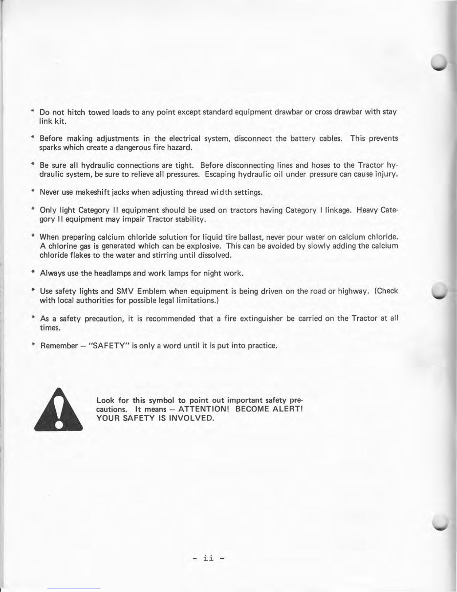
* Do not hitch towed loads to any point except standard equipment drawbar or cross drawbar with stay
link kit. ·
* Before making adjustments in the electrical system, disconnect the battery cables. This prevents
sparks which create a dangerous fire hazard.
* Be sure all hydraulic connections are tight. Before disconnecting lines and hoses to the Tractor hy-
draulic system, be sure to relieve all pressures. Escaping hydraulic oil under pressure can cause injury.
* Never use makeshift jacks when adjusting thread width settings.
* Only light Category 11 equipment should be used on tractors having Category I linkage. Heavy Cate-
gory 11 equipment may impair Tractor stability.
* When preparing calcium chloride solution for liquid tire ballast, never pour water on calcium chloride.
A chlorine gas is generated which can be explosive. This can be avoided by slowly adding the calcium
chloride flakes to the water and stirring until dissolved.
* Always use the headlamps and work lamps for night work.
* Use safety lights and SMV Emblem when equipment is being driven on the road or highway. (Check
with local authorities for possible legal limitations.)
* As a safety precaution, it is recommended that a fire extinguisher be carried on the Tractor at all
times.
* Remember - "SAFETY" is only a word until it is put into practice.
Look for this symbol to point out important safety pre-
cautions. It means - ATTENTION! BECOME ALERT!
YOUR SAFETY IS INVOLVED.
- ii -
Downloaded from www.Manualslib.com manuals search engine
IMPORTANT DIESEL FUEL PRECAUTIONS
THE FUEL INJECTION EQUIPMENT IS DESIGNED FOR EFFICIENCY, DURABILITY AND
LONG LIFE. HOWEVE'R, IT CAN BE SERIOUSLY DAMAGED BY WATER, SEDIMENT OR IN-
CORRECT FUEL. THE EXTENT OF TROUBLE-FREE OPERATION AND THE ACTUAL LIFE
OF THE COMPONENTS WILL DEPEND ON THE CARE GIVEN THE SYSTEM.
READ THE INFORMATION LISTED ON THIS PAGE THOROUGHLY AND ADOPT THE
RECOMMENDED PRACTICES. ADHERENCE TO THESE PRACTICES WILL ASSURE ECO-
NOMICAL, TROUBLE-FREE OPERATION AND SATISFACTION WITH YOUR DIESEL
TRACTOR.
1. Select a REPUTABLE SUPPLIER and buy only CLEAN diesel fuel which meets the RE-
QUIRED SPECIFICATIONS.
2. Keep fuel clean by adhering to the following practices:
a. Store fuel in tanks equipped with a WATER TRAP. DRAIN TRAPS REGULARLY.
Do not store diesel fuel in galvanized tanks.
b. If it is necessary to store the fuel in drums, make sure they are free of WATER,
GASOLINE AND SEDIMENT. Keep drums under cover, away from direct sunlight
and rain. Keep plugs in place and tight.
c. Once in place, avoid moving the tank or drum.
d. Do not use the last few gallons of fuel from the storage tank, as it is likely to con-
tain water and sediment.
e. Handle the fuel as little as possible. AVOID USING CANS AND FUNNELS TO
TRANSFER FUEL, AS THEY ARE DIFFICULT TO KEEP CLEAN.
3. Fill Tractor fuel tank at the end of each day's operation to prevent condensation.
4. Inspect the agglomerator bowl DAILY, before starting the engine. Drain and clean
bowl, if water or sediment is present.
IMPORTANT: IF THE AG G L 0 MER AT 0 R BOWL REQUIRES FREQUENT DRAINING,
ADOPT BETTER METHODS OF STORING AND TRANSFERRING THE FUEL. WATER
OR SEDIMENT WILL DAMAGE THE HIGHLY PRECISION INJECTION PUMP AND IN-
JECTORS.
5. Replace the primary fuel filter and secondary filter at the recommended hourly inter-
vals. DIRTY FUEL FILTERS WILL REDUCE POWER. Make sure to CAREFULLY CLEAN
the outside of the filter before removing. USE ONLY GENUINE MF FILTER ELEMENTS.
6. If the injection pump, injectors, or the fuel system should require adjustment or serv-
icing, CALL YOUR MASSEY-FERGUSON DEALER. He has the special training and tools re-
quired to do the job properly.
- iii -
Downloaded from www.Manualslib.com manuals search engine
INTRODUCTION
The information in this Manual describes the operation, maintenance and servicing of your
new Tractor to help you keep "on-the-go". The money you have invested in your Tractor will
be better spent if you take the time to READ this Manual and get to KNOW it. Every piece
of machinery feels better, works better and becomes more efficient when you are familiar with
it.
DO NOT neglect the maintenance that is recommended.
A machine which is properly maintained pays a bigger dividend than one which is neglected.
The maintenance and servicing described in this Manual can all be done with tools ordinarily
available.
Massey-Ferguson has engineered and tested these Tractors under all kinds of conditions to
produce a superior machine. They have kept it as simple as possible, so you can do many
small jobs. This Manual will help you, the operator, get the most out of your MF Tractor.
The reference to left-hand and right-hand used throughout the Manual refers to the position
when seated in the operator's seat, facing forward.
TRACTOR IDENTIFICATION
For prompt, efficient service when ordering parts or requesting repairs at your local MF
Dealer, record the complete Serial Numbers in spaces provided.
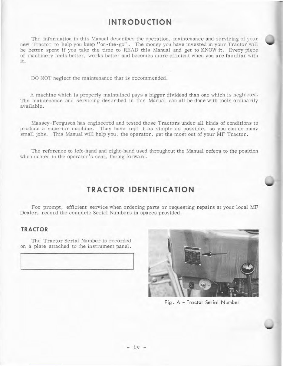
TRACTOR
The Tractor Serial Number is recorded
on a plate attached to the instrument panel.
- iv -
Fig. A - Tractor Serial Number
Downloaded from www.Manualslib.com manuals search engine
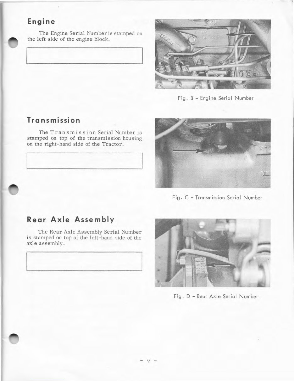
Engine
The Engine Serial Number is stamped on
the left side of the engine block.
Transmission
The Tran s mi s s ion Serial Number is
stamped on top of the transmission housing
on the right-hand side of the Tractor.
Rear Axle Assembly
The Rear Axle Assembly Serial Number
is stamped on top of the left-hand side of the
axle assembly.
- v -
Fig. B - Engine Serial Number
Fig. C - Transmission Serial Number
Fig. D - Rear Axle Serial Number
Downloaded from www.Manualslib.com manuals search engine
CONTROLS AND INSTRUMENTS
Controls ...................... .
Instruments ................... .
OPERATION
INDEX
Page
l
l
5
7
Page
Auxiliary Hydraulics System 18
Lock-Out and Variable Drop
Cartridge (Accessory) . . . . • • 19
Attaching and Detaching Imple-
Pre-Starting Inspection . . . . . • • . . 7
ments . . . . . . . . . . . . . . . . ... . . . . . 19
Crankcase Oil Level ..••..•..
Transmission and Hydraulic
Oil Level .•..• ...... • ......
Radiator Coolant Level .• ......
Fuel Level ................. .
Fuel System ...... •..• .......
Starting the Engine ............ .
Warm Weather Starting ...... .
Cold Weather Starting ....... •
Tractor Warm-Up Period ..... .
Observing the Instruments .... .
Operating the Tractor ..... • ....
Break-In Procedure .......... .
Selecting Ground Speeds ...... .
Speed Chart ...... • ...........
Shifting Gears .............. •
Stopping the Tractor .... •.•...
Towing the Tractor ........ •..
Multi-Power Transmission
Test for Overload ........... •
Hydraulic System ..• ...........
When to Use Draft Control
Using Draft Control ...• ......
When to Use Response Control ..
Using Response Control ...... .
Inner Quadrant Control Lever ..
When to Use Position Control .. .
Using Position Control ....... .
When to Use Pressure Control
(Optional) .•..• .............
Using Pressure Control
(Optional) ................. .
Using Pressure Control with
Pull-Type Implements <pnly) ••
Constant Pumping Range ...... •
7
7
7
7
8
9
9
10
11
11
11
11
12
13
14
14
14
14
15
15
16
16
16
16
17
17
17
Attaching 3-Point Hitch Imple-
ments . . . . . . . . . . . • . . . . . . . • . 19
Detaching 3-Point Hitch Imple-
ments . . . . . . . . . . . . . . . . . . . . . 20
Attaching and Detaching Pull-Type
Pressure Control Implements 20
Universal Pressure Control
Hitch (Accessory) . . . . . . . . . . 21
Swinging Drawbar .............. •
Adjustable Top Link ...... • .... •
Power Take-Off ................ .
''Live'' PTO ................ .
"Independent'' PTO .......... •
Transmission Speed PTO .... •..
OPERATING ADJUSTMENTS ..... . . .
Wheels and Tires .............. .
Front Wheel Tread Widths ....... .
Rear Wheel Tread Widths ........ .
Tire Pressures .................. .
Seat ..........................
Foam Float Seat ....... •..•...
Float-0-Matic Seat ..• .... •...
Pan Type Seat ..• ....... • .....
Liquid-Filling the Tires
22
22
23
23
24
24
25
25
25
26
27
28
28
29
29
30
17 FUEL AND FUEL CARE
31
17
18
18
- vi -
Fuels
.........................
Gasoline Engine
Diesel Engine .............. .
31
31
31
Downloaded from www.Manualslib.com manuals search engine
Fuel Care
LUBRICANTS AND LUBRICATION ..
General Information ........... .
Storing Lubricants ............ .
Lubrication Symbols ........... .
Lubricants ........... , ..... •••
Lubricants and Capacities
MAINTENANCE AND SERVICING ...
Maintenance
Each 10-Hour or Daily Mainte-
nance Chart ............... .
Daily for First 14 Days Oper-
ation Maint e nance Chart ..•..
Each 50 Ho urs or Break-In
Maintenance Chart ......... .
Each 100 Hours Maintenance
Chart ................. •...
Each 200 Hours Maintenance
INDEX (Continued)
Page
31
32
32
32
32
32
33
35
35
35
36
36
37
Gasoline Fuel System .. , •.••..
Ignition System (Gasoline) .•..•
Air Filter .......... •...• ....
Electrical System ..•...••...•.
Fan Belt .................... .
Cooling System .......... •.•.
Clutch Adjustment ...••.•.•...
Differential Lock (Optional) ....
Brake Adjustment ......... •..
Front Wheel Alignment .••...•.
Repacking Front Wheel Bearings.
Hydraulic Control Quadrant
Adjustment ..•..• ..........
Throttle Control Lever
Adjustment ..... •...• ..... •
Rear Wheels ..• .... , •• ...... •
Power Steering ..• ......... •..
Engine Cylinder Head ....... .
Valve Tappets .... •...••..•..
Engine Crankcase Oil ...•..•..
Transmission, Differential and
Hydraulic System ...•...•...
Page
40
40
42
45
46
47
48
49
50
50
51
52
52
52
52
53
53
53
53
Chart . . . . . . . . . . . . . . . . . . . . . 37
Each 500 Hours Maintenance
Chart ................. ••..
Each 750 .Hours (or Annually)
Maintenance Chart ......... •
Servicing ..... • ................
Diesel Fuel System .......... .
37
38
38
38
TRACTOR STORAGE . . . . . • . . • . . . • . 55
REMOVING TRACTOR FROM
STORAGE • • • . • . . • . . . . • • . . . . . . • 56
TROUBLE-SHOOTING . . . • • . . . . • • . 57
ACCESSORIES . . . . . . . . . . • . . . • • . . . 61
SPECIFICATIONS ............ , • . . . 63
- vii -
Downloaded from www.Manualslib.com manuals search engine
CONTROLS AND INSTRUMENTS
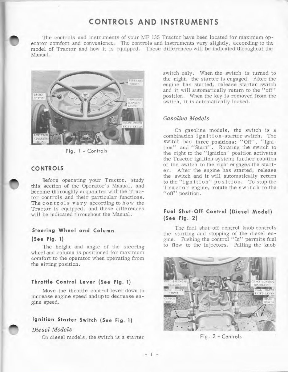
The controls and instruments of your MF 135 Tractor have been located for maximum op-
erator comfort and convenience. The controls and instruments vary slightly, according to the
model of Tractor and how it is equipped. These differences will be indicated throughout the
Manual.
Fig. l - Controls
CONTROLS
Before operating your Tractor, study
this section of the Operator's Manual, and
become thoroughly acquainted with the Trac-
tor controls and their particular functions.
The controls vary according to how the
Tractor is equipped, and these differences
will be indicated throughout the Manual.
Steering Wheel and Column
(See Fig. 1)
The height and angle of the steering
wheel and column is positioned for maximum
comfort to the operator when operating from
the sitting position.
Throttle Control Lever (See Fig. 1)
Move the throttle control lever down to
increase engine speed and up to decrease en-
gine speed.
Ignition Starter Switch (See Fig. 1)
Diesel Models
On diesel models, the switch is a starter
- 1 -
switch only. When the switch is turned to
the right, the starter is engaged. After the
engine has started, release starter switch
and it will automatically return to the "off"
position. When the key is removed from the
switch, it is automatically locked.
Gasoline Models
On gasoline models, the switch is a
combination ignition-starter switch. The
switch has three positions: "Off", "Igni-
tion" and "Start". Rotating the switch to
the right to the "ignition" position activates
the Tractor ignition system; further rotation
of the switch to the right engages the start-
er. After the engine has started, release
the switch and it will automatically return
to the '' i g n it i on' ' po s i t i on. To stop the
Tractor engine, rotate the switch to the
"off" position.
Fuel Shut-Off Control (Diesel Model)
(See Fig. 2)
The fuel shut-off control knob controls
the starting and stopping of the diesel en -
gine. Pushing the control "In" permits fuel
to flow to the injectors. Pulling the knob
Fig. 2 - Controls
Downloaded from www.Manualslib.com manuals search engine
You're Reading a Preview
What's Included?
Fast Download Speeds
Online & Offline Access
Access PDF Contents & Bookmarks
Full Search Facility
Print one or all pages of your manual
$36.99
Viewed 87 Times Today


Secure transaction
What's Included?
Fast Download Speeds
Online & Offline Access
Access PDF Contents & Bookmarks
Full Search Facility
Print one or all pages of your manual
$36.99
Get your hands on the comprehensive Massey Ferguson 135 Tractor Operator's Instruction Book. This manual, available in PDF format, contains 145 pages of essential information for both professional mechanics and DIY enthusiasts. Whether you're looking to perform routine maintenance or tackle more complex repairs, this manual provides the detailed guidance you need to keep your Massey Ferguson 135 running smoothly.


