

Massey Ferguson 1010 & 1020 Tractor Service & Repair Manual
What's Included?
Fast Download Speeds
Online & Offline Access
Access PDF Contents & Bookmarks
Full Search Facility
Print one or all pages of your manual
SHOP MANUAL
MASSEY-FERGUSON
MODELS 1010 AND 1020
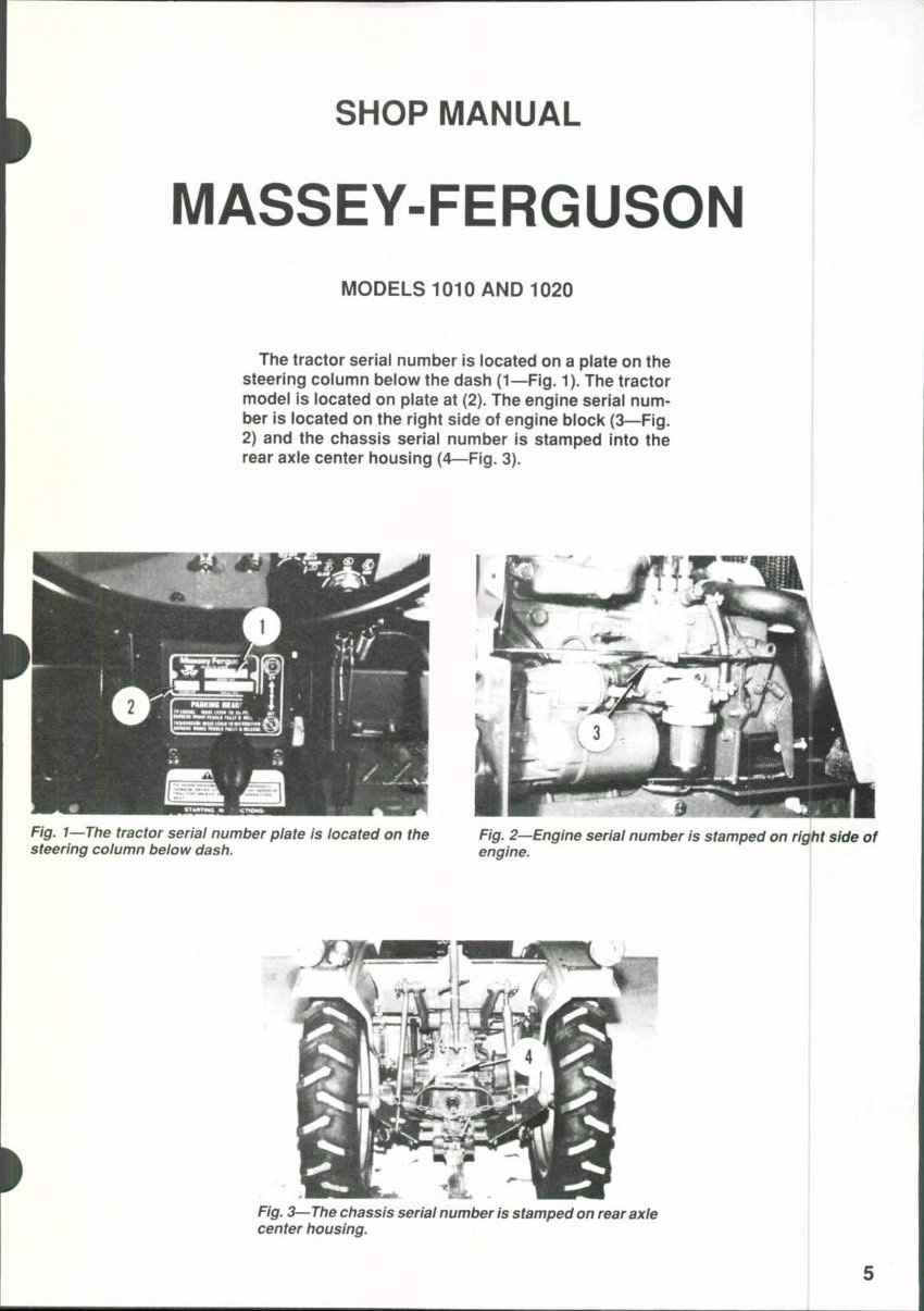
The tractor serial number is located on a plate on the
steering column below the dash (1—Fig. 1). The tractor
model is located on plate at (2). The engine serial num-
ber is located on the right side of engine block (3—Fig,
2) and the chassis serial number is stamped into the
rear axle center housing (4—Fig. 3).
Fig, I—The tractor serial number plate Is located on the Fig. 2—Englne serial number Is stamped on right side of
steering column below dash. engine.
Fig. 3—The chassis serial number Is stamped on rear axle
center housing.
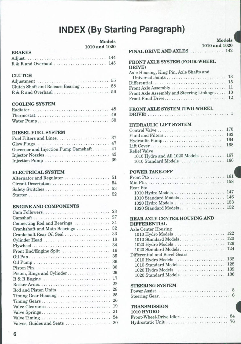
INDEX (By Starting Paragraph)
Models
1010 and 1020
BRAKES
Adjust 144
R & R and Overhaul 145
CLUTCH
Adjustment 55
Clutch Shaft and Release Bearing 58
R & R and Overhaul 56
COOLING SYSTEM
Radiator 48
Thermostat 49
Water Pump 50
DIESEL FUEL SYSTEM
Fuel Filters and Lines 37
Glow Plugs 47
Governor and Injection Pump Camshaft . 41
Injector Nozzles 43
Injection Pump 39
ELECTRICAL SYSTEM
Alternator and Regulator 51
Circuit Description 54
Safety Switches 53
Starter 52
ENGINE AND COMPONENTS
Cam Followers 23
Camshaft 27
Connecting Rod and Bearings 31
Crankshaft and Main Bearings 32
Crankshaft Rear Oil Seal 33
Cylinder Head 18
Flywheel 34
Front End/Engine Split 16
Oil Pan 35
Oil Pump 36
Piston Pin 30
Piston, Rings and Cylinder 29
R & R Engine 17
Rocker Arms 22
Rod and Piston Units 28
Timing Gear Housing 25
Timing Gears 26
Valve Clearance 19
Valve Springs 21
Valve Timing 24
Valves, Guides and Seats 20
Models
1010 and 1020
FINALDRIVE AND AXLES 142
FRONT AXLE SYSTEM (FOUR-WHEEL
DRIVE)
Axle Housing, King Pin, Axle Shafts and
Universal Joints 13
Differential 15
Front Axle Assembly H
Front Axle Assembly and Steering Linkage 10
Front Final Drive 12
FRONT AXLE SYSTEM (TWO-WHEEL
DRIVE) 1
HYDRAULIC LIFT SYSTEM
Control Valve 170
Fluid and Filters 163
Hydraulic Pump 164
Lift Cover 168
Relief Valve
1010 Hydro and All 1020 Models 167
1010 Standard Models 166
POWER TAKE-OFF i
Front Pto 161^
MidPto 158
Rear Pto
1010 Hydro Models 147
1010 Standard Models 146
1020 Hydro Models 153
1020 Standard Models 152
REAR AXLE CENTER HOUSING AND
DIFFERENTIAL
Axle Center Housing
1010 Hydro Models 122
1010 Standard Models 120
1020 Hydro Models 126
1020 Standard Models 124
Differential and Bevel Gears
1010 Hydro Models 132
1010 Standard Models 128
1020 Hydro Models 139
1020 Standard Models 136
STEERING SYSTEM
Power Assist 8
Steering Gear 6
TRANSMISSION
1010 HYDRO
Front-Wheel-Drive Idler 84
Hydrostatic Unit 76
Models
1010 and 1020
TRANSMISSION
1010 HYDRO (Cont.)
Lubrication 69
Overhaul 78
Range Transmission 80
Spacer Housing Assembly 79
Tests and Adjustments 71
Troubleshooting 70
TRANSMISSION
1010 STANDARD
Inspection 59
Lubrication 60
Overhaul 62
Remove and Reinstall 61
TRANSMISSION
1020 HYDRO
Front-Drive Output Shaft 118
Models
1010 and 1020
TRANSMISSION
1020 HYDRO (Cont.)
Hydrostatic Unit 109
Lubrication 102
Overhaul , 111
Range Transmission 113
Spacer 112
Tests and Adjustments 104
Troubleshooting 103
TRANSMISSION
1020 STANDARD
Creeper (Mode) Transmission 97
Front-Wheel Drive 100
Inspection. 86
Lubrication 87
Main and Range Transmission 89
Shifter Cover 88
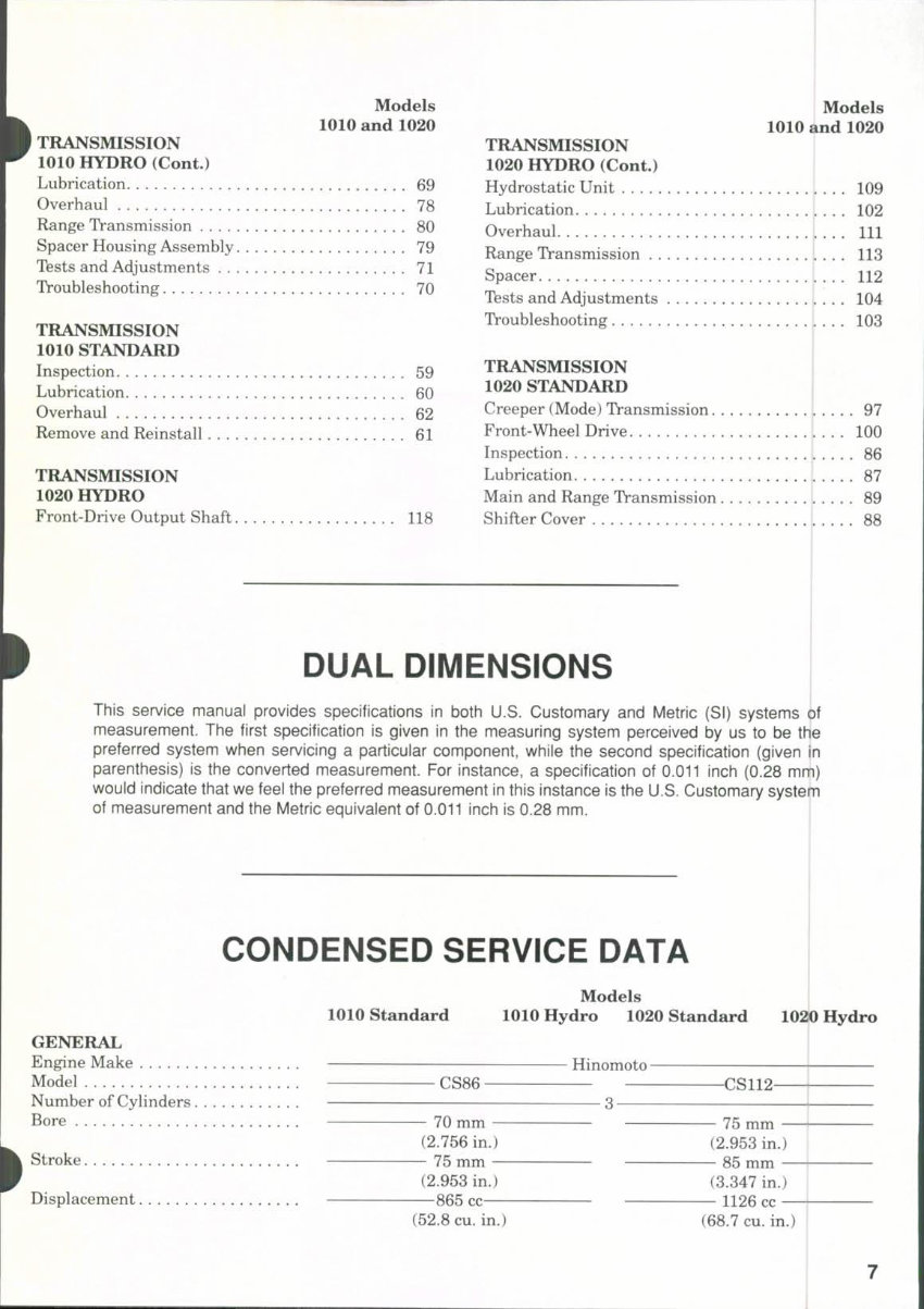
DUAL DIMENSIONS
This service manual provides specifications in both U.S. Customary and Metric (SI) systems of
measurement. The first specification is given in the measuring system perceived by us to be the
preferred system when servicing a particular component, while the second specification (given in
parenthesis) is the converted measurement. For instance, a specification of 0.011 inch (0.28 mm)
would indicate that we feel the preferred measurement in this instance is the U.S. Customary system
of measurement and the Metric equivalent of 0.011 inch is 0.28 mm.
CONDENSED SERVICE DATA
1010 standard
Models
1010 Hydro 1020 Standard 1020 Hydro
GENERAL
Engine Make
Model
Number of Cylinders.
Bore
Stroke
Displacement
Hinomoto -
CS86 • -CS112-
— 70 mm —
(2.756 in.)
— 75 mm —
(2.953 in.)
865 cc
(52.8 cu. in.)
— 75 mm —
(2.953 in.)
— 85 mm —
(3.347 in.)
— 1126 cc —
(68.7 cu. in.)
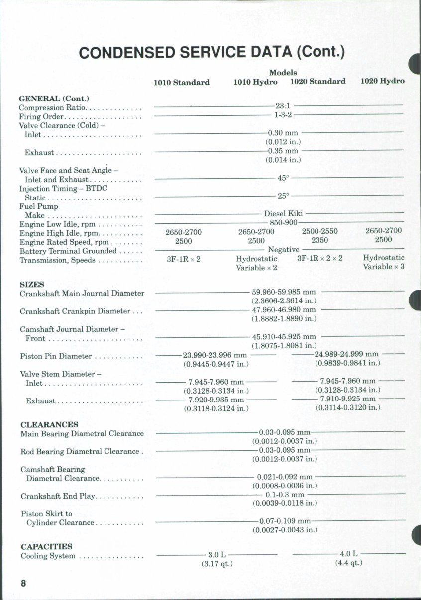
CONDENSED SERVICE DATA (Cont.)
Models
1010 Standard 1010 Hydro 1020 Standard 1020 Hydro
i
GENERAL (Cont.)
Compression Ratio " 23:1 —
Firing Order ~" 1-3-2 —
Valve Clearance (Cold) -
Inlet ' —0.30 mm ——
(0.012 in.)
Exhaust —0.35 mm
(0.014 in.)
Valve Face and Seat Angle -
Inlet and Exhaust ^ — 45°—
Injection Timing - BTDC
Static 25° -—
Fuel Pump
Make — Diesel Kiki —
Engine Low Idle, rpm ' 850-900 -
Engine High Idle, rpm 2650-2700 2650-2700 2500-2550 2650-2700
Engine Rated Speed, rpm 2500 2500 2350 2500
Battery Terminal Grounded Negative
Transmission, Speeds 3F-1R x 2 Hydrostatic 3F-1R x 2 x 2 Hydrostatic
Variable x 2 Variable x 3
SIZES
Crankshaft Main Journal Diameter • 59.960-59.985 mm
(2.3606-2.3614 in.)
Crankshaft Crankpin Diameter . . . 47.960-46.980 mm
(1.8882-1.8890 in.)
Camshaft Journal Diameter -
Front 45.910-45.925 mm
(1.8075-1.8081 in.)
Piston Pin Diameter 23.990-23.996 mm 24.989-24.999 mm
(0.9445-0.9447 in.) (0.9839-0.9841 in.)
Valve Stem Diameter -
Inlet 7.945-7.960 mm 7.945-7.960 mm
(0.3128-0.3134 in.) (0.3128-0.3134 in.)
Exhaust 7.920-9.935 mm 7.910-9.925 mm
(0.3118-0.3124 in.) (0.3114-0.3120 in.)
CLEARANCES
Main Bearing Diametral Clearance —^0.03-0,095 mm
(0.0012-0.0037 in.)
Rod Bearing Diametral Clearance . — 0.03-0.095 mm
(0.0012-0.0037 in.)
Camshaft Bearing
Diametral Clearance 0.021-0.092 mm
(0.0008-0.0036 in.)
Crankshaft End Play — 0.1-0.3 mm
(0.0039-0.0118 in.)
Piston Skirt to
Cylinder Clearance 0.07-0.109 mm
(0.0027-0.0043 in.)
CAPACITIES
Coohng System 3.0 L 4.0 L
(3.17 qt.) (4.4 qt.)
8
CONDENSED SERVICE DATA (Cont.)
Models
1010 Standard 1010 Hydro 1020 Standard 1020 Hydro
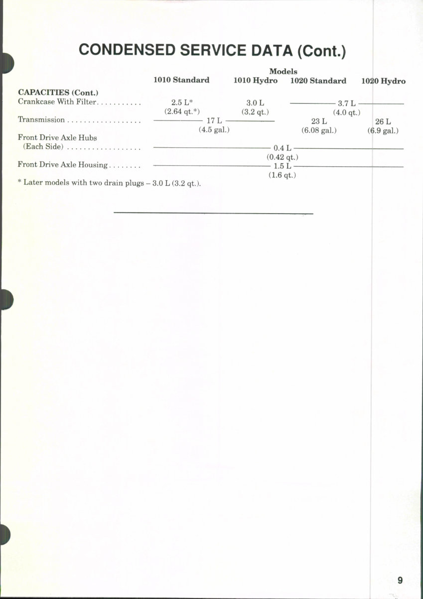
CAPACITIES (Cont.)
Crankcase With Filter 2.5 L* 3.0 L 3.7 L
(2.64 qt.*) (3.2 qt.) (4.0 qt.)
Transmission 17 L 23 L 26 L
(4.5 gal.) (6.08 gal.) (6.9 gal.)
Front Drive Axle Hubs
(Each Side) — 0.4 L
(0.42 qt.)
Front Drive Axle Housing 1,5 L
(1.6 qt.)
* Later models with two drain plugs - 3.0 L (3.2 qt.).
9
Paragraphs 1-3
MASSEY-FERGUSON
FRONT AXLE SYSTEM
(TWO-WHEEL DRIVE)
FRONT AXLE ASSEMBLY AND
STEERING LINKAGE
Two-Wheel-Drive Models
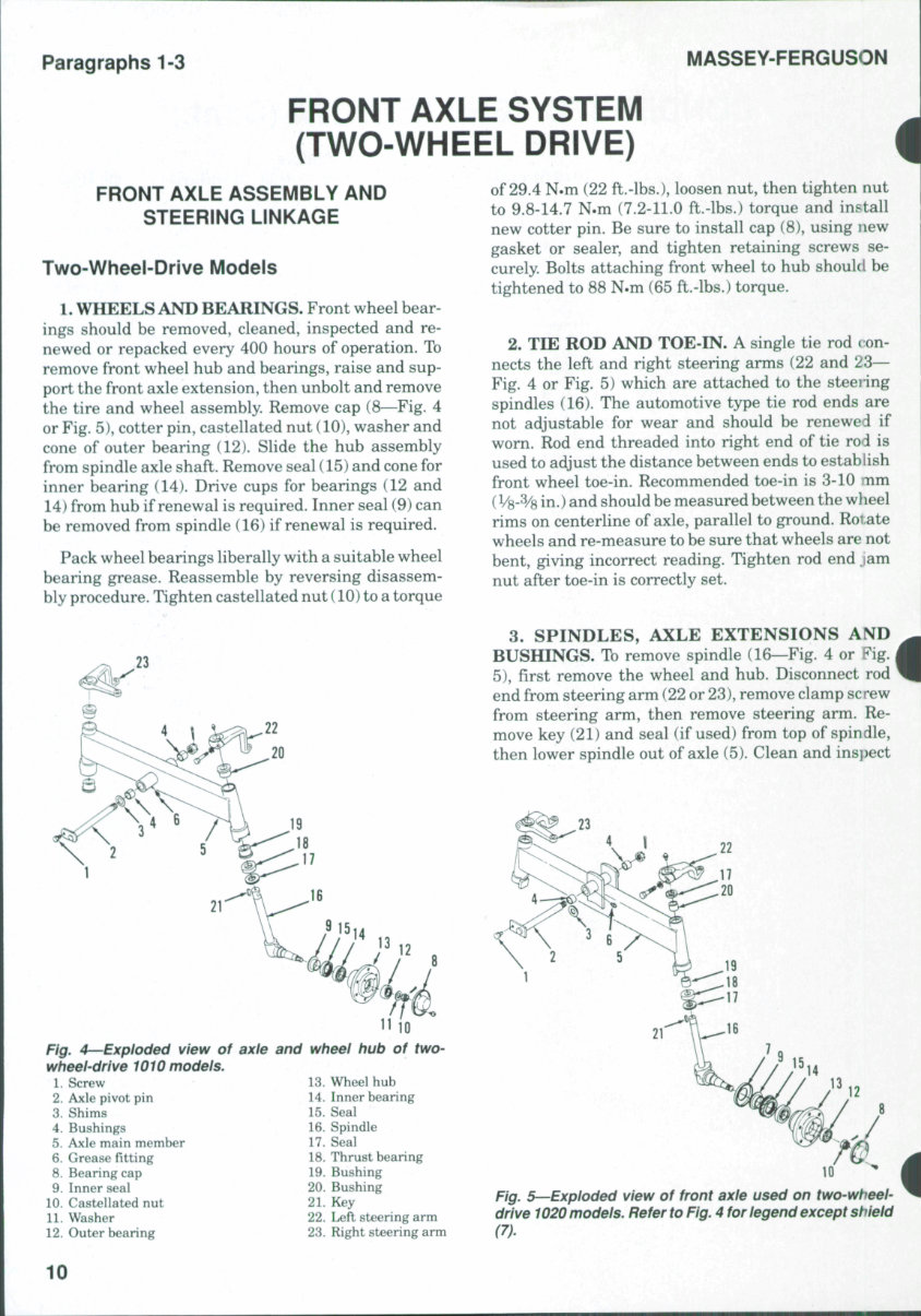
1. WHEELS AND BEARINGS. Front wheel bear-
ings should be removed, cleaned, inspected and re-
newed or repacked every 400 hours of operation. To
remove front wheel hub and bearings, raise and sup-
port the front axle extension, then unbolt and remove
the tire and wheel assembly. Remove cap (8—Fig. 4
or Fig. 5), cotter pin, castellated nut (10), washer and
cone of outer bearing (12). Slide the hub assembly
from spindle axle shaft. Remove seal (15) and cone for
inner bearing (14). Drive cups for bearings (12 and
14) from hub if renewal is required. Inner seal (9) can
be removed from spindle (16) if renewal is required.
Pack wheel bearings liberally with a suitable wheel
bearing grease. Reassemble by reversing disassem-
bly procedure. Tighten castellated nut (10) to a torque
Fig. 4—Exploded view of axle
wheel-drive 1010 models.
and wheel hub of two-
1. Screw
2. Axle pivot pin
3. Shims
4. Bushings
5. Axle main member
6. Grease fitting
8. Bearing cap
9. Inner seal
10. Castellated nut
11. Washer
12. Outer hearing
13. Wheel huh
14. Inner hearing
15. Seal
16. Spindle
17. Seal
18. Thrust bearing
19. Bushing
20. Bushing
21. Key
22. Left steering arm
23. Right steering arm
of 29.4 N.m (22 ft.-lbs.), loosen nut, then tighten nut
to 9.8-14.7 N.m (7.2-11.0 ft.-lbs.) torque and install
new cotter pin. Be sure to install cap (8), using new
gasket or sealer, and tighten retaining screws se-
curely. Bolts attaching front wheel to hub should be
tightened to 88 N.m (65 ft.-lbs.) torque.
2. TIE ROD AND TOE-IN. A single tie rod t on-
nects the left and right steering arms (22 and 23—
Fig. 4 or Fig. 5) which are attached to the steering
spindles (16). The automotive type tie rod ends are
not adjustable for wear and should be renewed if
worn. Rod end threaded into right end of tie rod is
used to adjust the distance between ends to establish
front wheel toe-in. Recommended toe-in is 3-10 mm
(V8-% in.) and should be measured between the wheel
rims on centerline of axle, parallel to ground. Roi ate
wheels and re-measure to be sure that wheels are not
bent, giving incorrect reading. Tighten rod end jam
nut after toe-in is correctly set.
3. SPINDLES, AXLE EXTENSIONS AND
BUSHINGS. To remove spindle (16—Fig. 4 or Fig. |
5), first remove the wheel and hub. Disconnect rod
end from steering arm (22 or 23), remove clamp screw
from steering arm, then remove steering arm. Re-
move key (21) and seal (if used) from top of spindle,
then lower spindle out of axle (5). Clean and inspect
Flg^ 5—Exploded view of front axie used on two-wheel-
drlve 1020 models. Refer to Fig. 4 for legend except shield
10
MODELS 1010 & 1020
Paragraphs 4-5
parts for wear or other damage and renew as neces-
sary.
Spindle bushings (19 and 20) should not require
reaming after pressing into position in axle (5). Be
sure that hole in spindle for grease fitting is clean and
open before assembling.
When reassembling, install thrust bearing (18) so
that numbered side of bearing is facing upward. In-
stall seal (17) and insert spindle through axle. Install
upper seal (if so equipped) and key (21), then locate
steering arm on top of spindle. Tighten steering arm
retaining clamp screw to 88 N.m (65 ft.-lbs.) torque.
Bolts attaching front wheel to hub should be tight-
ened to 88 N.m (65 ft.-lbs.) torque. Balance of reas-
sembly is the reverse of disassembly. Refer to
paragraph 2 for toe-in adjustment.
4. AXLE CENTER MEMBER, PIVOT PIN AND
BUSHINGS. To remove front axle assembly, first
remove any front mounted equipment, guards,
weights and weight frame. Raise front of tractor in
such a way that it will not interfere with the removal
of the axle. Remove the front wheels. Disconnect
steering hoses if equipped with power steering and
cover openings to prevent the entry of dirt. On all
models, disconnect drag link from right steering arm.
Support the axle with a suitable jack to prevent
tipping while permitting the axle to be lowered and
|moved safely. Remove axle pivot pin (2—Fig. 4 or Fig.
r5), carefully lower the axle assembly and roll axle
from under tractor.
Check axle pivot bushings (4) and renew if neces-
sary. Bushings are pressed into bore of axle and
should be installed flush with bore. Split in bushing
should be 45° from top of axle bore. It should not be
necessary to ream bushings after installation.
Reverse removal procedure when assembling. Axle
end play should be 0-0.3 mm (0-0.012 in.) for 1010
models; 0-0.4 mm (0-0.016 in.) for 1020 models. Push
the axle toward rear on pivot pin, then measure axle
end play with a feeler gauge. Shims (3) are available
in various thicknesses for adjusting end play. Make
sure that pin retaining screw (1) at front is tight and
that pin retaining nut at rear is snug, but not over-
tightened. Install cotter pin through pin and castel-
lated nut. Refer to paragraphs 2 and 3 for additional
torque values and assembly notes.
5. FRONT SUPPORT, The front axle and radiator
must be removed before unbolting the front axle
support from engine. The front axle, the front support
and the remainder of the tractor must each be sup-
ported separately while removing, while separated
and while assembling. Be sure that sufficient equip-
ment is available before beginning.
Remove any front mounted equipment, guards,
weights and weight frame. Unplug lights, then re-
move hood and grille assembly. Remove the battery,
drain cooling system, disconnect radiator hoses and
remove radiator assembly. Refer to paragraph 4 and
remove axle assembly. Remove the front pto, if so
equipped. On all models, attach a hoist or other
supporting device to front support, then remove the
five retaining screws from each side and separate the
front support from engine.
Reattach front support to engine by reversing the
removal procedure. Apply "Loctite 271" or equivalent
to the ten screws attaching front support and frame
to sides of engine. Complete assembly by reversing
the removal procedure.
Paragraphs 6-8
MASSEY-FERGUSON
STEERING SYSTEM
STEERING GEAR
All Models
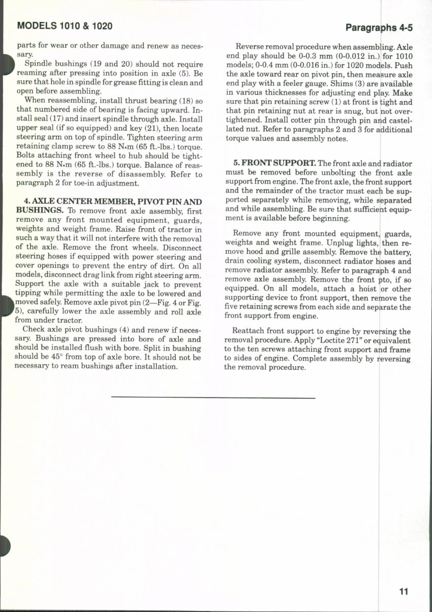
6. A cross section drawing of the manual steering
gear assembly is shown in Fig 6. Note that the steer-
ing gears are contained within a cavity in the top of
the clutch housing and that the steering shaft ex-
tends through the clutch housing. The steering ratio
is 10:1 for all 1010 models and 13:1 for all 1020
models. Some differences will be noticed, including
the number of teeth on gears (12 and 15—Fig, 7) and
shaft (17) may be straight on some models.
7. R&R AND OVERHAUL. To service steering
gear, it is necessary to remove the steering wheel,
instrument panel cover and fuel tank. Disconnect
brake and clutch rods from pedals and pedal cross
Fig. &^Cross section drawing of steering gear typicai of
ali modeis. Refer to Fig. 7 for exploded view.
shaft, then unbolt and remove the steering wheel
shaft support (24—Fig. 7). Remove clamp rings- (7)
and slide boot (8) up to uncover universal joint. Re-
move lower retaining ring (4) and use a punch to d rive
lower pin (6) from universal joint, then separate
universal joint (5) from pinion shaft (12). Notice that
pins (6) are stepped and must be removed toward
larger end. Remove screws attaching cover (9) to
transmission housing, then remove cover, leaving
pinion shaft (12) in transmission housing. Pinion
shaft (12) and quadrant gear (15) can be removed
together after removing retaining nut (14). Steering
arm shaft (17) can be removed after splitting tractor
between engine and clutch housing, then removing
the engine clutch shaft.
When reassembling, front wheels must be straight
ahead and steering pinion (12) must be in center of
teeth on quadrant gear (15). Tighten nut (14) to 59-78
N.m (43-58 ft.-lbs.) torque. If tab lockwasher is in-
stalled under nut (14), flat side of nut should be
toward top and tab of washer should be bent up to
lock retaining nut. Some models may be equij^ped
with self-locking nut or two special nuts. Fill gear
cavity half full with multi-purpose lithium ])ase
grease. Nut for clamp bolt (22) retaining steering arm
(21) to lower end of shaft should be tightened to 78-90
N.m (57-68 ft.-lbs.) torque. The steering arm (21) o
some models is retained with a nut threaded to shaft
similar to the type (14) at upper end. The larger
retaining nut should be tightened to 98-117 N.m
(72-87 ft.-lbs.) torque.
POWER ASSIST
Models So Equipped
8. Power assisted steering is available and may be
installed on any model. Refer to Fig. 8 for view of flow
divider valve (1), steering valve and steering assist
cyhnder assembly (3), connecting hydraulic lines and
attaching brackets. Most service will consist of re-
moval, disassembly, cleaning and reassembly using
new seals. Refer to Fig. 9 for exploded view of cylinder
and valve unit.
To remove the power steering unit, raise front of
tractor so that weight is removed from the lront
wheels. Disconnect hydraulic lines (2 and 8—Fig. 8),
then tum steering wheel from lock to lock to dis-
charge oil from steering cylinder. Disconnect steering
unit from anchor bracket (4), steering arm (5) and
drag link (7).
To renew steering cylinder seals, remove ball joint |
end from cylinder rod (41—Fig. 9). Flatten the locking
groove on the cylinder, then unscrew cap and bearing
assembly (43) from cylinder (36). Withdraw cylinder
12
MODELS 1010 & 1020
Paragraph 8 (Cont.)
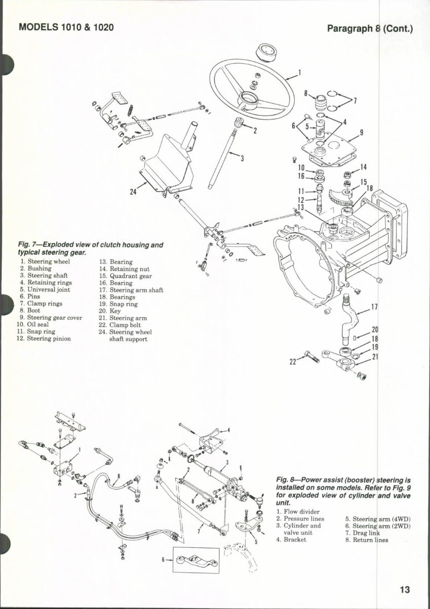
Fig. 7^Expioded view of dutch housing and
typicai steering gear.
1. Steering wheel
2. Bushing
3. Steering shaft
4. Retaining rings
5. Universal joint
6. Pins
7. Clamp rings
8. Boot
9. Steering gear cover
10. Oil seal
11. Snap ring
12. Steering pinion
13. Bearing
14. Retaining nut
15. Quadrant gear
16. Bearing
17. Steering arm shaft
18. Bearings
19. Snap ring
20. Key
21. Steering arm
22. Clamp bolt
24. Steering wheel
shaft support
22'
Fig. 8—Power assist (booster) steering is
instaiied on some models. Refer to Fig. 9
for expioded view of cyiinder and vaive
unit.
1. Flow divider
2. Pressure lines
3. Cylinder and
valve unit
4. Bracket
I
5. Steering arm (4WD)
6. Steering arm (2WD)
7. Drag link
8. Return lines
13
Paragraph 8 (Cont.)
MASSEY-FERGUSON
IS
14
26
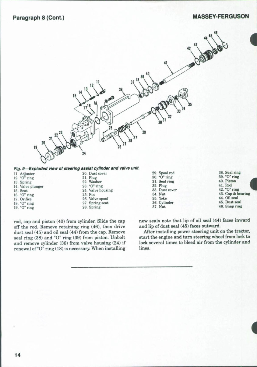
Fig. 9-~Explod0d view of steering BBSist cylinder and valve unit,
11. AcUuster 20. Dust cover 29. Spool rod
12. "O" ring 21. Plug 30. "0" ring
13. Spring 22. Washer 31. Seal ring
14. Valve plunger 23. "O" ring 32. Plug
15. Seat 24. Valve housing 33. Dust cover
16. "O" ring 25. Pin 34. Nut
17. Orifice 26. Valve spool 35. Yoke
18. "O" ring 27. Spring seat 36. Cylinder
19. "O" ring 28. Spring 37. Nut
38. Seal ring
39. "O" ring
40. Piston i
41. Rod I
42. "O" ring ^
43. Cap & bearing
44. Oil seal
45. Dust seal
46. Snap ring
rod, cap and piston (40) from cylinder. Slide the cap
off the rod. Remove retaining ring (46), then drive
dust seal (45) and oil seal (44) from the cap. Remove
seal ring (38) and "O" ring (39) from piston. Unbolt
and remove cylinder (36) from valve housing (24) if
renewal of "O" ring (18) is necessary. When installing
new seals note that lip of oil seal (44) faces inward
and lip of dust seal (45) faces outward.
After installing power steering unit on the tractor,
start the engine and tum steering wheel from lock to
lock several times to bleed air from the cylinder and
lines.
14
You're Reading a Preview
What's Included?
Fast Download Speeds
Online & Offline Access
Access PDF Contents & Bookmarks
Full Search Facility
Print one or all pages of your manual
$52.99
Viewed 71 Times Today


Secure transaction
What's Included?
Fast Download Speeds
Online & Offline Access
Access PDF Contents & Bookmarks
Full Search Facility
Print one or all pages of your manual
$52.99
This manual is suitable for both first-time owners and amateur enthusiasts, as well as professional technicians. It is designed in an easy-to-read format and provides comprehensive information necessary for accurate procedure execution. It is recommended to keep this service manual accessible and refer to it regularly. Adhering to routine and preventive maintenance outlined in the manual will contribute to time and cost savings by averting premature failure and unnecessary repairs.
- BRAKES
- CLUTCH
- COOLING SYSTEM
- DIESEL FUEL SYSTEM
- DIFFERENTIAL
- DIFFERENTIAL LOCK
- ELECTRICAL SYSTEM
- ENGINE
- FINAL DRIVE
- FRONT SYSTEM
- HYDRAULIC SYSTEM
- POWER TAKE-OFF
- TRANSMISSION
File Format: PDF
Compatibility: All Versions of Windows & Mac
Language: English
Requirements: Adobe Reader


