Massey Ferguson GC2300 Tractor Service & Repair Manual
What's Included?
Lifetime Access
Fast Download Speeds
Online & Offline Access
Access PDF Contents & Bookmarks
Full Search Facility
Print one or all pages of your manual
INTRODUCTION 79023519 01-1 INTRODUCTION Contents INDEXING ....................................................................................................... 01- 2 SPECIAL TOOLS ............................................................................................. 01- 2 REPAIRS & REPLACEMENTS ........................................................................ 01- 2 REPAIR TIME SCHEDULE .............................................................................. 01- 2 AMENDMENTS ............................................................................................... 01- 2 SAFETY PRECAUTIONS ................................................................................ 01- 3 GENERAL INFORMATION .............................................................................. 01- 4 Model Name and Identification Numbers ........................................................................... 01- 4 Chasis ............................................................................................................................... 01- 5 Engine Model and Serial Number ...................................................................................... 01- 5 Specifications .................................................................................................................... 01- 6 TRANSMISSION & RELATED PARTS AGRI TIRE (REVOLUTION OF SHAFTS) ....................................................... 01- 9 Drive System ..................................................................................................................... 01- 9 PTO System ...................................................................................................................... 01- 9 Gear Pump System ........................................................................................................... 01- 9 TURF TIRE (REVOLUTION OF SHAFTS) .................................................... 01- 10 Drive System ................................................................................................................... 01- 10 PTO System .................................................................................................................... 01- 10 Gear Pump System ......................................................................................................... 01- 10 LUBRICATION & PERIODIC MAINTENANCE .............................................. 01- 12 SPECIFICATIONS & CAPACITIES ENGINE OIL .................................................................................................. 01- 12 Engine Coolant ................................................................................................................ 01- 12 Fuel Tank ......................................................................................................................... 01- 12 Transmission & Differential Housing (Including Hydraulic System) ................................. 01- 12 Front Axle (4-WD Only) ................................................................................................... 01- 12 Grease Fittings ................................................................................................................ 01- 12 PERIODIC MAINTENANCE SCHEDULE ...................................................... 01- 12 MAINTENANCE SCHEDULE ........................................................................ 01- 13 LUBRICATION AND FILL POINTS ................................................................ 01- 14 STANDARD TORQUE CHART ...................................................................... 01- 15 SEALANT & ADHESIVES .............................................................................. 01- 16 CONVERSION TABLES ................................................................................ 01- 17
INTRODUCTION 01-2 79023519 INTRODUCTION The purpose of this manual is to assist dealers and distribute in the efficient repair and maintenance of Massey Ferguson and AGCO machinery. Carrying out the procedures as detailed, together with the use of special tools where appropriate will enable the operations to be completed within the time stated in the repair time schedule. NOTE: To assist with locating information, each division of the manual is preceded by a contents page listing the operations in numerical order. Each operation is given in sequential order. To complete the operation in the minimum time it is essential that these instructions are preformed in given order unless otherwise stated. When applicable, the callout numbers in the text reference components in the appropriate illustration. Where performance of an operation requires the use of a special tool, the tool is called out in that operation. INDEXING For convenience, the manual is divided into parts sections with each page number bearing the part and section number. Page numbers are located at top outside of each page. Beneath the page number is written title of manual division. Page Number Example: 7A-15 Part 7 Section A, Page 15 This simplifies cross-referencing and enables the subject to be found easily. NOTE: Page numbers will be consecutive within each sub-section. A void of page numbers may be used between these sub-sections in order to provide space for future amendments and also to indicate the beginning/end of adjacent sub- sections. SPECIAL TOOLS Where the use of a special tool is specified in an operation, the tool number will be shown under the operation. The use of the special tools mentioned in the text contributes to a safe, efficient and profitable repair. Some operations are impracticable without their use. Make certain proper tools are available when starting the job. REPAIRS & REPLACEMENTS When service parts are required, it is essential that only genuine Massey Ferguson and AGCO replacements are used. Attention is particularly drawn to the following points concerning repairs and the fitting of replacement parts accessories: Safety features embodied in the tractor may be impaired if other than genuine parts are fitted. In certain territories, legislation prohibits the fitting of parts not to the tractor manufacturer’s specification. Torque wrench setting figures given in the Workshop Manual must be strictly adhered to. Locking devices where specified must be fitted. If the efficiency of a locking device is impaired during removal it must be renewed. The tractor warranty may be invalidated by the fitting of other than genuine Massey Ferguson, AGCO, and Challenger parts. All Massey Ferguson and AGCO replacements have the full backing of the manufacturer’s warranty. Massey Ferguson and AGCO Distributors and Dealers are obliged to supply only genuine service parts. REPAIR TIME SCHEDULE The operations listed in the Repair Time Schedule refer to those described in this manual. The time set against each operation in the schedule is established by performing the actual operations on standard machines using special tools where applicable. The Repair Time Schedule for use with this manual is issued as a separate publication. NOTE: Repair Time Schedules are issued to Massey Ferguson and AGCO Distributors and Dealers only and are not for general publication. AMENDMENTS Under normal conditions, revised pages issued carry the same number as the existing pages requiring amendment. The new pages are inserted in place of the existing ones. The old pages should then be discarded. In some cases additional pages or completely new sections may be issued. These pages are to be inserted immediately following the page carrying the next lowest page number, or section number as appropriate. Where new pages are required to be positioned between existing pages, the new page numbers will contain a suffix letter: Example New Page Number: 7A-16a. This page is inserted after existing page number 7A-16 and before page number 7A-17. Correspondingly a further new page numbered 7A-16b would be positioned after 7A-16a but before 7A-17. NOTE: Service Bulletins and Amendment Sheets are issued to the Massey Ferguson and AGCO Distributors and Dealers only and are not for general publication.
INTRODUCTION 79023519 01-3 SAFETY PRECAUTIONS • Make sure that all personnel are in a safe position before starting the engine, or operating ANY of the controls. • Always stop the engine before leaving the operator’s platform. • Wait for all moving parts to stop COMPLETELY before starting any work on the tractor. • Before starting service procedures, attached equipment should be resting on the ground and all hydraulic control levers operated back and forth several times with the engine stopped. • If it becomes necessary to go under raised attachment (i.e: to perform adjustments, etc.), safety standards must be used to support the attachment. • Make sure the battery ground cable is disconnected before working on or near the electrical system or electrical system components. • Keep hands, feet and clothing a safe distance away from moving belts, pulleys and other moving parts. Make sure all safety shields are installed. • Be extra careful when performing any checks, inspections, adjustments or tests that require operating the engine, the hydraulic controls, OR with the machine in motion. • Make sure dependable jacks of adequate lifting capacity AND suitable stands (or wooden blocking) are used to securely block up the machine when removing any of the wheels or axles. CAUTION: PERSONAL INJURY MAY RESULT IF THESE PRECAUTIONS ARE NOT FOLLOWED. Look for this symbol to point out important safety precautions. It means - ATTENTION! BECOME ALERT! YOUR SAFETY IS INVOLVED. • Before any attempt is made to disconnect or remove any hydraulic component, make sure the hydraulic pressure within the system is relieved and the engine is stopped. • Carry out the repair procedures in a “common sense” manner. Safety procedures cannot be over- emphasized when working on, or around machinery, especially when working on engine driven and/or hydraulically actuated equipment. • Safety also depends upon the skill of the service man in the use of tools and other shop equipment while performing the recommended service procedures. • Exercise extreme caution when testing hydraulic or fuel system components as fluid ejected under high pressure can easily penetrate skin causing serious infection. • When it is necessary to remove hoods, shields, ROPS, etc. to conduct repair operation, all items must be reinstalled to unit and secured in original fashion. • Modification of ROPS is not permissible. Do not weld, drill or modify ROPS in any manner. Damaged or modified ROPS must be replaced.
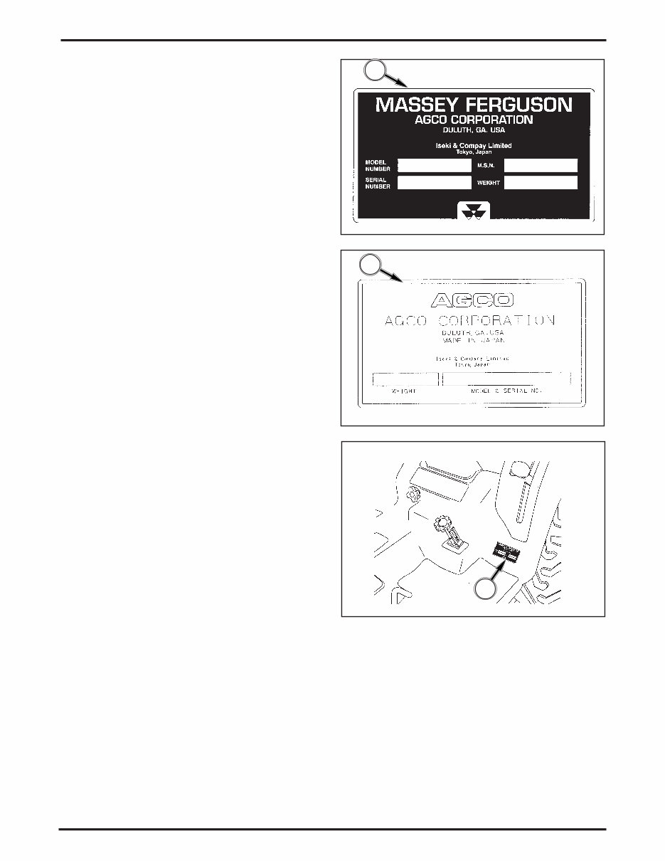
INTRODUCTION 01-4 79023519 FIG. 1 I-6006 FIG. 2 I-6090 1 GENERAL INFORMATION Model Name and Identification Numbers FIGS. 1, 2 & 2a: The name plate (1) which gives the model name, type, production serial number, and production year of the machine, is located on the left- hand side of the rear fender (2). FIG. 2a I-7196 2 1
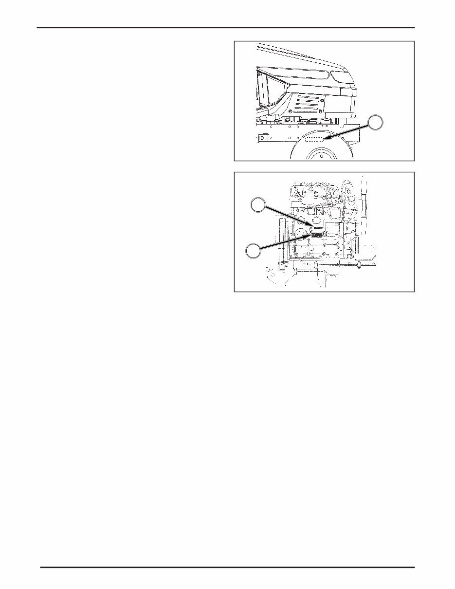
INTRODUCTION 79023519 01-5 FIG. 4 I-7197 FIG. 3 I-7198 1 1 2 Engine Model and Serial Number FIG. 4: The engine model name (1) is cast into the left- hand side wall of the cylinder block. The serial number (2) is punched into the left-hand side wall of the cylinder block. Chasis FIG. 3: The chassis number is punched on the plate provided on the right-hand side of the chassis (1).
INTRODUCTION 01-6 79023519 ENGINE Make Iseki Diesel Model E3112-B12 Type Indirect injection, overhead valve Aspiration Natural Displacement 68.5 cu. in. (1123 cc) Number of Cylinders 3 Bore 3.08” (78.2 mm) Stroke 3.07” (78.2 mm) Engine Horsepower (Gross) 22.5 HP (16.5kW) @ 2600 rpm Net 21.6 PS (15.9 kW) @ 2600 rpm PTO Horsepower (Estimate) 17.5 @ PTO rpm Firing Order 1-3-2 Compression Ratio 22.5 to 1 Low Idle Speed 1250 to 1300 rpm High Idle Speed 2760 to 2860 rpm Valve Clearance (Cold): Intake 0.010” (0.25 mm) Exhaust 0.010” (0.25 mm) Air Cleaner Single stage, dry element Engine cooling Liquid, forced circulation Cold Starting Aid Glow plugs (3) TRANSMISSION Primary Hydrostatic Range 2 speed constant mesh (2 forward, 2 reverse) Clutch None Brakes Mechanically actuated sealed wet disk Specifications
INTRODUCTION 79023519 01-7 POWER TAKE-OFF (PTO) Type Independent, engine driven Control Hydraulic control Clutch Mechanically engaged, multi-plate wet disk Rear PTO; Shaft 1.375” (35mm) diameter, six spline Output Clockwise rotation Engine Speed @ 540 PTO rpm 2532 rpm Mid PTO; Shaft 1.000” (25.4) diameter, fifteen spline Output Clockwise rotation Engine Speed @ 2100 PTO rpm 2476 rpm HYDRAULICS Steering System Hydrostatic (power) Pump Transmission-mounted gear pump with flow divider Maximum Output 2.0 U.S. gals./min. (7.5 I/min.) Pressure Relief valve setting 1209 psi (8335 kPa) Main Hydraulic System Transmission-mounted gear pump Maximum Output 6.1 U.S. gals./min. (23.1 I/min.) Pressure Relief valve setting 1920 psi (13244 kPa) Rear Linkage; Type Three-point hitch Size Category 1 Control Position control Lift Capacity 1191 lbs. (540 kg) measured at ball ends ELECTRICAL SYSTEM System Voltage 12 volt, negative (-) ground Battery cca @ 0F (-18) 390 cca Charging 40 amp alternator with internal regulator/rectifier
INTRODUCTION 01-8 79023519 TREAD WIDTH SETTINGS Front 4WD Ag. Tires (“Dished In” Only) 36.6” (930 mm) Turf Tires (“Dished In” Only) 36.6” (930 mm) Rear 4WD Ag. Tires (“Dished In “ Only) 33.1” (840 mm) Turf Tires (“Dished In” Only) 33.1” (840 mm) MAXIMUM AXLE LOADING Front 4WD 1940 lbs (880 kg) Rear Axle 2094 lbs. (950 kg)
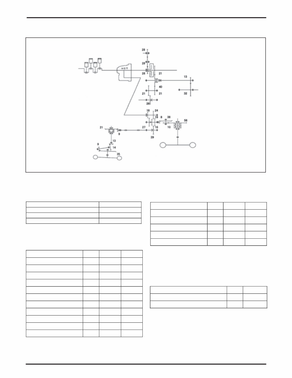
INTRODUCTION 79023519 01-9 FIG. 5 I-9273 Diameter of front wheel 457 [mm] Diameter of rear wheel 665 [mm] Engine Speed [RPM] 2600 HST Pump Capacity (cc) 21.0 HST Motor Capacity (cc) 21.0 HST Volumetric Efficiency 95% L H Input Shaft RPM 2600 2600 HST Output Shaft RPM 2470 2470 Drive Pinion RPM 1463.70 3120 Wheel Pinion RPM 308.15 656.84 Rear Wheel Shaft RPM 55.03 117.29 Rear Wheel Speed Km/h 6.90 14.70 Front Drive Shaft RPM 807.56 1721.38 Front Ring Gear RPM 346.10 737.73 Front Kingpin RPM 321.38 685.04 Front Wheel Shaft RPM 82.64 176.15 Front Wheel Speed Km/h 7.12 15.17 Rear Mid Input Shaft RPM 2600 2600 PTO Counter Shaft RPM 1365 1365 Rear PTO Shaft RPM 554.53 Mid PTO Idle Gear RPM 2600 Mid PTO Shaft RPM 2100 Input Shaft RPM 2600 Counter Gear RPM 2414.29 Input SHaft RPM 2414.29 TRANSMISSION & RELATED PARTS AGRI TIRE (REVOLUTION OF SHAFTS) FIG. 5: Drive Train Diagram shown. Drive System PTO System Gear Pump System NOTE: Front axle lead ratio is 3.12%.
INTRODUCTION 01-10 79023519 FIG. 6 I-9273 Diameter of front wheel 450 [mm] Diameter of rear wheel 648 [mm] Engine Speed [RPM] 2600 HST Pump Capacity (cc) 21.0 HST Motor Capacity (cc) 21.0 HST Volumetric Efficiency ( - ) 0.95 L H Input Shaft RPM 2600 2600 HST Output Shaft RPM 2470 2470 Drive Pinion RPM 1463.70 3120 Wheel Pinion RPM 308.15 656.84 Rear Wheel Shaft RPM 55.03 117.29 Rear Wheel Speed Km/h 6.72 14.33 Front Drive Shaft RPM 807.56 1721.38 Front Ring Gear RPM 346.10 737.73 Front Kingpin RPM 321.38 685.04 Front Wheel Shaft RPM 82.64 176.15 Front Wheel Speed Km/h 7.01 14.94 Rear Mid Input Shaft RPM 2600 2600 PTO Counter Shaft RPM 1365 1365 Rear PTO Shaft RPM 554.53 Mid PTO Idle Gear RPM 2600 Mid PTO Shaft RPM 2100 Input Shaft RPM 2600 Counter Gear RPM 2414.29 Input SHaft RPM 2414.29 TURF TIRE (REVOLUTION OF SHAFTS) FIG. 6 &7: Drive Train Diagram shown. Drive System PTO System Gear Pump System NOTE: Front axle Lead Ratio is 4.29 (%).
Massey Ferguson GC2300 Tractor Service & Repair Manual
The Massey Ferguson GC2300 Tractor Service & Repair Manual is an essential resource for anyone tasked with maintaining or repairing their MF GC2300 Series tractor. Whether you are a professional mechanic or a dedicated DIY owner, this manual offers precise technical information and step-by-step procedures to ensure your machine stays in top working condition.
Covering everything from general service guidelines and maintenance schedules to drivetrain systems, lubrication points, torque charts, and electrical troubleshooting, this manual is packed with highly detailed content straight from the manufacturer. It includes the full specifications of the Iseki Diesel E3112-B12 engine and hydrostatic transmission systems found in these tractors.
With clear illustrations, exploded diagrams, and easy-to-follow instructions, this manual gives you the confidence to handle everything from routine servicing to more involved mechanical repairs.
Content Overview:
Special Tools
Repairs and Replacements
Repair Time Schedule
Safety Precautions
General Information and Specifications
Transmission and Related Parts
Drive Systems (Agri Tire and Turf Tire Models)
PTO and Gear Pump Systems
Lubrication and Periodic Maintenance
Engine Oil and Coolant Specifications
Maintenance Schedule and Lubrication Points
Torque Specifications
Sealants, Adhesives, and Conversion Tables
This manual ensures you always have reliable service information close at hand. Avoid costly downtime and repairs by following the official service instructions designed for your machine.
Printable: Yes Language: English Compatibility: Windows, Mac Requirements: PDF reader software
Recently Viewed
5,521,897Happy Clients
2,594,462eManuals
1,120,453Trusted Sellers
15Years in Business
Price:
Actual Price:
Massey Ferguson GC2300 Tractor Service & Repair Manual