1947-1954 Massey-Harris Pony Tractor Parts Catalog
What's Included?
Lifetime Access
Fast Download Speeds
Online & Offline Access
Access PDF Contents & Bookmarks
Full Search Facility
Print one or all pages of your manual
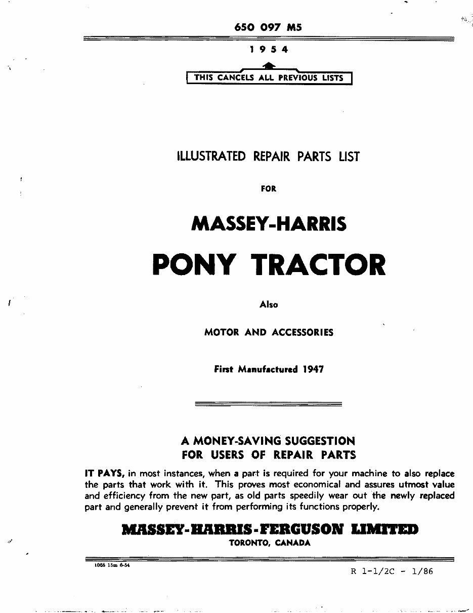
650 097 M5 1 954 • - lit I TH IS CANCELS ALL PREVIOUS LISTS .. A MONEY-SAVING SUGGESTION FOR USERS OF REPAIR PARTS IT PAYS, in most instances, when a par.t is required for your machine to also replace the parts that work with it. This proves most economical and assures utmost value and efficiency from the new part, as old parts speedily wear out the newly replaced part and generally prevent it from performing its functions properly. IIAISEY-BABBlS-rEBGUSON I.IMr.-ED TORONTO. CANADA ILLUSTRATED REPAIR PARTS LIST FOR MASSEY-HARRIS PONY TRACTOR Also MOTOR AND ACCESSORIES Fint Manufactured 1947 1068 15m 6-54 R 1-1/2C - 1/86 .", ---
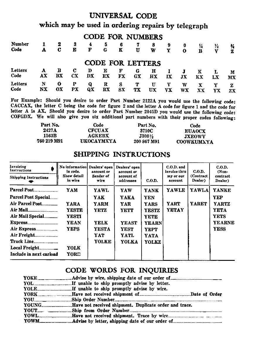
UNIVERSAL CODE which may be used in ordering repairs by telegraph CODE FOR NUMBERS Number 1 2 3 5 6 7 8 9 o % Vz % Code A C E F G K U W Y B V z " o CODE FOR LETTERS Letters Code A AX B BX C CX D DX E EX F FX G GX H HX I IX J JX K KX L LX l\f MX Letters Code N NX o OX P PX Q QX R RX S SX T TX U UX V VX W WX X XX Y YX Z ZX For Example: Should you desire to order Part Number 2122A you would use the following code: CACCAX, the letter C being the code for figure 2 and the letter A code for figure 1 and the code for letter A is AX. Should you desire to order Part Number 2045D you would use the following code: COFGDK. We will also give you six additional part numbers with their proper codes following: Part No. Code Part No. Code 2427A CFCUAX 3710C EUAOCX 1563B AGKEBX J30S Vz JXEOWV 760219 M91 UKOCAYMXYA 200867 M91 COOWKUMXYA SHIPPING INSTRUCTIONS Invoicing • No information Instructions In code. Show detail Shipping Instructions in wire .- Parcel Post __________________ Parcel Post SpeciaL ____ Air Parcel PosL ___ Air MaiL-____________ Air Mail SpeciaL__ Express _____________ Air Express ____________ Air Freight______________ Truck Line ___________ Local FreighL_______ Include in next carload Dealeu' open account or Sender of wire YAWL YAK YARM YETZ YELK YESTA YAT YOLKE Dealers' open account or account of addressee YAW YAKA YAR YETT YEAST VEST YATL YOLKA C.O.D. YANK YEN YARS YESTZ YETE YEARN YEPT YATA YOLKZ C.O.D. and Invoice thru my or our account YAWLE YART YETAY C.O.D. C.O.D. (Non- (Contract contract Dealer) Dealer) YAWLA YANKE YEP YARET YARTZ YETA VETS YEARNE YESS YAM YARA YESTE YESTI YEAN YEPS YOLK YORn CODE WORDS FOR INQUIRIES YOKE. Advise by wire, shipping date of our order of _________ _ yOL______________ 1f unable to ship promptly advise by letter. yOLE ___________1f unable to ship promptly advise by wire. YORK. ______________ Have not received shipment oL_________________.______Date of Order YOU______---------------..Bhip Order N umber _______________.__________________________________- ____ _ YOUNG____ Have not received shipment. Duplicate order and trace. YOUT______.___Ship from Order Number _________________________________________ YOWL___ __..Have Dot received shipment. Trace by wire _____________________________ _ YOWM AdTise by letter, shipping date of our order
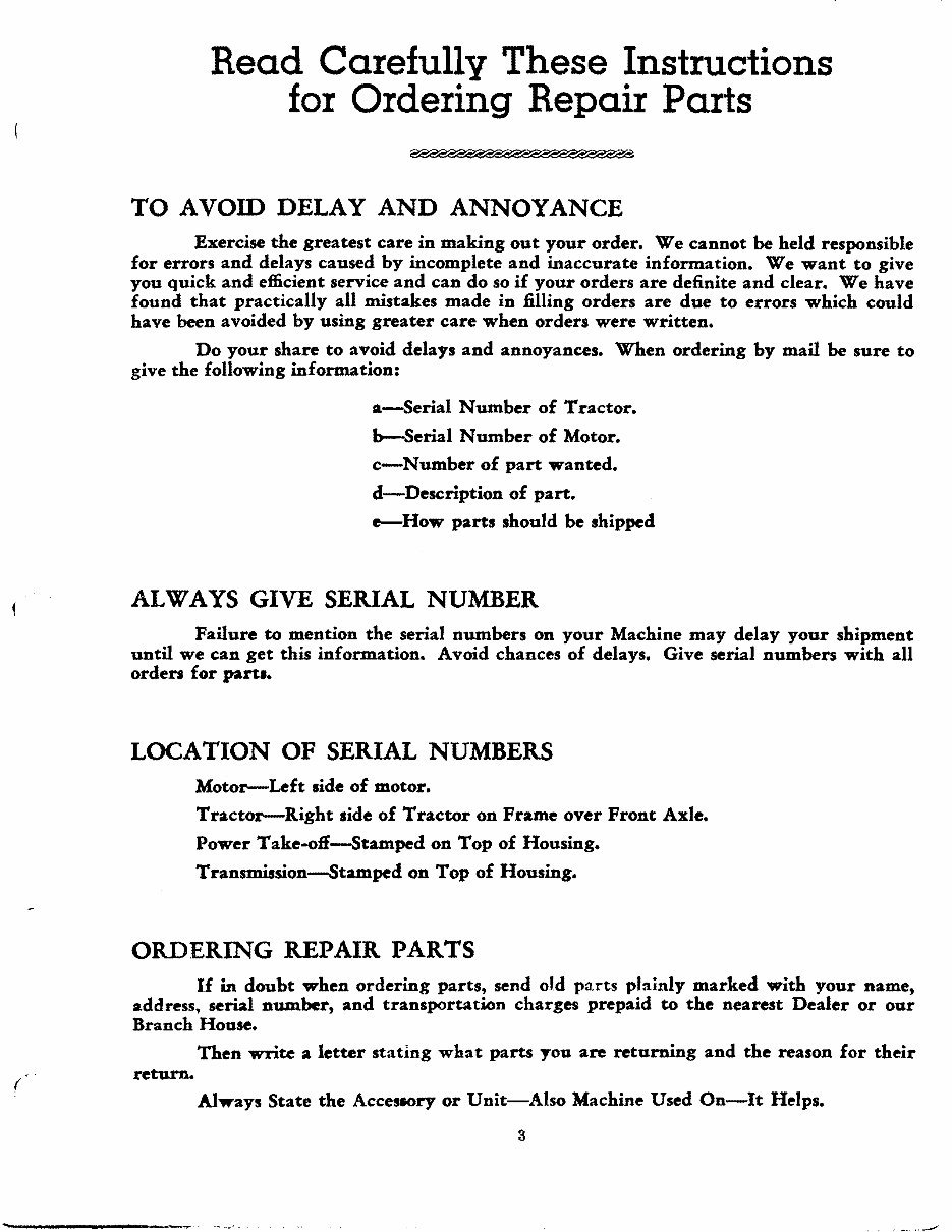
Read Carefully These Instructions for Ordering Repair Parts TO AVOID DELAY AND ANNOYANCE Exercise the greatest care in making out your order. We cannot be held responsible for errors and delays caused by incomplete and inaccurate information. We want to give you quick and efficient service and can do so if your orders are definite and clear. We have found that practically all mistakes made in filling orders are due to errors which could have been avoided by using greater care when orders were written. Do your share to avoid delays and annoyances. When ordering by mail be sure to give the following information: ,,-Serial Number of Tractor. b-Serial Number of Motor. c-Number of part wanted. d-Description of part. e--How parts should be shipped ALWAYS GIVE SERIAL NUMBER Failure to mention the serial numbers on your Machine may delay your shipment until we can get this information. Avoid chances of delays. Give serial numbers with all order. for part•• LOCATION OF SERIAL NUMBERS Motor-Left .ide of motor. Tractor-Right side of Tractor on Frame over Front Axle. Power Take.off-5tamped on Top of Housing. Transmission-5tamped on Top of Housing. ORDERING REPAIR PARTS If in doubt when ordering parts, send old pa.rts plainly marked with your name, address. serial number, and transportation charges prepaid to the nearest Dealer or our Branch House. Then write a letter stating what parts you are returning and the reason for their return. Always State the AcceslOry or Unit-Also Machine Used On-It Helps. 3 ( ... . , ..---'
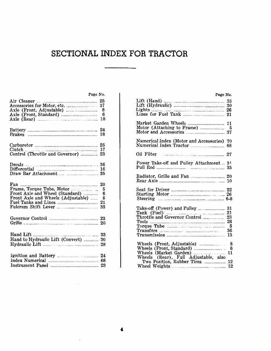
SECTIONAL INDEX FOR TRACTOR Page No. Air Cleaner _____________________________________________ 25 Accessories for Motor, etc. _________________________ 37 Axle (Front, Adjustable) _________________________ 8 Axle (Front, Standard) _________________________ 6 Axle (Rear) __________________________________________________ 10 Battery _______________________________________________________ 24 Brakes ____________________ _____ _ ___ ______________________ ___ 18 Carburetor 25 CI utch ___ ________________________________________________________ 17 Control (Throttle and Governor) ______________ 23 Decals ___ __ _ _____ _ ________________________________________ _ ____ ___ _ 36 Differential 16 Draw Bar Attachment __________________________ ._ 35 Fan _________________________________________________ .. ____ ________ 20 Frame, Torque Tube, Motor ____________________ 5 Front Axle and Wheel (Standard) ____________ 6 Front Axle and Wheels (Adjustable) _.____ 8 Fuel Tanks and Lines __________________________________ 21 Fulcrum Shift Lever __________________________________ 33 Governor Control 23 Grille ______________________________________________________________ 20 Hand Lift _____________ .__________________________________ 33 Hand to Hydraulic Lift (Convert) ___________ 30 Hydraulic Lift 28 Ignition and Battery _______________ 24 Index Numerical ______________________________________ 68 Instrument Panel ________________________________________ 23 Page No. Lift (Hand) _________________________________________________ 33 Lift (Hydraulic) ________________________________________ 30 Ligh ts ---___________ ______________________ ______________________ 26 Lines for Fuel Tank 21 Market Garden Wheels ____________________________ 11 Motor (Attaching to Frame) ____________________ 5 Motor and Accessories 37 Numerical Index (Motor and Accessories) 70 Numerical Index Tractor ________________________ 68 Oil Filter -- - .------ ----_______________ _____________________ 27 Power Take-off and Pulley Attachment __ 31 Pull Rod --------______________________________________________ 35 Radiator, Grille and Fan __________________________ 20 Rear Axle --___________________________________________________ 10 Seat for Driver ___________________________________________ 22 Starting Motor _________________________________________ 26 Steering ___ _______ ________________________________________ 6-8 Take-off (Power) and Pulley ______________________ 31 Tank (Fuel) ___________________________________________ 21 Throttle and Governor Control ________________ 23 Tools ____________________________ ___ _____________________________ 26 Torque Tube ___________ _________________________________ 5 Transfers ____________ ____________________________________ 36 Transmission ____________________________________________ 13 Wheels (Front, Adjustable) _ 8 Wheels (Front, Standard) _______________________ _ 6 Wheels (Market Garden) ____-. _________________ 11 Wheels (Rear), Full Adjustable, also Two Position, Rubber Tires - _______________ 12 Wheel Weights __________________________________________ 12
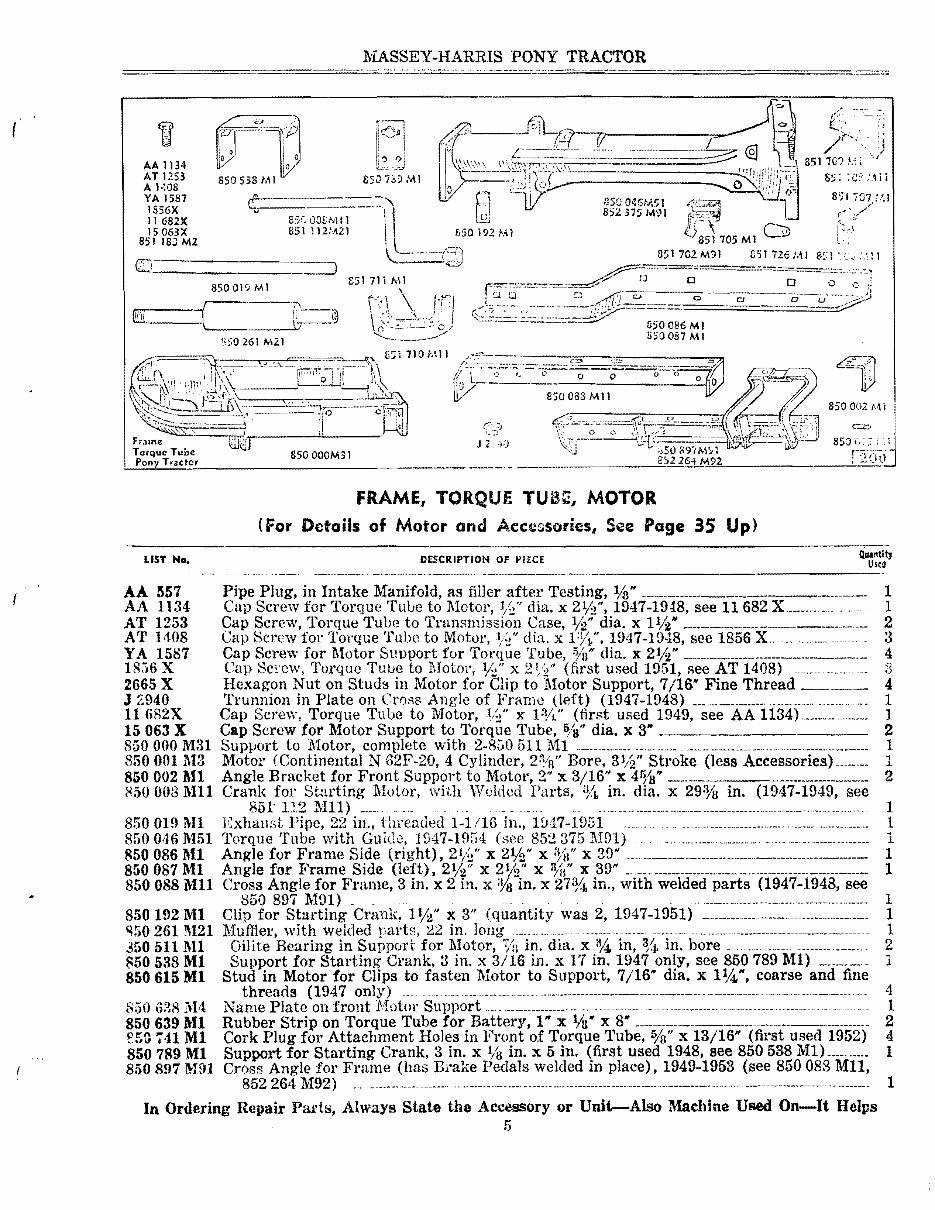
MASSEY-HARRIS PONY TRACTOR . -- .. .. ,.-.... ( l2_I)J AA 1134 AT 1253 !l507d'JMl A 1·:08 YA 1587 IS56X 11682X 8S(OO&MIJ 15063X 851 l12t·ALI 851 IS,;) M2 C 850019 M1 '-7\ fii'T: ill:!J,___ \7-_ 1 ;1 gSO 261 M2.1 IVI 850002 Ml i J;: \.) I.-.:...:.:.:.L..;..:..::.::..:.:::.:._________________ ._ I FRAME, TORQUE MOTOR (For Details of Motor and Accessories, See Page 35 Up) LIST No. DESCRIPTION OF i'IECE ----_. --- -------- ._-_._- ---------..--------------- AA 557 Pipe Plug, in Intake Manifold, as filler after Testing, 1/a'" 1 AA 1134 Cap Screw for Torque Tulie to 1\1otor, %" diu. x 2%", 1947-1948, see 11682 1 AT 1253 Cap Screw, Torque Tube to Transmission Case, 1/:>" dia. x llAt 2 AT H08 Cap 8crew fot' Torque Tube to Motor, %" diu. x 1947-19,18, see 1856 3 YA 1587 Cap Screw for Motor Support for Torque Tube, %" di::!.. x 21/2" __________________________ 4 Ur,6 X Cap 8c!'cw, Torque TUlle to MotOl',%" x (first used 1951, flee AT 1408) ___ 3 2665 X Hexagon Nut on Studs in Motor for Clip to Motor Support, 7/16" Fine Thread _.__ 4 J 7.940 Trunnion in Plate on Crogs Angle of Frame (left) (l947-1948) ___ ._... _________.... ________ . ____ .... 1 11 6fl2X Cap Screw, Torque Tube to Motor, %" x 1%" (fir8t used 1949, see AA 1134).______________ 1 15 063 X Cap Screw for Motor Support to Torque Tube, 6/ S " dia. x 3" _ 2 850 000 M31 Support to Motor, complete with 2-850 511 lVIJ ________ . ____ .. ________ .________ .________ ._.____________________ 1 8500011\13 Motor (Continental N 62F-20, 4 Cylinder, 2: 1I n" Bore, SlAt Stroke (less Accessories) _____ .. _ 1 8500021\11 Angle Bracket for Front Support to Motor, 2'" x 3/16" x 4%'" _. __________ _____.__________ 2 0081\'111 Crank for Starting :Motor, with Welded Parts, in. dia. x 29% in. see 851' 112 Mll) _____ _ __ .. .. ____ .________ ..___ .. ____ . ______ ._. _____ ._. __ . ___ ... ____ 1 850019 Ml Exhaust Pipe, 22 in., threaded 1-1/16 in., I!H7-1D51 .. __ . ___ ._. _____________. ________________________ .____ 1 850046 M51 Torque Tube with Guide, 1947-1954 (see 852375M!)1) '. __ ._. ____ . _______ .. ____________________ 1 8500861\11 Angle for Frame Side (right), 21;;( x 21/2" X %" x 29" ____ _________ ______ _____ .. ___________ 1 850087 Ml Angle for Frame Side (left), 2%" x 2%" x 'HI" x. 39" .. ___________________ . _____. _____ __________________ 1 8500881\111 Cross Angle for Frame, 3 in. x 2 in. x % in. x in., with welded parts (1947-1948, see 850 897 M91 ) _________________. _______ .. ___ 1 850192 Ml Clip for Starting Crank, 1%" x 3" (quantity was 2, 1947-1951) - ____ . _____ ___________._________ 1 Muffler, with welded parts, in. long .. _... _ _ _____________. ______ ._._. _________. _______. _______ .________________ 1 261M21 3505111\11 850538 Ml 850615 Ml 850 lH4 8506391\-11 ';41 Ml 850789 Ml Oillte Bearing in Support for Motor, % in. dia. x %. in, %. in. bore. .._. ________ ._____ ._ 2 Support for Starting Crank, 3 in. x 3/16 in. x rl in. 1947 only, see 850789 Ml) ________ 1 Stud in Motor for Clips to fasten Motor to Support, 7/16" dia. x 11,4", coarse and fine threads (1947 only) __ _ __ .___ ._____ ._... ___________________________________ . _____ .. _____ .- ____.. ____.. _____ .. .... 4 Name Plate on front Motor Support _________ . ______________________ . ________________ .---------- .. - 1 Rubber Strip on Torque Tube for Ba.ttery, 1" x Vs" x 8' ________________ ________________ 2 Cork Plug for Attachment Holes in Front of Torque Tube, %t" x 13/16" (first used 1952) 4 Support for Starting Crank, 3 in. x % in. x 5 in. (first used 1948, see 850538 Ml} ________. 1 850897 ""Ell Cross Angle for Frame (has Brake Pedals welded in place), 1949-1953 (see 850088 Mll, 852 264 M92) ... ________. ___. _______ -- -. ----- ...... ---.. ---- .. -----.------------- .. ---------- In Ordering Repair Pads, Always State the Accessory or Unit-Also Machine Used On-It Helps 5 1
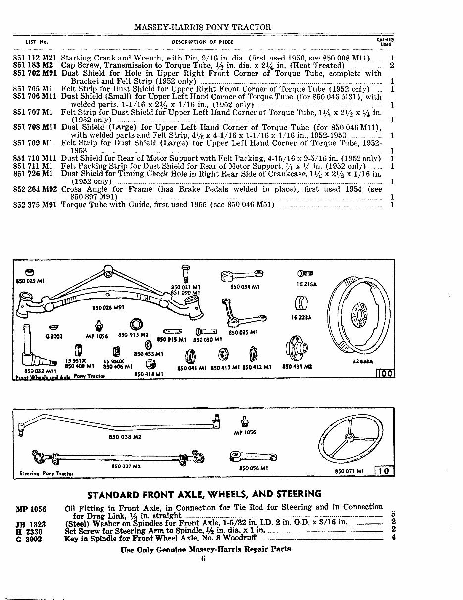
MASSEY-HARRIS PONY TRACTOR .... tltJ LIST No. DESCRIPTIOH Of PIECE Usd 10 936X 15950X 15951X 16216 A 16223A 32833 A 332,(9 A 33250A Steel Washer on Pivot Pin for Front Axle, 13/16 in. I.D., 1% in. O.D. x 1/16 in. (1947-1951) ___________________ _______________ _____________________________________ ___________________________________ 1 Bearing Cone for Hub of Front Wheel (inner) (Timken No. 15590) 2 Cup for Bearing of Front Wheel (inner) (Timken No. 15520) ________________________ 2 Bolt for Rim to Front Wheel Hub, lAa in. dia. x % in. Hex. Hd. _________ 10 Cap for Hub of Front Wheel 2 Disc and Rim for Front Wheel ______________________ _____ 2 (Rubber) Tire for }i'ront Wheel, 4.00-16, 3 Rib, 4 Ply 2 (Rubber) Tube for Front Wheel Tire, 4.00-15 _ ____________ 2 200191 Ml Oil Fitting in Drag .L.lnK and Steering Connection, straight 14-28 Taper Thread (1947 oniy) _____ ______ _____ ___ ___________ ______ ______ ___________________ ____ ____________ ______________________ ___ 4 850 026 M91 Front Axle, with welded parts and 4-850 029 M1, 1-850 031 M1 __________ 1 850029 M1 Bushing in Front Axle, IVa in. lD., 1% in. O.D. x 1¥S in. (Oilite A 13(6) _______ , 850030 M1 Pivot Pin for Front Axle, :n in. dia., 31;4, in. under Cotter (1947-1948. use 850915 M2) 1 850 031 M1 Pivot Pin for Radius Rod, %. in. dia., 2¥2 in. under Hex. Head, o/s in. Fine Thread, up to Serial P.G.A. 14213 (see 851090 M1) _ _ ____________________________________________________________________ 1 850 032 Mil Spindle Axle for Front Wheel, with welded parts, Spindle llh in. dia., Axle 0/8 in. fine 850034 Ml 850035 M1 850036Ml 850037 M2 850038 M2 8500,(1 M1 850055 Ml 850056 M1 850071 M1 850405 M1 850408 Ml 850417 Ml 850418 Ml 850431 M2 850432 M1 850433 Ml 850 915M2 851 090 M1 thread _________________________________._________._________________________________ 2 Steering Arm for Front Wheel (right), llh in. bore __________________________________ ._____________ 1 Steering Arm for Front Wheel (left), IVa in bore ________________________________________________________ 1 Thrust Bearing for Spindle and Axle for Front Wheels (Timken T 113) ___________ 2 Tie Rod for Steering, complete _______________________________________________________________________________ 1 Steering Rod or Drag Link, complete, 3,4 in. dia. x 44 in. centres ____________________________________ 1 Dirt Deftector for Front Wheels, 2%, in. O.D. x 1/16 in. x 2" I.D. ________________ 2 Steering Gear Unit (Ross Gear and Tool S 13093) _______________________________________________________ 1 Arm on Steering Gear for Steering Rod, 90/8 in. long, tapered holes ___________________________________ 1 Steering Wheel, 14 in. dia. ____________________________________________________ 1 Bearing Cone for Hub of Front Wheel (outer) (Timken No. 17580) _____ 2 Cup for Bearing of Front Wheel (outer) (Timken No. 17520) __________________________ 2 Felt Washer in Hub of Front Wheel, 1¥2 in. I.D. x 5/16 in. x 2-8/16 in. O.D. ___________ 2 (Slotted) Nut on Spindle of Front Wheel, o/s in. thread ______________________________________________ 2 Hub for Front Wheel (cast), uses 850405 M1, 15,950 X, 15951 X, 850408 ML__________ 2 Retainer for Felt Washer in Hub of Front Wheel, 1% in. bore x 20/8 in. O.D. ____________ 2 (Steel) Washer for Front Wheel Axle, % in. I.D. x Va in. x 11/2 in. O.D. (7/64 in. slots) ___ 2 Pivot Pin, % in. dia. x 4-1/16 in., 3-19/32 in. centre of holes (first used 1949, will repair 850 030 M1) ______________________________________________________----------------------------------------------------------------------- 1 Pivot Pin for Radius Rod, %, in. dia., 3% in. under Hex. Head, % in. Thread, Serial P.G.A. 14213 up (see 850 031 M1) ____________________________________________________ 1 NOTE-The word "Welded" means the part so described is WELDED to some other part or parts, and should be ordered only as needed. 7 .. . - ..-/-
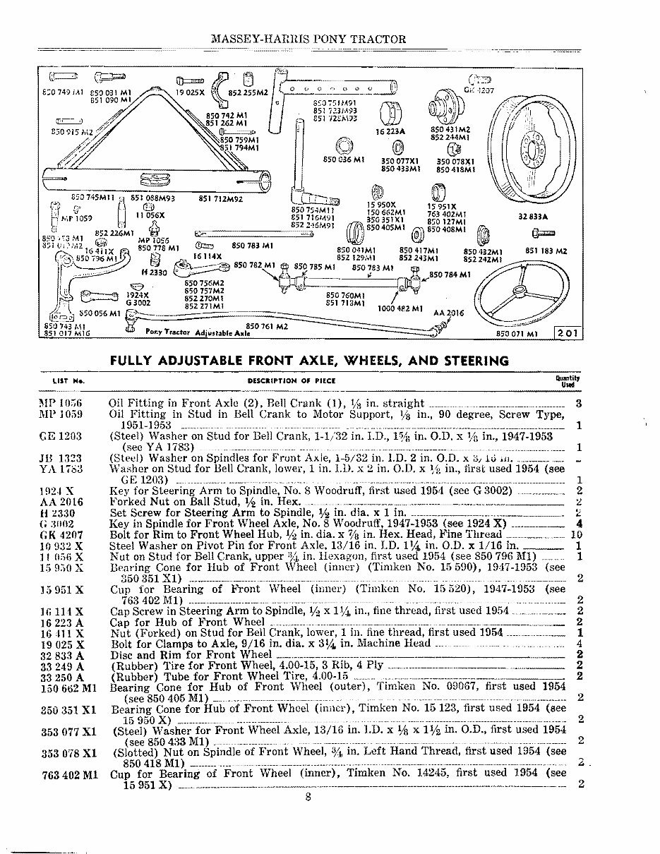
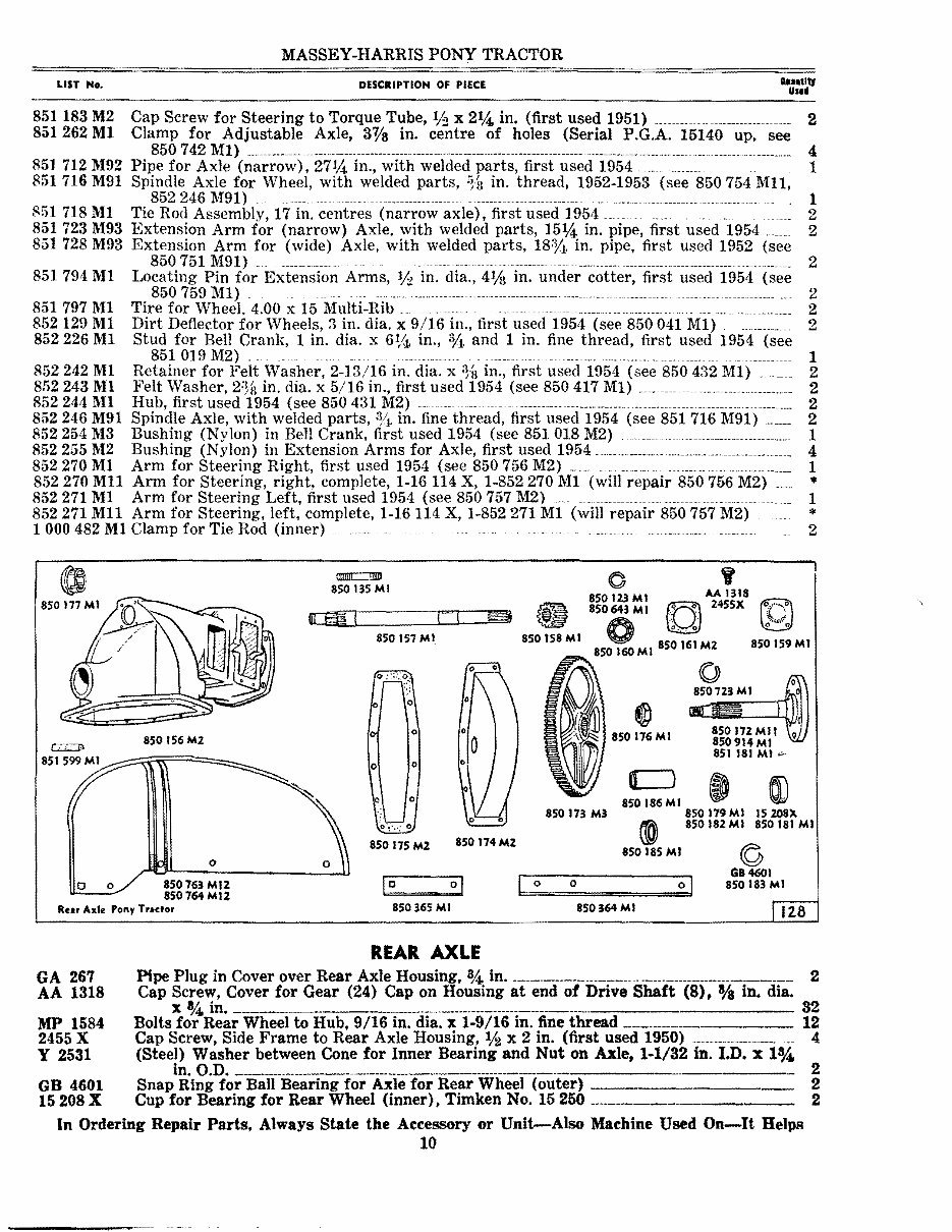
rn== J? [j 1902.5X 850742 Ml 851262 Ml Ol:::===:::r> 8;0749 i.A 1 '850 759Ml 51 794MI MASSEY-HARRIS PONY TRACTOR 0 - • lJi) J j 16 2l3A 6\\ 850036 M I 350077Xl 350078Xl 850 433Ml 850418MI .. 851 712M92 8::0745MII 851088M93 m Ell G' tL'O 8 15950X 15951X t· TJ u 50 754M 11 150 662.M I 763 402M I 31833A b ,.,;r IDS!) ,,11 056X 8517161,0\91 350351)(1 850127MI MPtS6 a]JJB50405MI@)850408MlfrtA 85212.%\1 852243Ml 851183 Ml 850785 M 1 850783 M1 __ " 850 760MI 851713Ml 851 <] 17 M 16 POI'lY Tractor Adjustable Axle 850071 MI 85077SMI ()):zm:, 8:.0 783 MI 8S0041Ml 850417MI G0\ !l50 796MI fi? 'C-''- ;;g 850 782 M 1 H I.r' . e 2330 0 756M2 1924X / l . G3002 852271MI 850 056 M1 SSt) 743 MI. 850 761 M2 J FULLY ADJUSTABLE FRONT AXLE, WHEELS, AND STEERING LIST Ho. DESCIlIPTIOH OF PIECE MP 10;;;6 1\1P 1 GE 1203 JB 1323 YA 1783 ] !'l2-t X AA 2016 H 2330 G :U1I12 GK 4207 10932 X 11 ():"}() X 15950 X ]5951 X It'i1l4X 16223 A 16411 X 19025 X 32833 A 33249 A 33250 A 150662 Ml 350351 Xl 353077 Xl 353078 Xl 763402 Ml Oil Fitting in Front Axie (2), Bell Crank (1), Va in. straight ______ .____ . _______________________ .. ________ Oil Fitting in Stud in Bell Crank to Motor Support, in., 90 degree, Screw Type, 1951-1953 _________ ...... .--...... ___ ___ ._.., ...... _____________________________________________.. ______________ (Steel) Washer on Stud for Bell Crank, 1-1/32 in. LD., 1%: in. O.D. x % in., 1947-1953 (see Y A 1783) . _____ . __ ._______ . _______________________________ .__________________________ (Steel) Washer on Spindles for Front Axle, 1-5;32 in. l.D. 2 in. O.D. x ;:>/ hi w. Washer on Stud for Bell Crank, lower, 1 in. LD. x 2 in. O.D. x in., first used 1954 (see GE 1203) __... _______________.___ .. _____ ...... __ .. _._. . Key for Steering Arm to Spindle, No.8 Woodruff, first used 1954 (see G 3002) Forked Nut on Ball Stud, V2 in. Hex. ----.----.-.- _____ _______ Set Screw for Steering Arm to Spindle, % in. dia. x 1 in. ____ .____________________ .____________ Key in Spindle for Front Wheel Axle, No.8 Woodruff, 1947-1953 (see 1924 X) ____________ Bolt for Rim to Front Wheel Hub. % in. dia. x % in. Hex. Head, Fine Thread Steel Washer on Pivot Pin for Front Axle. 13/16 in. J.D. 1 in. O.D. x 1/16 in. Nut on Stud for Bell Crank, upper in. Hexagon. fi.rst used 1954 (see 850796 M1) Bearing Cone for Hub of Front Wheel (inner) (Timken No. 15590), 19 1 17-1953 350351 Xl) ______________ . _______ ._.. _______ . _____.____ .. _.___ -- .. ----- Cup for Bearing of Front Wheel (inner) (Timken No. 15520), 1947-H153 763 402 lv'Il) ______ .. _______ .____________ .. ____________ .____ . ________________ .. -.--- .... - ...-.. -.-.,-.---- ........ -.. Cap Screw in Steering Arm to Spindle, % x 1%, in., fine thread, first used 1954 Cap for Hub of Front Wheel _ .. _________________________ ... _ .. ___.. ___. _______ .___._ _______________ Nut (Forked) on Stud for Bell Crank, lower, 1 in. fine thread, first used 1954 Bolt for Clamps to Axle, 9/16 in. dia. x SY;a. in. Machine Head ___ .. __ . Disc and Rim for Front Wheel _____ ._. ___________________ .__________ (Rubber) Tire for Front Wheel, 4.00-15, 3 Rib, 4 Ply ___________________ (Rubber) Tube for Front Wheel Tire, 4.00-15 _______ ._ ... ___ .______________________ Bearing Cone for Hub of Front Wheel (outer), Timken No. 09067, first used 1954 (see 850 405 M1) -- - -------- .. --- .. ----.--------------- Bearing Cone for Hub of Front Wheel (inner), Timken No. 15 123, first used 1954 (see 15 950 X) __.__________.... ___ . ______. __________ ...... ----- .....- .... -. .--------.----. (Steel) Washer for Front Wheel Axle, 13/16 in. LD. x Va x 1% in. O.D., first used 1954 (see 850 433 M1) --- .----------.----. (Slotted) Nut on Spindle of Front Wheel, 3/4, in. Left Hand Thread, first used 1954 (see 850 418 M1) ______.. - _____________________________ ._.. ______________..... ___ .. __ --... Cup for Bearing of Front \-Vheel (inner), Timlcen No. 14245, first used 1954 (see 15 951 X) ______ .._________________________________.______________------------------------------ 8 (see (see 3 1 1 1 2 2 4 10 1 1 2 2 2 2 1 4 2 2 2 2 2 2 2 .. 2
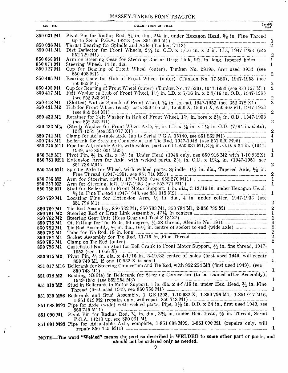
MASSEY-HARRIS PONY TRACTOR c.uanlity LIST No. Di.SCRiP'rlON Or- PICCE Usad 850031 Ml Pivot Pin for Radius Rod, 1ft. in. diu., 2% in. under Hexagon Head, % in. Fine Thread up to Serial P.G .A. 14213 (see 851 O!}O l\I] ) ____ . ______.. _______________.._______________________n ______ .__ _ 1 ____ • 8500361\U Thrust Bearing for Spindle and Axle (Timken T1l3) _____________ ____. ___ .. ____ .. __ ._._________ 2 850041l\I1 Dirt Deflector for Front Wheels, 2Yl. in. O.D. x 1/16 in. x 2 in. LD., 1947-1953 (sec 852 129 1\1]) ._______ ._ 2 8500561\11 Arm on Steering Gear for Steering Rod or Drag Link, 9% in. long, tapered holes.__ 1 850071 1\11 Steering Wheel, 14 in. dia. __ . _.. ._._ .. ________ ._... ___ . _________ . _ 1 8501271\11 Cup for Bearing of Front Wheel (outer), Timken No. 09195, first used 1954 (see 850 408 l\'fl) . ______. ___________________________________________ . ____ . 2 8504051\11 Bearing Cone for Hub of 1"roi1t Wheel (outer) (Timken No. 17580), 1947-1953 (see 150 662 lVll )... ___ _ ___ . _ 2 8504081\11 Cup for Bearing of Front Wheel (outer) (Timlcen No. 17 520), 1947-1953 (see 830127 :!VII) 2 8504171\11 Felt Washer in nub of Front Wheel, in. l.D. x 5/16 in. x 2-3/16 in. O.D., 19/17-1953 (see 852 248 lVIl) .. .. .. ___ ....... 2 850418 Ml (Slotted) Nut on Spir:dle of Front Wheel, "Ii: in. thread, 1947-1953 (see 353078 Xl )__ 2 850431 M2 Hub for Fro11t Wheel (cast), uses 850 4051H1, 15950 X, 15951 X, 850408 M1, 1947-1953 (see 852 244 1\11). _._ ... _______________ . _____________ .____ 850432 Ml Retainer for Felt WaE.her in Hub of Front Wheel, in. bore x 2;"ys in. O.D., 1947-1953 (see 852 242 M1) . ____________. _________________________________. _ ... 2 850 433 Wa,sher for Front Wheel Axle, ;-Vi: in. LD. x l/a in. x 1% in. O.D. (7/64 in. slots), 1947-195:1 (see 353 on Xl) .__ ___ _ __ .________ .. _____ .____ 2 850742 M1 Clamp for Adju:;table Axle (up to Serial P.G.A. 15140, see 851262 M1) ___________________..____ 4 8507431\11 Bellcrank for Steering Connection and Tie Rod, 1947-1948 (use 851020 M96) 1 850 7,t5 Mll Pipe for Adjm;table Axle. 'with welded parts and 1-850031 M1, 3Ya in. O.D. x 34 in. (1947- 1949, use 851 0911\193)__. _____ ._______ .____.. ___ . ------- 1 850749 Ml Pivot Pin, 'Vl- in. dia. x :):h in. Under Head (1948 only, use 850915 M2 with 1-10 932X) 1 850751 M91 Extension Arm for Axle, with welded parts, 2'Ya in. O.D. x 1914 in. (1947-1951, see 851 728 M91) ___ ___ ._. ______. _________________________ . ____ _ 2 850 754 Mll Spindle Axle for Wheel, with welded part:;, Spindle, lIls in. dia., Tapered Axle, %1 in. Fine Thread (1947-1951, see 851 716 M9l) __ _________ . __. ____. __________________..____ ________________ 2 850756 M2 Arm for Steering, right, 19,17-1953 (use 852270 Mll) 1 850757 M2 Arm for Steering. left, ID17-1953 (use 8522711\111)__ ______ .__________________ 1 ( 850758 Ml Stud for Bellcrank to Front Motor Support, 1 in. dia., 3-13/16 in. under Hexagon % in. Fine Thread (1947-1948. see 851 019 M2) _._. ____________ . _______ ._. ________ . _ 1 850759 Ml Locating Pins for Extension Arm, % in. dia., 4 in. under cotter, 1947-1953 (see 851 794 M1) __________ ._____ _ - ____ ._.. ____________. ______ .... ______________________ . ________________________ . _________ . 2 850760 Ml Tie Rod Assembly, 850782 M1, 850783 M1, 850784 Ml, 2.850785 Ml ________.__ 2 Steering Rod or Drag Link Assembly. 47% in centres ___" ____. _____.__._____ 1 850761 M2 Steering Gear Unit (Ross Gear and Tool S 13127) -----._________________________________________ 1 850762 M2 Oil Fitting for Tie Rods, 90 degree, %-28 thread, Alemite No. 1911 ____________________________ 4 850778 Ml 850782 Ml Tie Rod Assembly, ry;; in. dia., 16 1 /:! in. centre of socket to end (wide axle) . ___________________ . 2 Tube for Tie Rod, 18 in. long _____ . ______.____________ _ ___._ 2 850783 Ml Socket Assembly for Tie Rod, 11/16 in. Fine Thread _____ .______________. __ . 2 850784 1'tf1 850785 Ml Clamp on Tie Rod (outer) _----- __ -- -.-------------------------------.---.---------.--------.----------------- 2 850796 Ml Castellated Nut on Stud for Bell Crank to Front Motor Support, o/t. in. fine thread, 1947- 1953 (see 11 056 X) 1 850915 M2 Pivot Pin, % in. dia. x 4-1116 in., 3-19/32 centre of holes (first used 1949, will repair 850 749 M1 if one 10 932 X is sent) ._____________________________________________ .__________ .______ 1 851017 M16 Bellcrank for Steering Connection and Tie Rod, with 852254 M3 (first used 1949), (see 850 743 1\1£ 1) _______ ___ _. ___ . _. - .---- --- ---. ---- .. - -- -- ------ ---- --.----- ---------------------------------- ----- .. ------- .-------- -.. - 1 851018 M2 Bushing (Oilite) in Bel1crank for Steering Connection (to be reamed after Assembly), 1949-1953 (see 852 254 M3 )--_____________________________________________ 1 851019 M2 Stud in Bellcrank to Motor Support. 1 in. dia. x 4-9/16 in. under Hex. Head, %, in. Fine Thread (first used 1949, see 850758 M1) ______________________ . __ ._________________________________________.___ 1 851 020 M96 Bellcrank and Stud Assembly, 1 GE 1203, 1-10932 X, 1-850796 M1, 1-851 017 MIG. 1-851019 M2 (repairs only, will repair 850 743 M1) ----- 851088 M93 Pipe for Axle (wide) with welded parts, Pipe, 3% in. O.D. x 34 in., first used 1949, see 850 745 MIl) __________ . ____ .__________ -------- -------. -------------- ----------------.-------------------------------------- .. -- 1 851 0901\11 Pivot Pin for Radius Rod, in. dia., 3% in. under Hex. Head, IVa in. Thread, Serial P.G .A. 14213 up. see 850 031 M1 ___________ ---------------------.-----.----------------------------------------------- 1 851091 M93 Pipe for Adjustable Axle, complete, 1-851088 M92, 1-851090 Ml (repairs only, will repair 850 745 M11) ___________________________________ ---------------- 1 ( NOTE-The word ''Welded'' means the part so described is WELDED to some other part or parts, and ahould not be ordered only as needed. 9
1947-1954 Massey-Harris Pony Tractor Parts Catalog
The 1947-1954 Massey-Harris Pony Tractor Parts Catalog is the official, factory-issued illustrated parts list used by dealers and mechanics to identify and order every component for the Pony Tractor. Published in 1954, this document is the definitive and final master parts list, canceling all previously issued lists for this model.
This is not a step-by-step repair manual; it is an essential tool for any serious restoration or repair project. For a vintage machine like the Pony Tractor, where parts changed based on serial numbers and production years, this catalog is the only source of truth. It provides the detailed exploded-view diagrams and original part numbers needed to identify the exact bolt, gasket, bearing, or casting required to keep your tractor authentic and operational.
What’s Inside the Massey-Harris Pony Tractor Parts Catalog
Detailed Exploded-View Diagrams & Part Lists
Every assembly on the tractor is illustrated with clear, exploded diagrams. Each component is numbered and cross-referenced to comprehensive lists that provide the official part number, description, and quantity used, allowing for positive identification of every piece of hardware.
Engine and Accessories
Complete parts breakdown for the Continental N62 engine (N62-20, N62E20, and N62F20 models). This includes the cylinder head, crankcase, crankshaft, pistons, camshaft, and all accessories such as the carburetor, air cleaner, governor, starting motor, and generator.
Transmission, Drivetrain & Power Take-Off
Full parts identification for the clutch, transmission housing, gears, shifter mechanism, differential, and rear axle. It also includes detailed diagrams for the complete Power Take-Off (PTO) and pulley attachment assemblies.
Chassis, Steering, and Axles
Covers all frame and chassis components, including the torque tube and drawbar attachment. It provides separate, detailed parts lists for both the Standard Front Axle and the Fully Adjustable Front Axle, as well as the complete steering system.
Wheels, Brakes & Hydraulics
Includes parts for all wheel configurations (front, rear, and market garden wheels), brake assemblies, and the complete hydraulic lift system, from the pump and valve to the cylinder and linkage.
Numerical Index for Easy Cross-Referencing
A comprehensive numerical index at the end of the manual allows you to quickly find the location of any part number, making it easy to cross-reference components and identify their application within the tractor's assemblies.
Why Choose This Official Massey-Harris Parts Catalog?
For anyone restoring a Massey-Harris Pony, this document is indispensable. Unlike generic lists, it details the specific parts used based on tractor and engine serial numbers—critical information for sourcing correct, period-accurate components. It is the factory's own guide to the machine's construction, ensuring total authenticity for your project.
Format & Compatibility
This parts catalog is delivered as a high-resolution, fully searchable PDF that is compatible with all devices, including Windows, macOS, Linux, iOS, and Android. Use it on a computer for detailed viewing or print the pages you need to take with you to the workshop.
Start Your Restoration with Confidence
Stop searching and guessing. With this official parts catalog, you have the definitive factory resource to identify every part on your 1947-1954 Massey-Harris Pony Tractor with absolute certainty. Download now and get the accuracy you need for a professional-quality restoration.
Printable: Yes Language: English Compatibility: Works on all devices (Windows, Mac, iOS, Android) Requirements: PDF reader (e.g. Adobe Reader)
Recently Viewed
5,521,897Happy Clients
2,594,462eManuals
1,120,453Trusted Sellers
15Years in Business
Price:
Actual Price:
1947-1954 Massey-Harris Pony Tractor Parts Catalog