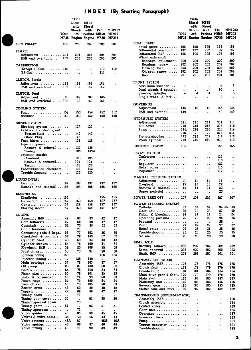
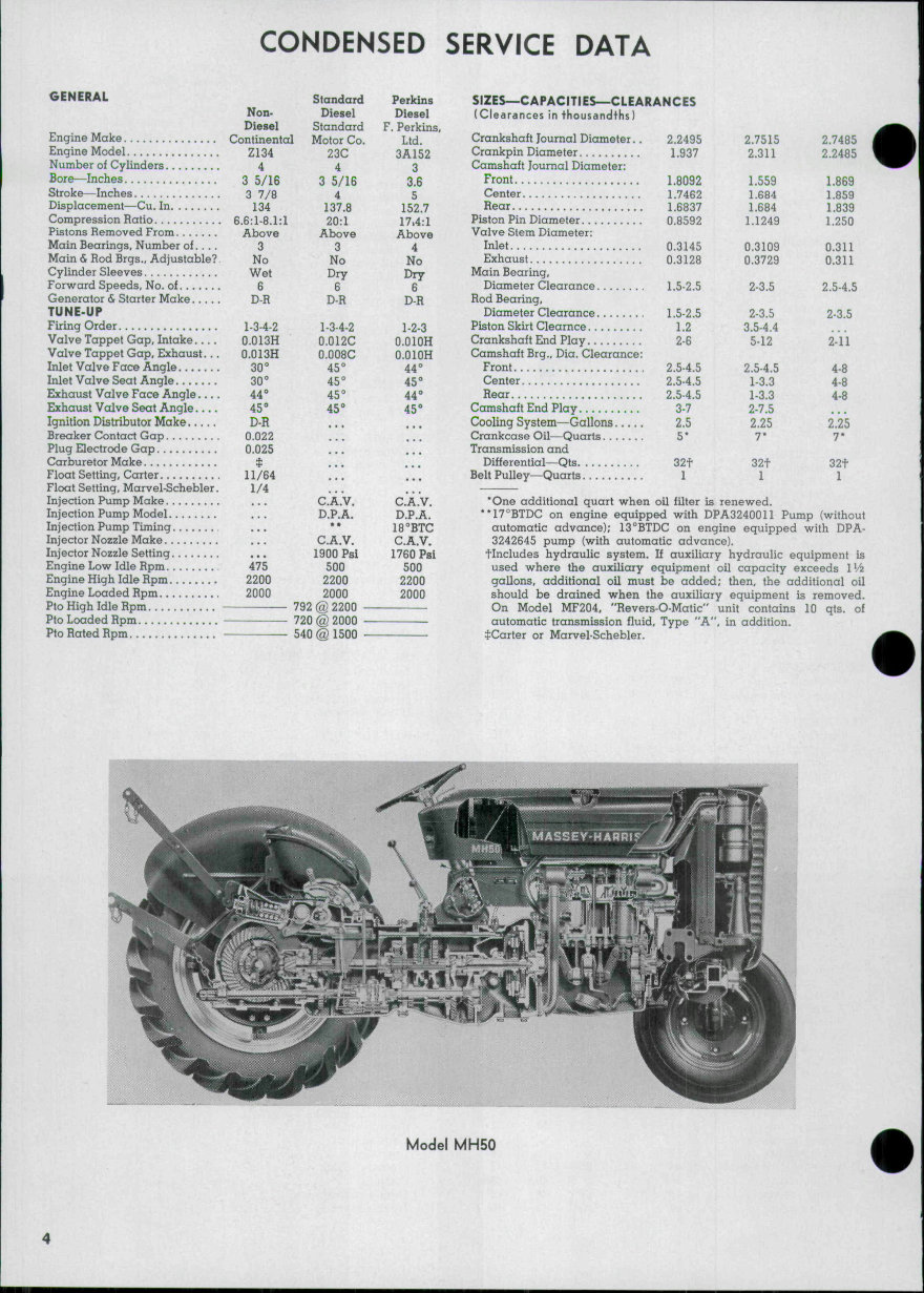
CONDENSED SERVICE DATA GENERAL Engine Make Engine Model Number of Cylinders Bore—Inches Stroke—Inches Displacement—Cu. In Compression Ratio Pistons Removed From Main Bearings, Number of .... Main & Rod Brgs., Adjustable? Cylinder Sleeves Forward Speeds, No. of Generator & Starter Make TUNE-UP Firing Order Valve Tappet Gap, Intake .... Valve Tappet Gap, Exhaust... Inlet Valve Face Angle Inlet Valve Seat Angle Exhaust Valve Face Angle .... Exhaust Valve Seat Angle .... Ignition Distributor Make Breaker Contact Gap Plug Electrode Gap Carburetor Make Float Setting, Carter Float Setting, Marvel-Schebler. Injection Pump Make Injection Pump Model Injection Pump Timing Injector Nozzle Make Injector Nozzle Setting Engine Low Idle Rpm Engine High Idle Rpm Engine Loaded Rpm Pto High Idle Rpm Pto Loaded Rpm Pto Rated Hpm Non- Diesel Continental Z134 4 3 5/16 3 7/8 134 6.6:1-8.1:1 Above 3 No Wet 6 D-R 1-3-4-2 0.013H 0.013H 30° 30° 44° 45° Standard Diesel Standard Motor Co. 23C 4 3 5/16 4 137.8 20:1 Above 3 No Dry 6 D-H 1-3-4-2 0.012C 0.008C 45° 45° 45° 45° Perkins Diesel F. Perkins Ltd. 3A152 3 3.6 5 152.7 17.4:1 Above 4 No Dry 6 D-R 1-2-3 O.OIOH O.OIOH 44° 45° 44° 45° D-R 0.022 0.025 t 11/64 1/4 475 2200 2000 C.A.V. D.P.A. • * C.A.V. 1900 Psi 500 2200 2000 792 @ 2200 720 @ 2000 540 @ 1500 C.A.V. D.P.A. 18°BTC C.A.V. 1780 Pai 500 2200 2000 SIZES—CAPACITIES—CLEARANCES (Clearances In thousandths) Crankshaft Journal Diameter.. 2.2495 2.7515 2,7485 Crankpin Diameter 1.937 2.311 2.2485 Camshaft Journal Diameter: Front 1,8092 1.559 1.869 Center 1.7462 1.684 1.859 Rear 1.6837 1.684 1.839 Piston Pin Diameter 0.8592 1.1249 1.250 Valve Stem Diameter: Inlet 0.3145 0.3109 0.311 Exhaust 0.3128 0.3729 0.311 Main Bearing, Diameter Clearance 1.5-2.5 2-3.5 2.5-4.5 Rod Bearing, Diameter Clearance 1.5-2.5 2-3.5 2-3.5 Piston Skirt Clearnce 1.2 3.5-4.4 Crankshaft End Play 2-6 5-12 2-11 Camshaft Brg., Dia. Clearance: Front 2.5-4.5 2.5-4.5 4-8 Center 2.5-4.5 1-3.3 4-8 Rear 2.5-4.5 1-3.3 4-8 Camshaft End Play 3-7 2-7.5 Cooling System—Gallons 2.5 2.25 2.25 Crankcase Oil—Quarts 5* 7* 7* Transmission and Differential—Qts 32t 32t 32t Belt Pulley—Quarts 1 1 1 "One additional quart when oil filter is renewed. **17°BTDC on engine equipped with DPA3240011 Pump (without automatic advance); 13°BTDC on engine equipped with DPA- 3242645 pump (with automatic advance). tincludes hydraulic system. If auxiliary hydraulic equipment is used where the auxiliary equipment oil capacity exceeds l'/2 gallons, additional oil must be added; then, the additional oil should be drained when the auxiliary equipment is removed. On Model MF204, "Revers-O-Matic" unit contains 10 qts. of automatic transmission fluid. Type "A", in addition. :i:Carter or Marvel-Schebler. Model MH50
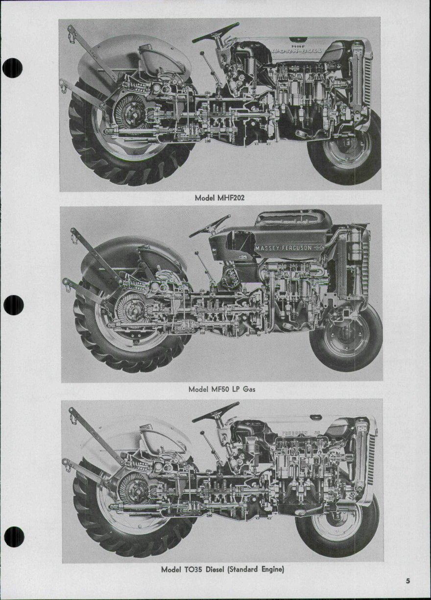
Model MHF202 Model MF50 LP Gas Model TO35 Diesel (Standard Engine)
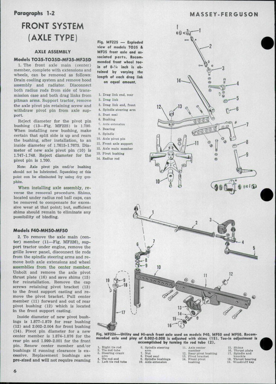
Paragraphs 1-2 FRONT SYSTEM (AXLE TYPE) AXLE ASSEMBLY Models TO35-TO35D-MF35-MF35D 1. The front axle main (center) member, complete with extensions and wheels, can be removed as follows: Drain cooling system and remove hood assembly and radiator. Disconnect both radius rods from side of trans- mission case and both drag links from pitman arms. Support tractor, remove the axle pivot pin retaining screw and withdraw pivot pin from axle sup- port. Reject diameter for the pivot pin bushing (13—Fig. MF225) is 1.790. When installing new bushing, make certain that split side is up and ream the bushing, after installation, to an inside diameter of 1.7615-1.7675. Dia- meter of new axle pivot pin (10) is 1.747-1.748. Reject diameter for the pivot pin is 1.700. Note: Axle pivot pin and/or bushing should not be lubricated. Squeaking at this point can be eliminated by using dry gra- phite. When installing axle assembly, re- verse the removal procedure. Shims, located under radius rod ball caps, can be removed to compensate for exces- sive wear at that point; but, sufficient shims should remain to eliminate any possibility of binding. Models F40-MH50-MF50 2. To remove the axle main (cen- ter) member (11—Fig. MF226), sup- port tractor under engine, remove the grille lower panel, disconnect tie rods from the spindle steering arms and re- move both axle extensions and wheel assemblies from the center member. Unbolt and remove the axle pivot thrust plate (16) and save shims (15) for reinstallation. Remove the cap screws retaining pivot bracket (13) to the front support casting and re- move the pivot bracket. Pull center member (11) forward and out of rear pivot bushing (12) which is located in the front support casting. Inside diameter of new pivot bush- ings is 1.877-1.879 for rear bushing (12) and 2.002-2.004 for front bushing (14). Pivot pin diameter for a new center member is 1.874-1.876 for the rear pin and 1.999-2.001 for the front pin. Renew center member and/or bushings if running clearance is ex- cessive. Replacement bushings are pre-8ized and will not require reaming MASSEY-FERGUSON Fig. MF225 — Exploded view of models TO35 & MF35 front axle and as- sociated parts. Recom- mended front wheel toe- in of O-V4 inch is ob- tained by varying the length of each drag link on equal amount. 1. 2. 3. 4. 6. 6. 7_ 8. 9. 10. 11. 12. 13. 14. Drag hnk end, rear Drag link Drag link end, front Spindle steering arm Dust Beal Bushing Axle extension Bearing Spindle Axle pivot pin Front axle support Axle main member Pivot bushing Radius rod 10 19 Fig. MF226—Utility and Hi-arch front axle used on models F40, MF50 and MF50. Recom- mended axle end play of 0.002-0.008 is adjusted with shims (15). Toe-in adjustment if accomplished by turning tie rod tube ( 2 ) . 1. Right tie rod 2. Tie rod tube 3. Steering crank arm 4. Tie rod end 5. Left tie rod tube 6. Spindle steering arm 7. Nut 8. Dust seal 9. Spindle bushings 10. Axle extension 11. Axle center member 12. Rear pivot bushing 13. Pivot bracket 14. Front pivot bushing 15. Shims 16. Thrust plate 17. Spindle and knuckle 18. Thrust bearing 19. Woodruff key
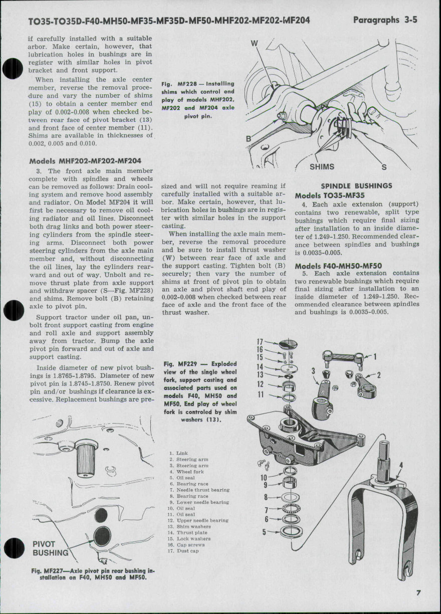
TO35-TO35D-F40<MH50-MF35-MF35D-MF50-MHF202'MF202-MF204 Paragraphs 3-5 if carefully installed with a suitable arbor. Make certain, however, that lubrication holes in bushings are in register with similar holes in pivot bracket and front support. When installing the axle center member, reverse the removal proce- dure and vary the number of shims (15) to obtain a center member end play of 0.002-0.008 when checked be- tween rear face of pivot bracket (13) and front face of center member (11). Shims are available in thicknesses of 0.002, 0.005 and 0.010. Moders MHF202-MF202-MF204 3. The front axle main member complete with spindles and wheels can be removed as follows: Drain cool- ing system and remove hood assembly and radiator. On Model MF204 it will first be necessary to remove oil cool- ing radiator and oil lines. Disconnect both drag links and both power steer- ing cylinders from the spindle steer- ing arms. Disconnect both power steering cylinders from the axle main member and, without disconnecting the oil lines, lay the cylinders rear- w ard and out of way. Unbolt and re- move thrust plate from axle support and withdraw spacer (S—Fig. MF228) and shims. Remove bolt (B) retaining axle to pivot pin. Support tractor under oil pan, un- bolt front support casting from engine and roll axle and support assembly away from tractor. Bump the axle pivot pin forward and out of axle and support casting. Inside diameter of new pivot bush- ings is 1.8765-1.8795. Diameter of new pivot pin is 1.8745-1.8750. Renew pivot pin and/or bushings if clearance is ex- cessive. Replacement bushings are pre- w Fig. MF228 — Installing shims which control end play of models MHF202. MF202 and MF204 axle pivot pin. sized and will not require reaming if carefully installed with a suitable ar- bor. Make certain, however, that lu- brication holes in bushings are in regis- ter with similar holes in the support casting. When installing the axle main mem- ber, reverse the removal procedure and be sure to install thrust washer (W) between rear face of axle and the support casting. Tighten bolt (B) securely; then vary the number of shims at front of pivot pin to obtain an axle and pivot shaft end play of 0.002-0.008 when checked between rear face of axle and the front face of the thrust washer. SPINDLE BUSHINGS Models TO35-MF35 4. Each axle extension (support) contains two renewable, split type bushings which require final sizing after installation to an inside diame- ter of 1.249-1.250. Recommended clear- ance between spindles and bushings is 0.0035-0.005. Models F40-MH50-MF50 5. Each axle extension contains two renewable bushings which require final sizing after installation to an inside diameter of 1.249-1.250. Rec- ommended clearance between spindles and bushings is 0.0035-0.005. Fig. MF229 — Exploded view of the single wheel fork, support casting and associated parts used on models F40, MH50 and MF50. End play of wheel foric is controled by shim washers (13). 1. 2. 3. 4. 5, 6. 7. 8. 9. 10. 11. 12. 13. 14. 15. 16. 17. Link Steering arm Steering arm Wheel fork Oil seal Bearing race Needle thrust bearing Bearing race Lower needle bearing Oil seal Oil seal Upper needle bearing Shim washers Thrust plate Lock washers Cap screws Dust cap Fig. MF227—Axle pivot pin rear bushing in- stallation on F40. MH50 and MF50.
Paragraphs 6-11 MASSEY'FERGUSON Models MHF202-MF202-MF204 6. Each end of the front axle main member contains two renewable bush- ings which require final sizing after installation to an inside diameter of 1.499-1.500. Recommended clearance between spindles and bushings is 0.0035-0.005. TOE-IN, TIE-RODS AND/OR DRAG LINKS Models TO35-MF35 MHF202-MF202-MF204 7. Each drag link is fitted with two non-adjustable, automotive type drag link ends. Recommended toe-in of 0-y4 inch is adjusted by varying the length of each drag link an equal amount. Models F40-MH50-MF50 8. Tie-rod ends are of the non- adjustable, automotive type. Recommended toe-in of O-Vi inch is adjusted by varying the length of the right hand tie rod. This is accomp- lished by loosening the tube set screw and clamp bolt and turning the tube (2—Fig. MF226) either way as re- quired. Be sure the tube set screw is in the forward position before tight- ening. Center to center distance be- tween drag link ends is 49% inches. FRONT SYSTEM (Tricycle Type) SINGLE WHEEL & FORK Models F40-MH50-MF50 9. The fork mounted single front wheel is carried in taper roller bear- ings which should be adjusted to pro- vide a very slight rotational drag. To remove the wheel fork, support tractor under engine and remove the grille lower panel. Open the grille door and remove the sheet metal dust cap (17—Fig. MF229). Remove the cap screws (16) retaining thrust plate (14) to upper end of wheel fork and with- draw thrust plate (14) and shim wash- ers (13). Working through opening in the support casting, loosen the clamp bolt retaining steering arm (3) to wheel fork. Raise front of tractor and at the same time, withdraw the wheel fork from below. CAUTION: Wheel fork must not be cocked during re- moval or seals and needle bearings may be damaged. Examine needle bearings (9 and 12), seals (5, 10 and 11) and needle thrust bearing (6, 7 and 8) and renew any questionable parts. When installing the caged needle bearings (9 and 12), be sure to align the oil hole in the bear- ings with the oil feed holes in the sup- port casting. Install the wheel fork by reversing the removal procedure and vary the number of shim washers (13) to pro- vide the wheel fork with an up and down end play of 0.002-0.008. Note: The wheel fork and steering arm (3) have a blind spline to facilitate correct in- stallation. DUAL WHEELS, LOWER SPINDLE AND LOWER PEDESTAL Models F40-MH50-MF50 10. Each of the dual wheels is mounted on taper roller bearings which should be adjusted to provide a very slight rotational drag. To remove the lower spindle and wheels assembly, support tractor un- der engine and remove the grille lower panel. Open the grille door, unlock and remove cap screw (16— Fig. MF230), locking washer (15) and flat washer (14). Working through opening in the support casting, loosen the clamp bolt retaining steering arm (13) to the spindle. Raise front of tractor and at the same time, with- draw the spindle, axle and wheels assembly from below. Lower pedestal (6) can be removed from the support casting at this time. Examine bearing cones (4 and 8), cups (5 and 7) and seals (3 and 9) and renew any questionable parts. Install the spindle and lower pedes- tal by reversing the removal proce- dure and tighten cap screw (16) to remove all spindle end play without causing any bearing drag. Note: The lower spindle (12) and steering arm (13) have a blind spline to facilitate correct installation. MANUAL STEERING SYSTEM Models TO35-MF35 11. ADJUSTMENT. Before attempt- ing to adjust the steering gear, first make certain that the gear housing is properly filled with lubricant, then disconnect drag links from pitman arms to remove load from gear unit. Fig. MF230 — Expioded view of the dual wlieei tricycie iower spindie, pedestai and related parts. Spindle bearings siiouid be adjusted to re- move all end play with- out binding. 1. Link 2. Steering urni 3. Oil seal 4. Bearing cone r*. Bearing cup 6. Lower pedestal 7. Bearing cup 8. Bearing cone 9. Oil seal 10. Axle 12. Lower spindle !3. Steering arm 14. Washer 15. Locking wa8hei 16. Cap screw 8
TO35-TO35D-F40-MH50-MF35-MF35D-MF50-MHF202-MF202-MF204 Paragraphs 12-15A 12. WORM SHAFT BEARINGS. To check and/or adjust the steering worm shaft bearings, first loosen the lock nuts and back off the right and left hand sector adjusting screws (31— Fig. MF232) approximately four turns. Attach a spring scale to outer edge of steering wheel and check the amount of pull required to keep the steering wheel in motion after it has crossed the mid or center point of its rotation. The wormshaft bearings are properly pre-loaded when the spring scale reading is Va-l^/^ pounds. If bearing adjustment is not as speci- fied, unbolt steering housing cover from housing and vary the number of shims (26) until the desired bearing pre-load is obtained. Shims are avail- able in thicknesses of 0.002, 0.005, 0.010 and 0.030. 13. SECTOR BACKLASH. With the wormshaft bearings properly adjusted as outlined in paragraph 12, proceed as follows: Turn the steering wheel to the mid (or straight ahead) position (lower ends of Pitman arms over ra- dius rod ball joints) and using a screw driver, turn the adjusting screw for the left hand sector shaft until a spring scale pull of l%-3 pounds (measured at rim of steering wheel) will keep the wheel in motion after it has crossed the mid or center point of its rotation. With the left sector shaft adjusted, turn the adjusting screw for the right sector shaft until a spring scale pull of 3'74-5 pounds (measured at rim of steering wheel) will keep the steering wheel in motion after it has crossed the mid or center point of its rota- tion. 14. REMOVE AND REINSTALL. To remove the steering gear housing, in- strument panel and transmission cov- er assembly, proceed as follows: Tip hood assembly forward, drain cool- ing system and disconnect the heat indicator sending unit from the water outlet elbow. Disconnect cable from starting motor and wires from coil, headlights and generator. Disconnect tractormeter cable from generator, choke rod from carburetor and oil gage line from right side of cylinder block. On Diesel models, disconnect tractormeter cable, fuel shut-off con- trol rod and throttle control rod from injection pump; then disconnect oil pressure banjo fitting at left side of block. Remove air cleaner pipe, shut off fuel and remove fuel line. Unbolt fuel tank from its rear support, loosen the fuel tank front support bolts and block up between the fuel tank and rocker arm cover. Loosen the U-bolt assembly from front end of throttle rod. Disconnect battery cables and remove battery. Disconnect tail light wires and wires from start- er safety switch. Disconnect drag links from pitman arms, unbolt bat- tery platform from engine, unbolt transmission cover from transmission and lift the steering gear and housing assembly from tractor. 15. OVERHAUL. The steering gear unit can be overhauled without re- moving gear housing assembly from tractor by removing the battery and the instrument panel and battery platform assembly as outlined in paragraph 15A. Some mechanics pre- fer to remove the complete gear hous- ing assembly as outlined in paragraph 14 before attempting to disassemble the steering gear. In either case, however, the time involved is about the same. 15A. To remove the instrument pan- el, tip hood assembly forward, drain cooling system and disconnect the heat indicator sending unit from the water outlet elbow. Disconnect cable from starting motor and wires from coil, -headlights and generator. Dis- connect tractormeter cable from gen- erator and choke rod from carburetor. On Diesel models, disconnect tractor- meter cable, fuel shut-off control rod and throttle control rod from injection pump. Remove air cleaner and rubber intake tube and disconnect oil line from gage. Shut off fuel and remove fuel line. Unbolt fuel tank from its rear support, loosen the fuel tank front support bolts and block-up between the fuel tank and the rocker arm cover. Loosen the U-bolt assembly from front end of throttle rod. Dis- connect battery cables and remove battery. Disconnect tail light wires and starter safety switch wires. Re- move the steering wheel nut and using a suitable puller, remove steer- ing wheel from shaft. Remove the steering column felt seal, cap and spring. Unbolt and remove battery platform and instrument panel assem- bly from tractor. Fig. MF231 — Cutaway view of models TO35 and MF35 manual steering gear. The steering gear housing and transmission top cover are an integral unit. The steering gear is provided with a shim ad- justment for the worm- shaft bearings and screw adjustments for backlash of both sectors. Fig. MF232—Models TO35 & MF35 steer- ing gear adjustments. Shims (26) control wormshaft bearing adjustment. Screws (31) control the sector backlash. 19. Steering coiumn & 28. Steering housing housins top cover side cover
Paragraph 16 MASSEY-FERGUSON 16. Disconect drag links from pit- man arms and unbolt and pull pit- man arms from sector shafts. Unbolt the side cover for the upper sector shaft (36—Fig. MF233) and remove lock nut from screw (31). Using a screw driver, turn the adjusting screw in and remove the side cover and sec- tor shaft. Remove the other side cov- er and sector shaft in the same man- ner. Unbolt steering housing upper cover from housing and remove cov- er, shaft and ball nut assembly. Do not disassemble the ball nut assembly (41) as component replacement parts are not available. If the steering shaft and/or ball nut are damaged, renew the complete assembly. The need and procedure for further dis- assembly and/or overhaul is evident. Shims (30) on the adjusting screws (31) are available in thicknesses of 0.063, 0.065, 0.067 and 0.069. When reassembling, use the proper com- bination of shims to provide a very slight amount of clearance between adjusting screw head and slot in sec- tor shafts. When reassembling, install the steering shaft and ball nut assembly and bolt the housing upper cover as- sembly in position, using the neces- sary number of shims (26) to very slightly pre-load the shaft bearings. Turn the steering shaft until the ball nut raises to a position where the lower gear tooth on the ball nut is clearly visible through the right side opening in housing. Hold the lower sector shaft (the one with the great- er number of teeth) and side cover assembly with blank portion of gear down and install shaft through right side opening in housing. Mesh sector gear with ball nut so that lower tooth on ball nut meshes with the groove next to the blank portion of sector shaft gear. Install the upper sector shaft, meshing the double punch marked tooth space on upper sector gear with the single punch marked tooth on the lower sector gear. Bolt side covers to steering gear housing and install the adjusting screw lock- nuts. Turn steering gear to its mid or straight ahead position and install pitman arms (longer one on right side) so that drag link attaching holes are directly above the radius rod ball joints. When installation is complete, fin gear housing with lubricant and ad- just the unit as outlined in para- graphs 11, 12 and 13. 35 Fig. MF233—Exploded view of modeis TO35 & MF35 manuai steering gear. The gear housing is aiso the transmission housing top cover. 12. Nut 13. Felt seal 14. Steering column cap 15. Spring 16. Spring Beat 17. Cap seal 18. Bearing 19. Steering column and housing top cover 20. Roller bearing & cage 21. "O" ring packing 22. Pitman arm nut 23. Pitman arm, right 24. Dust Beal 2b. Oil Beal 26. ShimB 27. Packing 28. HouBing Bide cover 29. "O" ring packing 30. Shim 31. Lash adjUBting Bcrew 32. Sector Bhaft, double 33. 34. Gasket 36. Pitman arm, left 36. Sector Bhaft, Bingle 37. Bearing cup 38. Eyelet 39. Bearing retainer 40. Roller bearing A cage 41. Steering shaft A bail nut aBBembiy 42. Key Fig. MF234 —The model TO35 & MF35 manuol steering geor unit can be overhauled without re- moving the assembly from tractor by removing the instrument panel and bat- tery platform assembly. 10
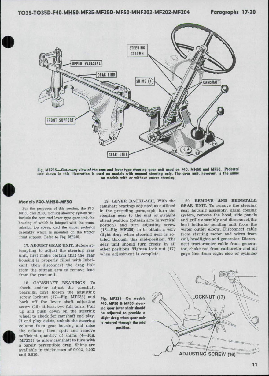
TO35-TO35D-F40-MH50-MF35.MF35D-MF50-MHF202-MF202-MF204 Paragraphs 17-20 UPPER PEDESTAL IDRAG LINK STEERING COLUMN SHIMS \. 0 |CAMSHAFT| W' FRONT SUPPORT Fig. MF235—Cut-away view of the cam and iever type steering gear unit used on F40. MH50 and MF50. Pedestal unit shown in this iilustratlon is used on models with manual steering oniy. The gear unit, however, it the tame on models with or without power steering. Models F40-MH50-MF50 For the purposes of this section, the F40. MH50 and MF50 manual steering system will include the cam and lever type gear unit, the housing oi which is integral with the trans- mission top cover; and the upper pedestal assembly which is mounted on the tractor front support. Refer to Fig. MF235. 17. ADJUST GEAR UNIT. Before at- tempting to adjust the steering gear unit, first make certain that the gear housing is properly filled with lubri- cant, then disconnect the drag link from the pitman arm to remove load from the gear unit. 18. CAMSHAFT BEARINGS. To check and/or adjust the camshaft bearings, first loosen the adjusting screw locknut (17—Fig. MF236) and back off the lever shaft adjusting screw (16) at least two full turns. Pull up and push down on the steering wheel to check for camshaft end play. If end play exists, unbolt the steering column from gear housing and raise the column; then, split and remove sufficient quantity of shims (4—Fig. MF235) to allow camshaft to turn with a barely perceptible drag. Shims are available in thicknesses of 0.002, 0.003 and 0.010. 19. LEVER BACKLASH. With the camshaft bearings adjusted as outlined in the preceding paragraph, turn the steering gear to the mid or straight ahead position (pitman arm in vertical postion) and turn adjusting screw (16—Fig. MF236) in to obtain a very slight drag when steering gear is ro- tated through this mid-position. The gear unit should turn freely in all other positions. Tighten lock nut (17) when adjustment is complete. 20. REMOVE AND REINSTALL GEAR UNIT. To remove the steering gear housing assembly, drain cooling system, remove the hood, side panels and grille assembly and disconnect the heat indicator sending unit from the water outlet elbow. Disconnect cable from starting motor and wires from coil, headlights and generator. Discon- nect tractormeter cable from genera- tor, choke rod from carburetor and oil gage line from right side of cylinder Fig. MF236—On modeis F40. MF50 & MF50. steer- ing gear iever shaft should be adjusted to provide a slight drag when gear unit is rotated through the mid position. ADJUSTING SCREW {^6y 11
Paragraphs 21-22 MASSEY-FERGUSON block. Shut off the fuel and remove the fuel line. Unbolt the fuel tank from its rear support, loosen the fuel tank front support bolts and block up between fuel tank and rocker cover. Note: Some mechanics prefer to com- pletely remove the fuel tank. Loosen the U-bolt assembly from front end of throttle rod. Disconnect battery cables and remove battery. Disconnect tail light wires and wires from starter saf- ety switch. Unbolt battery platform from engine and remove steering wheel, steering wheel Woodruff key, felt washer (25—Fig. MF237), spring (22), chrome cap (24) and rubber seal (23). Remove the cap screws retaining the instrument panel and battery plat- form to steering gear housing and lift the instrument panel and battery plat- form assembly from tractor. 21. Disconnect drag link from pit- man arm, remove the cap screws re- taining the transmission cover to transmission housing and lift the steering gear and transmission cover unit from tractor. 22. OVERHAUL GEAR UNIT. The steering gear unit can be overhauled Fig. MF238—Upper ped- estal and drag linli in- stallation on models F40. MH50 & MF50 equipped with manual steering and adjustable type front axle. The installation on tricycle models is similar except for details of the lower steering arm. without removing the gear housing as- sembly from tractor by removing the instrument panel and battery platform assembly as outlined in paragraph 20. Remove pitman arm from lever shaft, and remove the gear housing side cover (18—Fig. MF237). Withdraw the lever shaft and stud assembly. Ex- amine the stud and renew same if damaged or excessively worn. Note: On axle type tractors, the stud (14A) is mounted in roller bearings, but component parts of the stud assembly are not sold separately. Remove the steering column and gear housing cover (2) and save shims (4) for reinstallation. Withdra\, the camshaft, remove snap rings (5), cups (6) and bearing balls (7). Examine all parts and renew any which are questionable. 16 Fig. MF237—Exploded view of the cam and lever type steering gear unit used on models F40, MH50 and MF50. Camshaft bearings and iever baciclash are adjustabie. 1. Woodruff key 2. Steering column and cover 3. ••C" ring 4. Shims 5. Snap ring (i. Ball cup 7. Bearing balls 8. Cam and shaft assembly 9. Pitman arm 10. Oil seal 11. Bushings 12. Housing 13. Housing plug 14. Lever stud (tricycle 18. Side cover models) 14A. Lever stud (axle models) 13. Lever shaft 16. Adjusting screw 17. Lock nut 19. Gasket 20. Bearing assembiy 21. Bearing spring seat 22. Bearing spring 23. Seal 24. Steering column cap 23. Felt seal New lever shaft bushings (11) should be rean:ied after installation, if necessary, to provide an inside dia- meter of 1.6235-1.625. The lever shaft (15) should have a clearance of 0.0005- 0.003 in the bushings. When reassembling the unit, adjust the camshaft bearings as in paragraph 18 and the lever backlash as in para- graph 19. Fig. MF239—Exploded view of the upper pedestal and components used on models F40, MH50 and MF50 with manual steering. 20. Nut 27. Lock washer 28. Flat washer 29. Upper steering arm 30. Pedestal shaft 31. Dust seals 32. Bushings Xi. Pedestal 3.">. Front support 12
The Massey Ferguson TO35, MF35, F40, MH50, MF50, MHF202, MF202, MF204 Tractor Service & Repair Manual delivers factory procedures for maintenance, diagnostics, and complete mechanical repair of a wide range of classic Ferguson and Massey Ferguson utility tractors. Spanning agricultural and industrial models from the mid-1950s through the early 1960s, this manual is indispensable for restoration projects and serious service work alike.
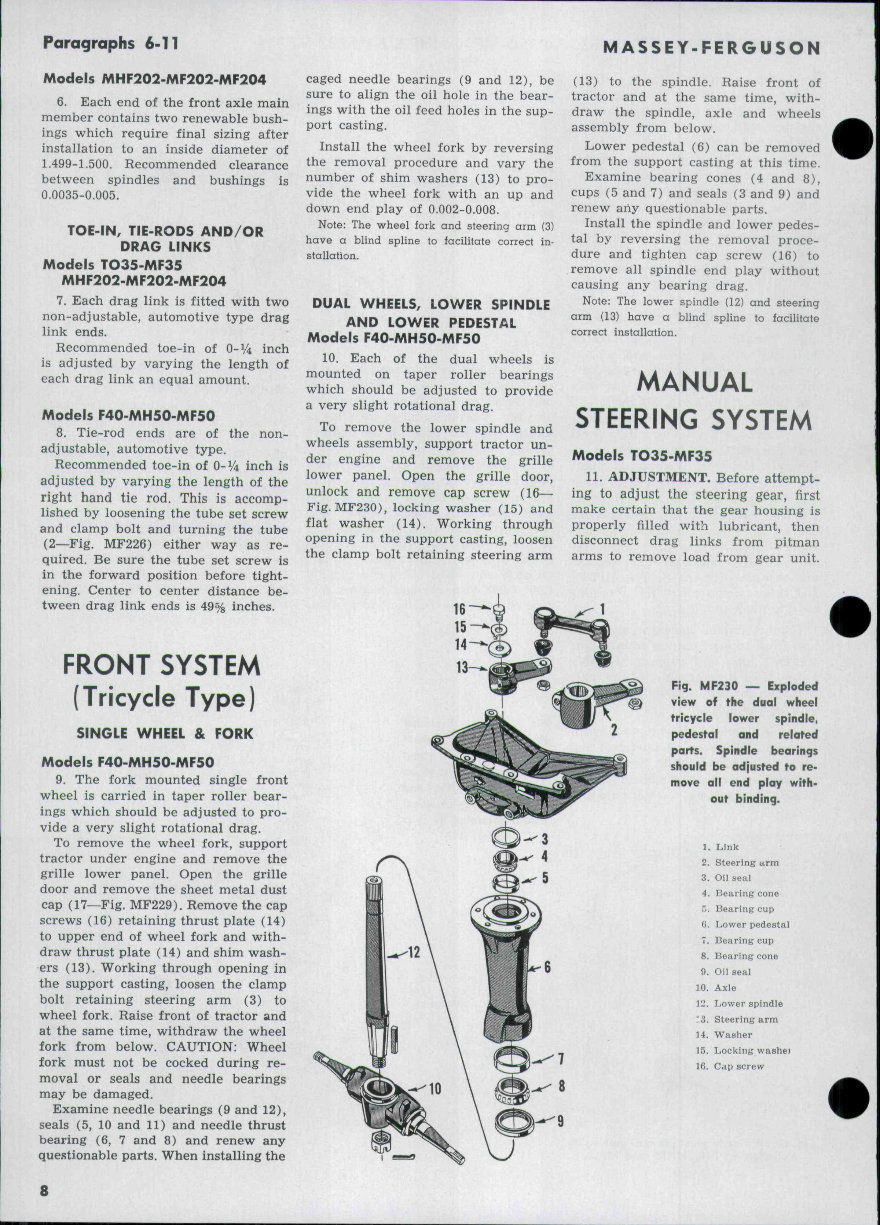
This manual provides comprehensive guidance for tractors equipped with Continental gas engines, Standard and Perkins diesel engines, and LP-Gas variants. With clear step-by-step instructions, factory torque specifications, and exploded-view illustrations, it covers every major system from engine and clutch to hydraulics and PTO.
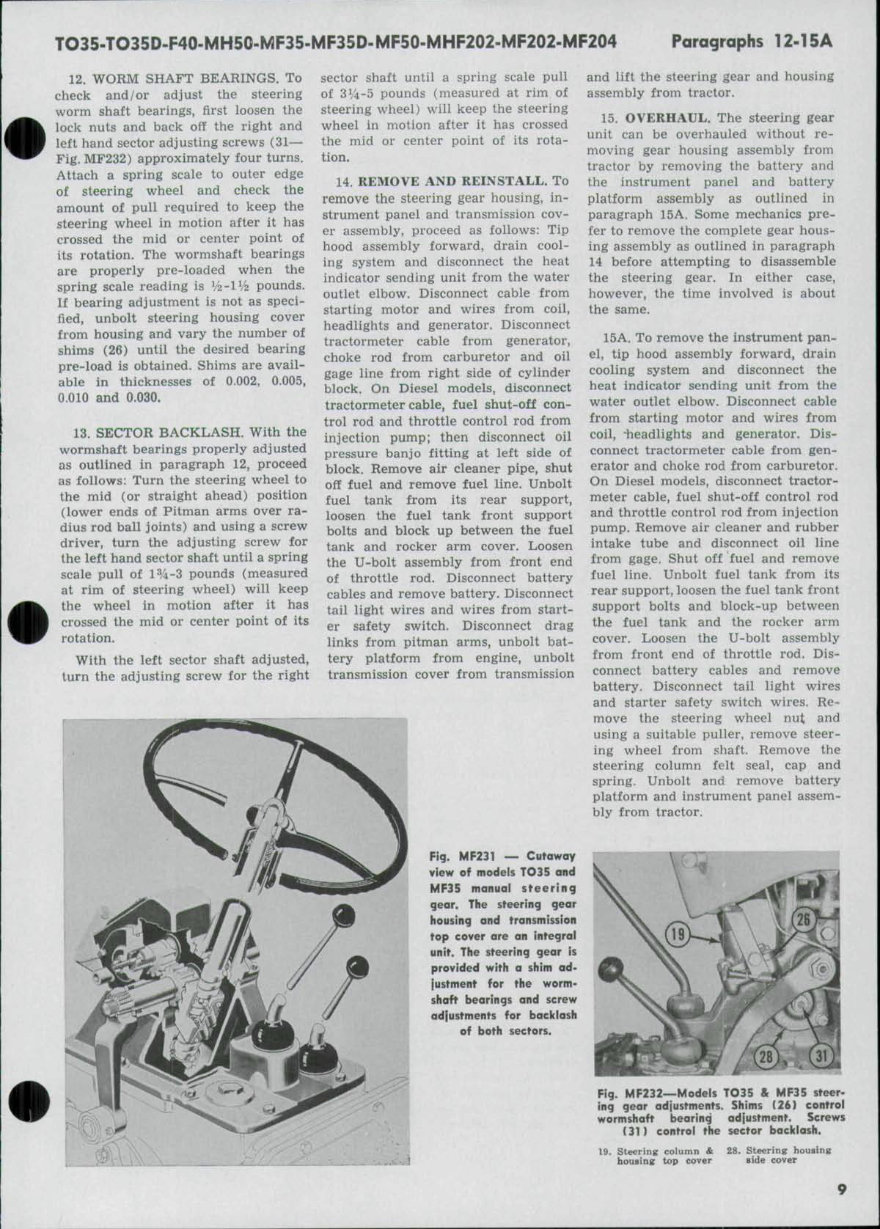
Content Overview:
Front Axle and Steering Assembly
Continental, Standard, and Perkins Engine Service
Cooling Systems, Fuel Pumps, and Carburetor Repair
Ignition, Starter, Generator, and Electrical Circuits
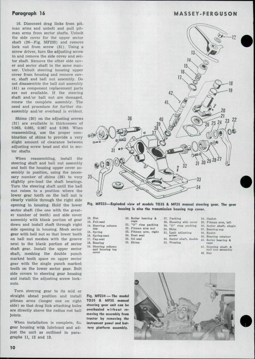
Transmission and Clutch Assembly (Single and Dual)
Rear Axle Disassembly and Inspection
Brake Servicing Procedures
Hydraulic System Troubleshooting and Repairs
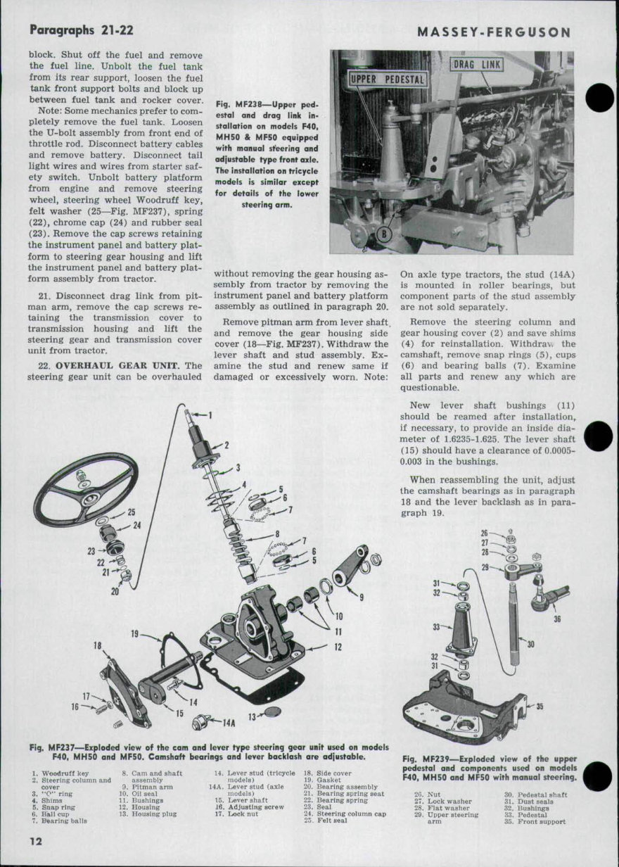
Power Take-Off (PTO) and Belt Pulley Information
Lubrication Points, Factory Clearances, and Specs
Whether you’re restoring a TO35 in your garage or maintaining a workhorse MF202 in the field, this manual is the original reference you need to get the job done right.
Printable: Yes Language: English Compatibility: Works on all devices (Windows, macOS, iOS, Android) Requirements: Any PDF reader (e.g. Adobe Reader)
Recently Viewed
5,521,897Happy Clients
2,594,462eManuals
1,120,453Trusted Sellers
15Years in Business
Price:
Actual Price:
Massey Ferguson TO35/MF35/F40/MH50/MF50/MHF202/MF202/MF204 Tractors OEM Service & Repair Manual