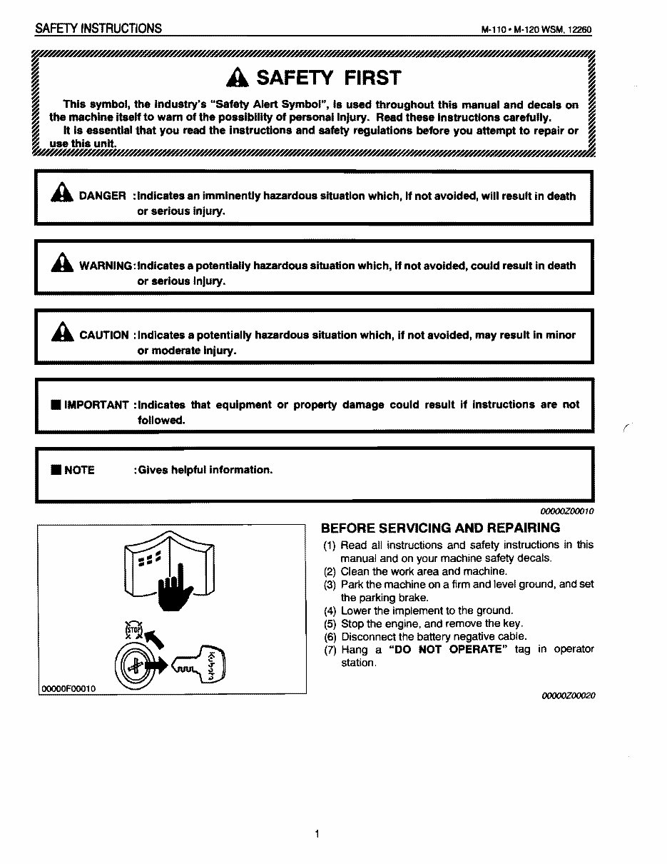
I SAFETY INSTRUCTIONS M-l10· M-120 WSM. 12260 ~~~~~ ~UUMI'H/UHH.w,wUUMl'~~AW~ ~ ~ A SAFETY FIRST :g ~ ~ This symbol, the industry's "Safety Alert Symbol", is used throughout this manual and decals on ~ ~ ~ the machine itselfto warn ofthe possibility of personal InJury. Read these instructions carefully. ~ ~ It is essential that you read the instructions and safety regulations before you aHempt to repair or ~ I~~~ ~ A DANGER : Indicates an imminently hazardous situation which, if not avoided, will result in death or serious injury. A WARNING: Indicates a potentially hazardous situation which, If not avoided, could result in death or serious injury. A CAUTION : Indicates a potentially hazardous situation which, if not avoided, may result in minor or moderate inJury . • IMPORTANT :Indlcates that equipment or property damage could result if instructions are not followed. : Gives helpful Information. I OOOOOFOOO10 OOOOOZOOO10 BEFORE SERVICING AND REPAIRING (1) Read all instructions and safety instructions in this manual and on your machine safety decals. (2) Clean the work area and machine. (3) Park the machine on a firm and level ground, and set the parking brake. (4) Lower the implement to the ground. (5) Stop the engine, and remove the key. (6) Disconnect the battery negative cable. (7) Hang a "DO NOT OPERATE" tag in operator station. OOOOOZOOO20 1
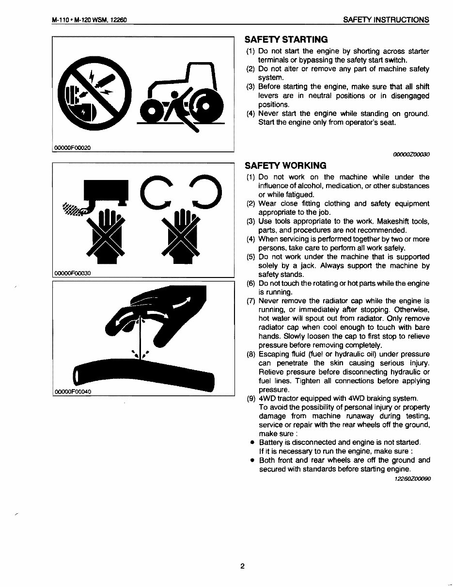
M·llO- M-l20WSM, 12260 SAFETY INSTRUCTIONS OOOOOFOOO20 OOOOOFOOO3O SAFETY STARTING (1) Do not start the engine by shorting across starter terminals or bypassing the safety start switch. (2) Do not alter or remove any part of machine safety system. (3) Before starting the engine, make sure that all shift levers are in neutral positions or in disengaged positions. (4) Never start the engine while standing on ground. Start the engine only from operator's seat. OOOOOZOOO3O SAFETY WORKING (1) Do not work on the machine while under the influence of alcohol, medication, or other substances or while fatigued. (2) Wear close fitting clothing and safety equipment appropriate to the job. (3) Use tools appropriate to the work. Makeshift tools, parts, and procedures are not recommended. (4) When servicing is performed together by two or more persons, take care to perform all work safely. (5) Do not work under the machine that is supported solely by a jack. Always support the machine by safety stands. (6) Do not touch the rotating or hot parts while the engine is running. (7) Never remove the radiator cap while the engine is running, or immediately after stopping. Otherwise, hot water will spout out from radiator. Only remove radiator cap when cool enough to touch with bare hands. Slowly loosen the cap to first stop to relieve pressure before removing completely. (8) Escaping fluid (fuel or hydraulic oil) under pressure can penetrate the skin causing serious injury. Relieve pressure before disconnecting hydraulic or fuel lines. Tighten all connections before applying pressure. (9) 4WD tractor equipped with 4WD braking system. To avoid the possibility of personal injury or property damage from machine runaway during testing, service or repair with the rear wheels off the ground, make sure : • Battery is disconnected and engine is not started. If it is necessary to run the engine, make sure: • Both front and rear wheels are off the ground and secured with standards before starting engine. 12260Z00090 2
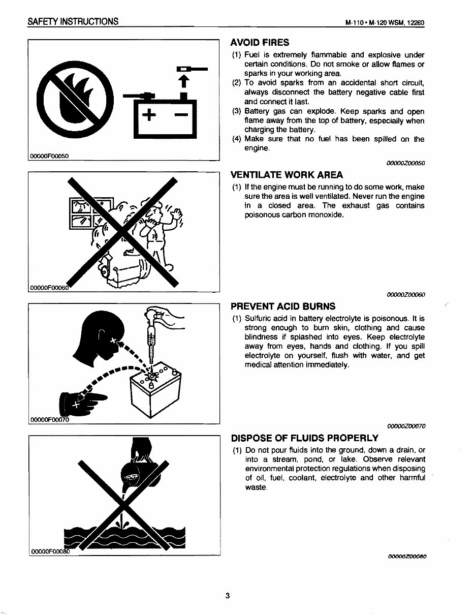
SAFETY INSTRUCTIONS M-ll0· M-l20WSM, 12260 • + - OOOOOFOOO50 AVOID FIRES (1) Fuel is extremely flammable and explosive under certain conditions. Do not smoke or allow flames or sparks in your working area. (2) To avoid sparks from an accidental short circuit, always disconnect the battery negative cable first and connect it last. (3) Battery gas can explode. Keep sparks and open flame away from the top of battery, especially when charging the battery. (4) Make sure that no fuel has been spilled on the engine. OOOOOZOOOSO VENTILATE WORK AREA (1) If the engine must be running to do some work, make sure the area is well ventilated. Never run the engine in a closed area. The exhaust gas contains poisonous carbon monoxide. OOOOOZOOO6O PREVENT ACID BURNS (1) Sulfuric acid in battery electrolyte is poisonous. It is strong enough to burn skin. clothing and cause blindness if splashed into eyes. Keep electrolyte away from eyes. hands and clothing. If you spill electrolyte on yourself, flush with water. and get medical attention immediately. OOOOOZOOO70 DISPOSE OF FLUIDS PROPERLY (1) Do not pour fluids into the ground. down a drain, or into a stream. pond. or lake. Observe relevant environmental protection regulations when disposing of Oil. fuel, coolant, electrolyte and other harmful waste. OOOOOZ00080 3
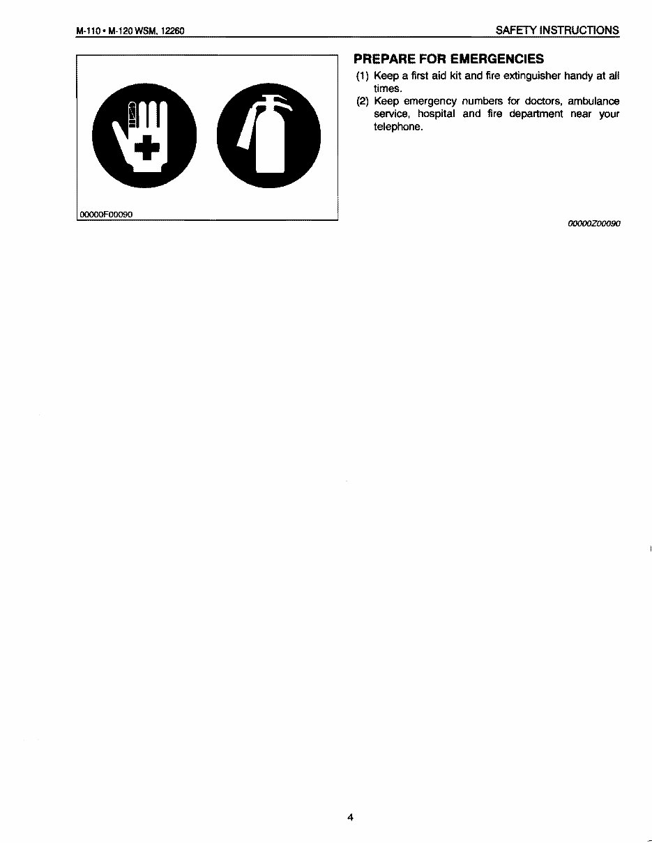
M-110- M·120WSM. 12260 SAFETY INSTRUCTIONS OOOOOF00090 PREPARE FOR EMERGENCIES (1) Keep a first aid kit and fire extinguisher handy at all times. (2) Keep emergency numbers for doctors, ambulance service, hospital and fire department near your telephone. OOOOOZOOO9O 4
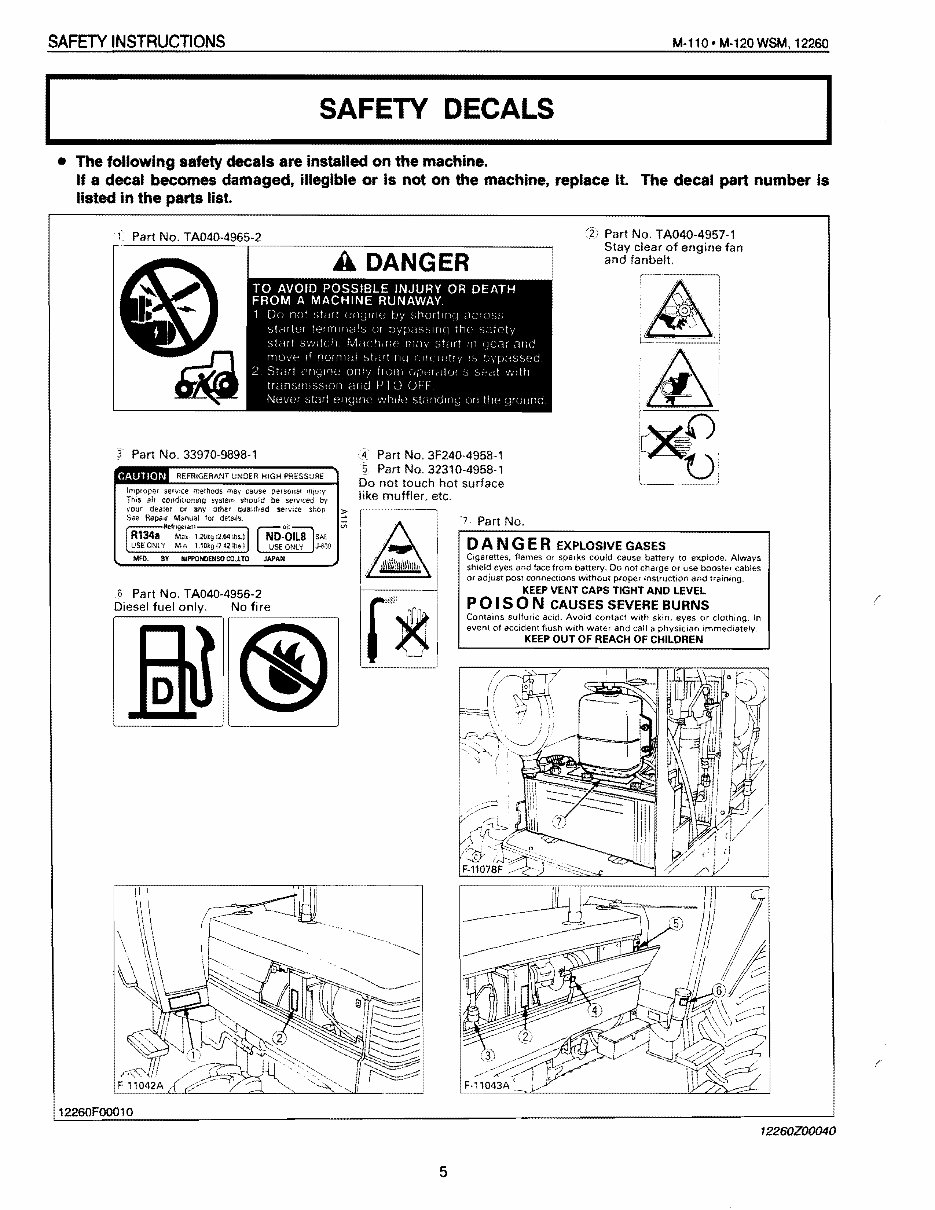
SAFETY INSTRUCTIONS M·ll0· M·120 WSM, 12260 SAFETY DECALS I I • The following safety decals are installed on the machine. If a decal becomes damaged, illegible or is not on the machine, replace It. The decal part number Is listed in the parts list. Part No. TA040-4957-1 Stay clear of engine fan and fanbelt. f Part No. TA040-4965-2 ~. Part No. 3F240-4958-1 § Part No. 32310-4958-1 Do not touch hot surface sen/Ice methods may cause persona! '"I;;ry condltJomog syslem should be serviced by dealer or any other Qua'ifted service shOD Repair Manual tor de:ads Refngera01-----, R134a M" l.2V'g :2.64 ,b,.) USE ONI Y M.n 1-10'9 1142 lb. I MFD. BY "'-::":7::"c.::.;....JJ.6J9 like muffler, etc. I'~ II A! /~ 6 Part No. TA040·4956·2 Ir .... D"",,",I No fi" II @g @~- 7 Part No. DAN G E R EXPLOSIVE GASES Cigarettes, flames or sparks could cause battery to Always shield eyes and face from battery. 00 not charge or use cables Of adjust POSt connectIons without proper instruction and training. KEEP VENT CAPS TIGHT AND LEVEL POI SON CAUSES SEVERE BURNS Contains sulfuric acid. Avoid contact With skin, eyes or clothing. In event of accident flush with water and call a physician ImmedIately KEEP OUT OF REACH OF CHILDREN 12260FOO010 12260Z00040 5
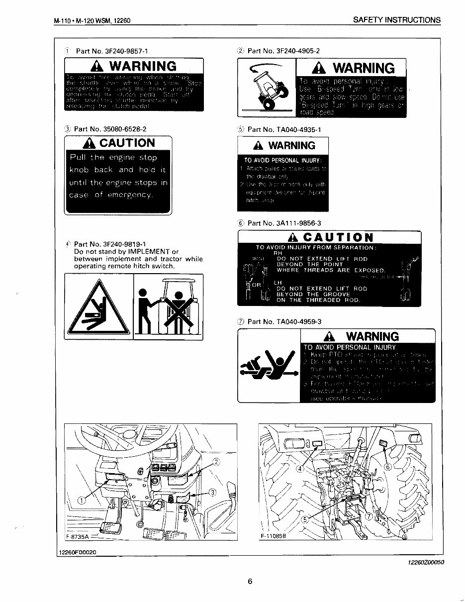
M-110·M-120WSM,12260 SAFETY INSTRUCTIONS 1 Part No. 3F240-9857-1 Part No. 35080-6528-2 f\ Part No. 3F240-9819-1 Do not stand by IMPLEMENT or between implement and tractor while operating remote hitch switch. (2) Part No. 3F240-4905-2 :i! Part No. TA040-4935-1 ~f5) Part No. 3A 111-9856-3 CD Part No. TA040-4959-3 12260F00020 12260Z00050 6
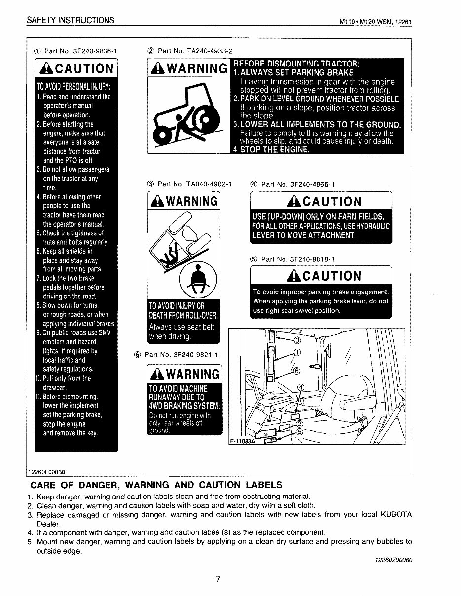
SAFETY INSTRUCTIONS M110*M120WSM,12261 @ Part No. 3F240-9818-1 CARE OF DANGER, WARNING AND CAUTION LABELS 1. Keep danger, warning and caution labels clean and free from obstructing material. 2. Clean danger, warning and caution labels with soap and water, dry with a soft cloth. 3. Replace damaged or missing danger, warning and caution labels with new labels from your local KUBOTA Dealer. 4. If a component with danger, warning and caution labes (s) as the replaced component. 5. Mount new danger, warning and caution labels by applying on a clean dry surtace and pressing any bubbles to outside edge. 12260Z00060 ill Part No. 3F240-9836-1 ACAUTION TO AVOID PERSONAL INJURY: 1. Read and understand the operator's manual before operation. 2. Before starting the engine, make sure that everyone is at a sate distance from tractor and the PTa is off. 3. Do not allow passengers on the tractor at any time. 4. Before allowing other people to use the tractor have them read the operator's manual. 5. Check the tightness of nuts and bolts regularly, 6. Keep all shields in place and stay away from all moving parts. 7. Lock the two brake pedals together before driving on the road. 8. Slow down for turns. or rough roads. or when applying individual brakes. 9. On public roads use SMV emblem and hazard lights. if required by local traffic and safety regulations. 10. Pull only from the drawbar. 11. Before dismounting. lower the implement, set the parking brake, stop the engine and remove the key, 12260F00030 CV Part No. TA240-4933-2 @ Part No. TA040-4902-1 @ Part No. 3F240-4966-1 TO AVOID INJURY OR DEATH FROM ROLL·OVER: Always use seat belt when driVing. @ Part No. 3F240-9821-1 ACAUTION 7
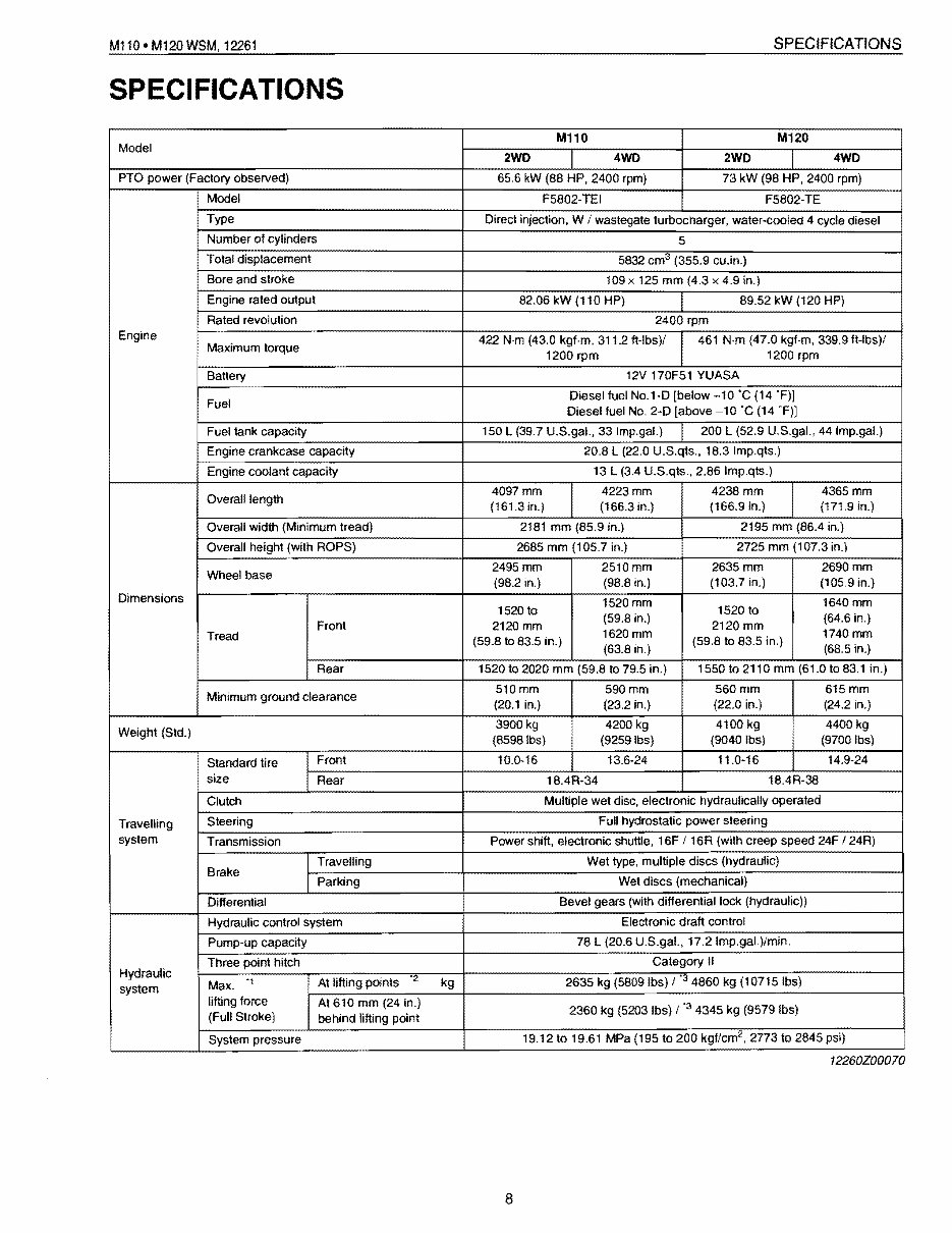
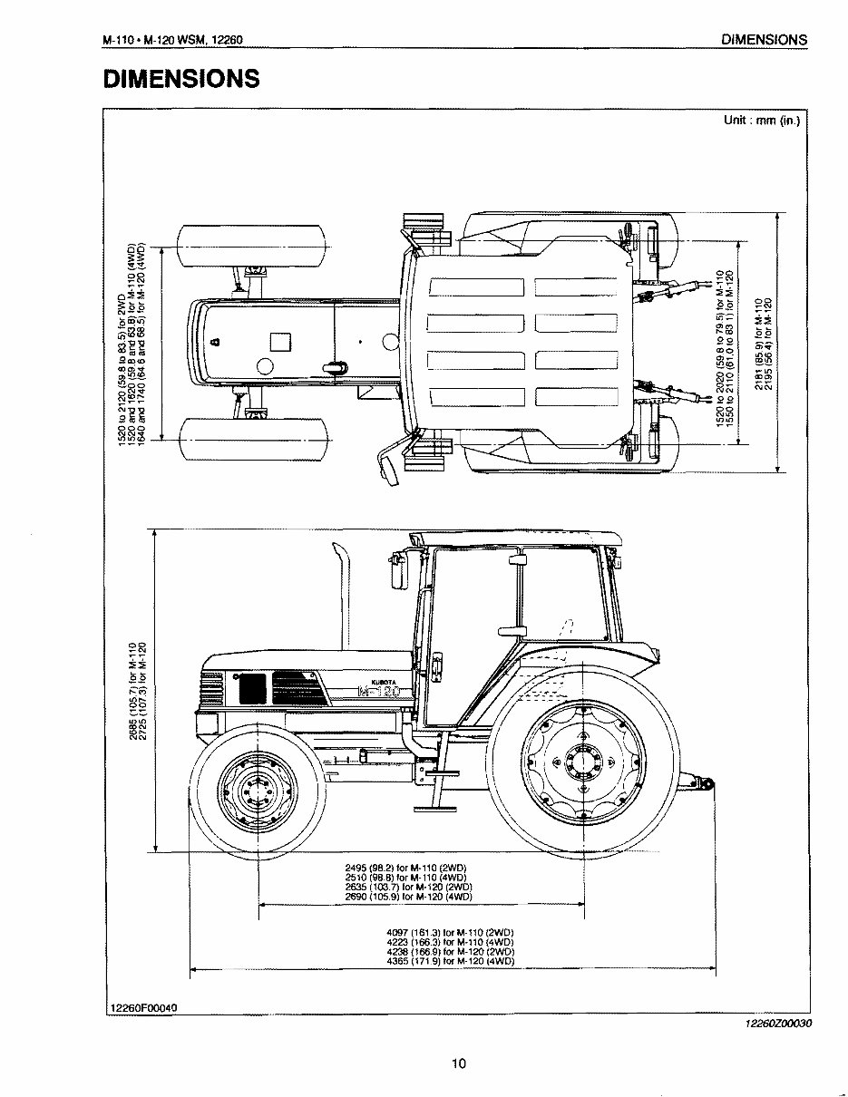
M110. M120 WSM. 12261 SPECIFICATIONS SPECI FICATIONS MHO M120 Model 2WD 4WD 2WD 4WD PTO power (Factory observed) 65.6 kW (88 HP. 2400 rpm) 73 kW (98 HP. 2400 rpm) Model F5802-TEI F5802-TE Type Direct injection. W / wastegate turbocharger. water-cooled 4 cycle diesel Number of cylinders 5 Total displacement 5832 cm 3 (355.9 cu.in.) Bore and stroke 109 x 125 mm (4.3 x 4.9 in.) Engine rated output 82.06 kW (110 HP) 89.52 kW (120 HP) Rated revolution 2400 rpm Engine 422 N·m (43.0 kgf·m, 311.2 ft-lbs)/ 461 N·m (47.0 kgf·m, 339.9 ft-Ibs)/ Maximum torque 1200 rpm 1200 rpm Banery 12V 170F51 YUASA Fuel Diesel fuel No.1-D [below -10'C (14 'F)) Diesel fuel No. 2-D [above -10 'C (14 'F)) Fuel tank capacity 150 L (39.7 U.S.gaL, 33 Imp.gaL) 200 L (52.9 U.S.gal.. 44 Imp.gaL) Engine crankcase capacity 20.8 L (22.0 U.S.qts .• 18.3 Imp.qts.) Engine coolant capacity 13 L (3,4 U.S.qts., 2.86 Imp.qts.) Overall length 4097mm 4223mm 4238 mm 4365mm (161.3 in.) (166.3 in.) (166.9 in.) (171.9 in.) Overall width (Minimum tread) 2181 mm (85.9 in.) 2195 mm (86.4 in.) Overall height (with ROPS) 2685 mm (105.7 in.) 2725 mm (107.3 in.) Wheel base 2495 mm 2510 mm 2635 mm 2690mm (98.2 in.) (98.8 in.) (103.7 in.) (105.9 in.) Dimensions 1520 mm 1640 mm 1520 to (59.8 in.) 1520 to (64.6 in.) Front 2120 mm 2120 mm Tread (59.8 to 83.5 in.) 1620mm (59.8 to 83.5 in.) 1740mm (63.8 in.) (68.5 in.) Rear 1520 to 2020 mm (59.8 to 79.5 in.) 1550 to 2110 mm (61.0 to 83.1 in.) Minimum ground clearance 510mm 590mm 560mm 615mm (20.1 in.) (23.2 in.) (22.0 in.) (24.2 in.) Std.) 3900 kg t- 4200k, 4100 kg 4400 kg (8598Ibs) (9259Ibs) (9040Ibs) (9700Ibs) Standard tire Front 10.0-16 13.6·24 11.0-16 14.9-24 size Rear 18.4R-34 18.4R-38 Clutch Multiple wet disc, electronic hydraulically operated Travelling Steering Full hydrostatic power steering system Transmission Power shift, electronic shuttle. 16F / 16R (with creep speed 24F / 24R) Brake Travelling Wet type, multiple discs (hydraulic) Parking Wet discs (mechanical) Differential Bevel gears (with differential lock (hydraulic)) Hydraulic control system Electronic draft control Pump-up capacity 78 L (20.6 U.S.gal., 17.2 Imp.gal.)/min. Hydraulic Three point hitch Category II '1 At lifting points '2 kg 2635 kg (5809Ibs) /'34860 kg (10715Ibs) system Max. lifting force At 610 mm (24 in.) 2360 kg (5203 Ibs) / '3 4345 kg (9579 Ibs) (Full Stroke) behind lifting point System pressure 19.12 to 19.61 MPa (195 to 200 kgf/cm 2 , 2773 to 2845 psi) 12260Z00070 8
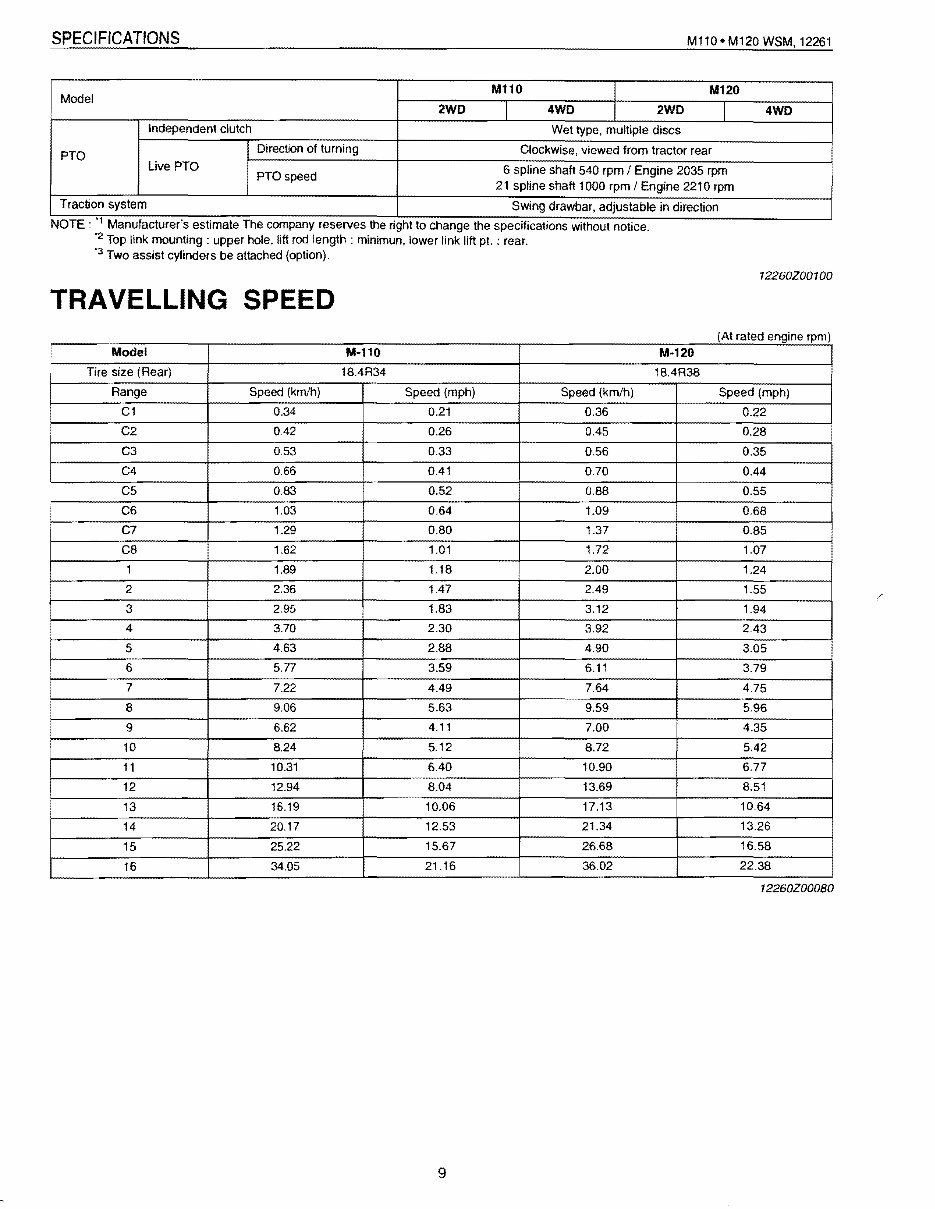
SPECIFICATIONS M110· M120 W8M, 12261 M110 I M120 Model 2WD I 4WD I 2WD I Independent clutch Wet type, multiple discs PTO Direction of turning Clockwise, viewed from tractor rear Live PTO 6 spline shaft 540 rpm I Engine 2035 rpm PTOspeed 21 spline shaft 1000 rpm I Engine 2210 rpm Traction system Swing drawbar, adjustable in direction . 'I . . NOTE. Manufacturer s estimate The company reserves the nght to change the speCifications without notice . "2 Top link mounting: upper hole, lift rod length: minimun, lower link lift pI. : rear. "3 Two assist cylinders be attached (option). 4WD I 12260Z00100 TRAVELLING SPEED (At rated engine rpm) Model M-110 M·120 Tire size (Rear) 18.4R34 18.4R38 Range Speed (km/h) Speed (mph) Speed (km/h) Speed (mph) C1 0.34 0.21 0.36 0.22 C2 0.42 0.26 0.45 0.28 C3 0.53 0.33 0.56 0.35 C4 0.66 0.41 0.70 0.44 C5 0.83 0.52 0.88 0.55 C6 1.03 0.64 1.09 0.68 C7 1.29 0.80 1.37 0.85 C8 1.62 1.01 1.72 1.07 1 1.89 1.18 2.00 1.24 2 2.36 1.47 2.49 1.55 3 2.95 1.83 3.12 1.94 4 3.70 2.30 3.92 2.43 i 5 4.63 2.88 4.90 3.05 6 5.77 3.59 6.11 3.79 7 7.22 4.49 7.64 4.75 • 8 9.06 5.63 9.59 5.96 9 6.62 4.11 7.00 4.35 I 10 8.24 5.12 8.72 5.42 11 10.31 6.40 10.90 6.77 12 12.94 8.04 13.69 8.51 13 16.19 10.06 17.13 10.64 14 20.17 12.53 21.34 13.26 15 25.22 15.67 26.68 16.58 16 34.05 21.16 36.02 22.38 12260Z00080 9
This is the Kubota M120 Tractor Service & Repair Manual, a comprehensive guide for servicing and repairing the Kubota M120 Tractor. It contains step-by-step instructions, diagrams, illustrations, wiring schematics, and specifications necessary for troubleshooting and repairing the tractor.
Divided into three parts - General, Mechanism, and Servicing - this manual provides information on tractor identification, general precautions, maintenance checklists, special tools, construction, function, troubleshooting, servicing specifications, tightening torque, disassembling, assembling, and more.
Designed for both professional mechanics and DIY enthusiasts, this manual offers the same specifications and procedures available to an authorized dealer service department. It is written by the manufacturers and includes clear and concise text combined with illustrations, making it suitable for individuals with basic mechanical knowledge.
The Kubota M120 Tractor Service & Repair Manual is available in .PDF format, viewable on PC, Mac, and various devices, including phones and e-readers. It is compatible with all versions of Windows and Mac, and can be printed for easy reference.
Topics covered in this manual include lubrication and maintenance, suspension, differential, brakes, cooling, electronic control modules, engine systems, steering, tires/wheels, heating & air conditioning, emissions control, and more. It also includes information on troubleshooting, routine maintenance, attachments, electrics, hydraulics, gearboxes, and running gear.
All pages are printable, allowing for easy access in the garage or workshop, ultimately saving money by enabling self-repairs. With easy-to-follow, step-by-step instructions, this manual is a valuable resource for maintaining and repairing the Kubota M120 Tractor.