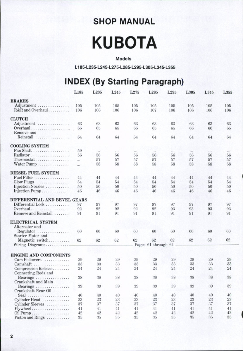
DUAL DIMENSIONS This service manual provides specifications in both the U.S. Customary and Metric (SI) systems of measurement. The first specification is given in the measuring system per- ceived by us to be the preferred system when servicing a particuiar component, whiie the second specification (given in parenthesis) is the converted measurement. For instance, a specification of "0.28 mm (0.011 inch)" wouid indicate that we feei the preferred measure- ment, in this instance, is the metric system of measurement and the U.S. system equivaient of 0.28 mm is 0.011 inch. CONDENSED SERVICE DATA L185 L235 GENERAL Engine Make Engine Model Z751A D1102A Number of Cylinders 2 3 Bore 76 mm 76 mm (3 in.) (3 in.) Stroke Displacement 743 cc 1115 cc (45.3 cu.in.) (68.3 cu.in.) Cylinder Sleeves Battery-Volts Ground Polarity Forward Speeds TUNE-UP Compression Pressure — FiringOrder 1-2 1-2-3 Valve Clearance- Intake and Exhaust Injection Timing (BTDC) - . . Timing Mark Location Injection Pressure Low Idle Speed (rpm) High Idle Speed (rpm) 2950 2750 Rated Speed (rpm) 2800 2600 Rated Power at Pto Shaft 11.5 kW 14.61 kW (15.45 HP) (19.59 HP) SIZES-CLEARANCES Crankshaft Main Journal- Diameter Bearing Clearance - Front Bearing All Other Bearings Crankshaft Crankpin Journal - Diameter Bearing Clearance Crankshaft End Play Camshaft Journal - Diameter Bearing Clearance L24S Own — DllOlA 3 76 mm (3 in.) — 82 mm — (3.23 in,) 1115 cc (68.3 cu.in.) Dry — 12 — Negative 8 L275 L285 - 3,235 kPa (470 psi) 1-2-3 — 0.18-0.22 mm (0.007-0.009 in.) -25° - Flywheel -13720-14700 kPa (1990-2135 psi) 800-850 2950 2800 16.4 kW (22 HP) -51.921-51.940 mm (2.0441-2.0449 in.) -0.040-0.118 mm - (0.0016-0.0046 in.) — 0.040-0.104 mm- (0.0016-0.0041 in.) -43.959-43.975 mm (1.7307-1.7313 in.) -0.035-0.093 mm - (0.0014-0.0037 in.) — 0.15-0.31 mm - (0.006-0.012 in.) -39.934-39.950 mm (1.5722-L5728 in.) — 0.050-0.091 mm - (0.0020-0.0036 in.) D1302A 3 82 mm (3.23 in.) V1501A 4 76 mm (3 in.) 1299 cc (79.3 cu.in.) 1487 cc (90.7 cu.in.) 1-2-3 1-3-4-2 2750 2600 17.5 kW (23.42 HP) 2550 2400 19.8 kW (26.45 HP)
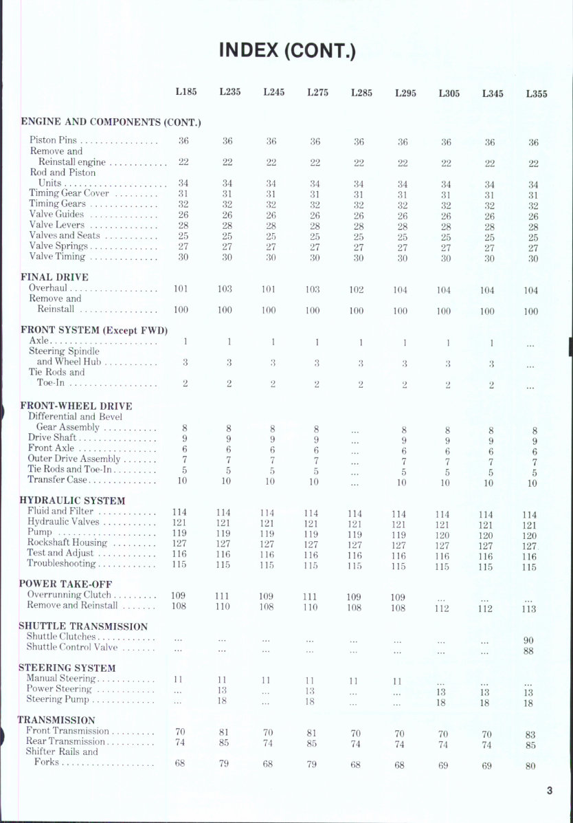
CONDENSED SERVICE DATA (CONT.) SIZES-CLEARANCES (CONT.) ^^^^ ^^^^ ^^^^ ^275 Cam Height- Intake and Exhaust . 33.36 mm (1.3134 in.) Piston Pin- I^ia'^eter 23.002-23.011 mm (0.9056-0.9059 in.) Clearance in Rod -0.014-0.038 mm (0.0006-0.0015 in.) Valve Seat Angle- Intake and Exhaust . 450 CAPACITIES CrankcaseOil 3.8 L 6.1 L 6.1 L 6.1 L r. ,• c. (4.0 qts.) (6.4 qts.) (6.4 qts.) (6.4 qts.) CoolmgSystem 5.3 L 6.6 L 6.6 L 6.6 L . . (5.6 qts.) (7.0 qts.) (7.0 qts.) (7.0 qts.) Iransmission- 2WD 22 L 24 L 22 L 24 L ,,,,^ (23 qts.) (25 qts.) (23 qts.) (25 qts.) 4WD 23 L 24 L 23 L 24 L ^, .^ ^ (24 qts.) (25 qts.) (24 qts.) (25 qts.) PluidType — Kubota UDT Transmission Fluid - Front Axle Differential Case(4WD) 1.1 L 2.3 L 1,1 L 2.6 L ™ ..^ (1.2 qts.) (2.4 qts.) (1.2 qts.) (2.7 qts.) FluidType SAE 80 or 90 Gear Oil Front Axle Outer Drive Case (4WD)-Each 0.8 L 0.3 L 0.8 L 0.3 L (0-8 qts.) (0.3 qts.) (0.8 qts.) (0.3 qts.) FluidType SAE 80 or 90 Gear Oil Steering Gear Box (Manual) ^0.3L T.T . (^-3 qts.) FluidType SAE 80 or 90 Gear Oil CONDENSED SERVICE DATA L295 GENERAL Engine Make ^__^ Engine Model D1301A Number of Cylinders 3 Bore ' 82 mm (3.23 in.) Stroke Displacement 1299 cc (79.8 cu.in.) Cylinder Sleeves Battery-Volts Ground Polarity Forward Speeds TUNE-UP Compression Pressure Firing Order 1-2-3 Valve Clearance- Intake and Exhaust Injection Timing (BTDC) Timing Mark Location Injection Pressure L305 L345 -Own D1301A 3 82 mm (8.28 in.) -82 mm V1501A 4 76 mm (8 in.) (8.28 in.) 1299 CC 1487 CC (79.8 cu.in.) (90.7 cu.in.) Dry . 12 L285 8.9 L (9.4 qts.) 7.0 L (7.4 qts.) 27 L (29 qts.) L355 V1702A 4 82 mm (8.28 in.) 1782 CC (105.6 cu.in.) - Negative 8 — 1-2-8 -8285kPa (470 psi) 1-8-4-2 1-8-4-2 -0.18-0.22mm (0.007-0.009 in.) 25° - Flywheel -18720-14700 kPa- (1990-2185 psi)
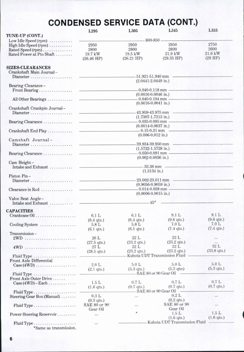
CONDENSED SERVICE DATA (CONT.) L295 TUNE-UP (CONT.) Low Idle Speed (rpm) High Idle Speed (rpm) . . . Rated Speed (rpm) Rated Power at Pto Shaft 2950 2800 19.7 kW (26.46 HP) SIZES-CLEARANCES Crankshaft Main Journal - Diameter Bearing Clearance- Front Bearing All Other Bearings Crankshaft Crankpin Journal- Diameter Bearing Clearance Crankshaft End Play Camshaft Journal- Diameter Bearing Clearance Cam Height- Intake and Exhaust Piston Pin- Diameter Clearance in Rod Valve Seat Angle- Intake and Exhaust CAPACITIES Crankcase Oil 6.1 L (6.4 qts.) Cooling System 5.8 L (6.1 qts.) Transmission - 2WD 26 L (27.5 qts.) 4WD 27 L (28.5 qts.) Fluid Type Front Axle Differential Case(4WD) 2.0 L (2.1 qts.) Fluid Type Front Axle Outer Drive Case(4WD)-Each 1.5 L (1.6 qts.) Fluid Type Steering Gear Box (Manual) 0.3 L (0.3 qts.) Fluid Type SAE 80 or 90' Gear Oil Power Steering Reservoir Fluid Type *Same as transmission. L305 L345 -800-850- 2950 2800 19.5 kW (26.21 HP) 2950 2800 21.9 kW (29.35 HP) -51.921-51.940 mm (2.0441-2.0449 in.) -0.040-0.118 mm - (0.0016-0.0046 in.) — 0.040-0.104 mm - (0.0016-0.0041 in.) — 43.959-43.975 mm (1.7307-1.7313 in.) — 0.035-0.095 mm - (0.0014-0.0037 in.) — 0.15-0.31 mm - (0.006-0.012 in.) -39.934-39.950 mm (1.5722-1.5728 in.) — 0.050-0.091 mm - (0.002-0.0036 in.) -33.36 mm (1.3134 in.) -23.002-23.011 mm (0.9056-0.9059 in.) — 0.014-0.038 mm - (0.0006-0.0015 in.) -45° 6.1 L : (6.4 qts.) (6.1 qts.) • : 22 L (23.2 qts.) 22 L (23.2 qts.) - Kubota UDT Transmission Fluid 5.0 L 5.0 L (5.3 qts.) (5.3 qts:) SAE 80 or 90 Gear Oil — 9.1 (9.6 7.C (7.4 22 (23.2 22 (23.2 L qts.) )L qts.) L qts.) L qts.) 0.7 L 0.7 L (0.7 qts.) (0.7 qts.) SAE 80 or 90 Gear Oil — 0.2 L L355 2750 2600 21.6 kW (29 HP) 9.1 L (9.6 qts.) 7.0 L (7.4 qts.) 32 L (33.8 qts.) 5.0 L (5.3 qts.) 0.7 L (0.7 qts.) (0.2 qts.) SAE 80 or 90 Gear Oil 1.5 L (1.6 qts.) Kubota UDT Transmission Fluid 1.5 L (1.6 qts.) 6
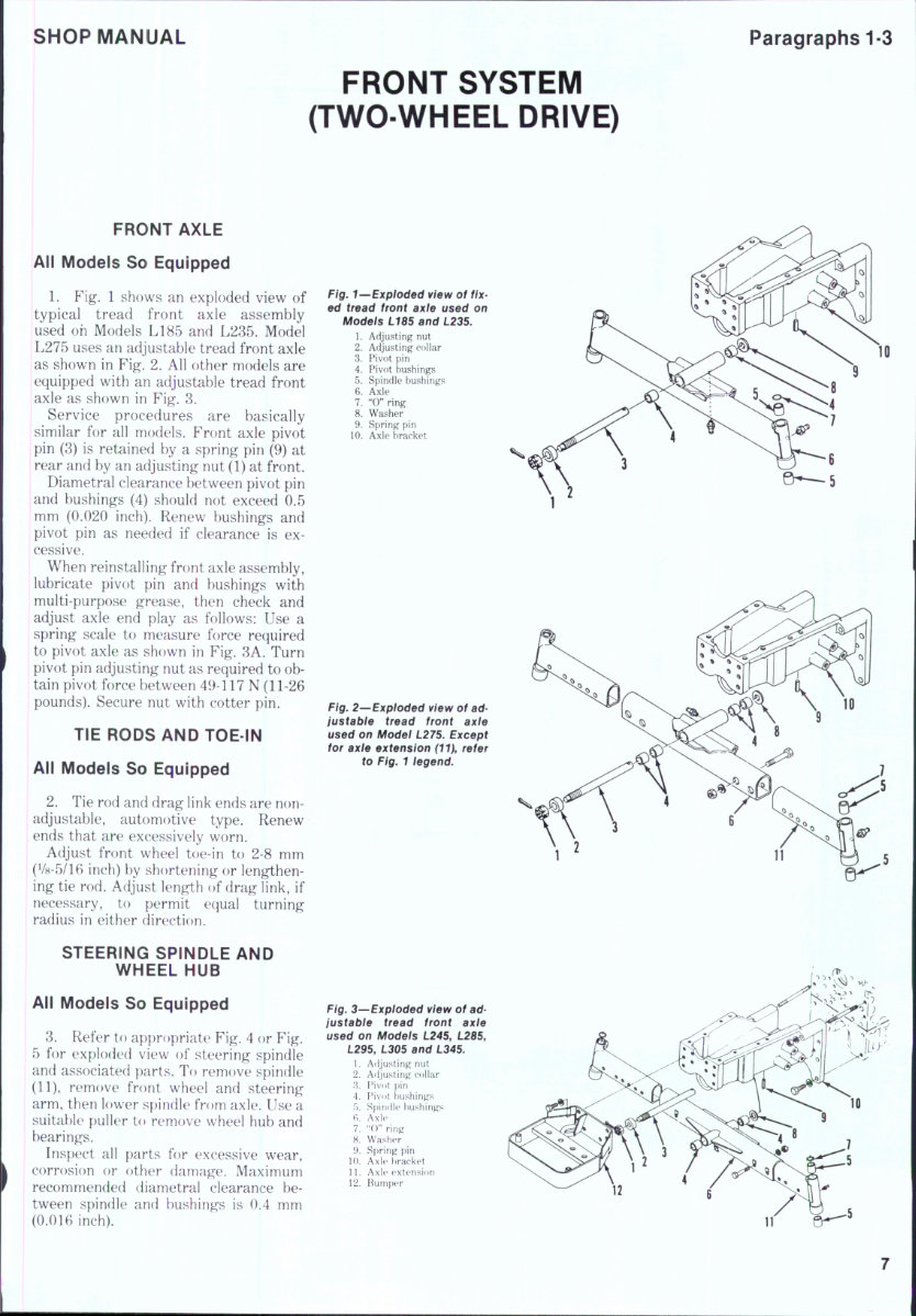
SHOP MANUAL Paragraphs 1-3 FRONT SYSTEM (TWO-WHEEL DRIVE) FRONT AXLE All Models So Equipped 1. Fig. 1 shows an exploded view of typical tread front axle assembly used oh Models L185 and L285. Model L275 uses an adjustable tread front axle as shown in Fig. 2. All other models are equipped with an adjustable tread front axle as shown in Fig. 8. Service procedures are basically similar for all models. Front axle pivot pin (8) is retained by a spring pin (9) at rear and by an adjusting nut (1) at front. Diametral clearance between pivot pin and bushings (4) should not exceed 0.5 mm (0.020 inch). Renew bushings and pivot pin as needed if clearance is ex- cessive. When reinstalling front axle assembly, lubricate pivot pin and bushings with multi-purpose grease, then check and adjust axle end play as follows: Use a spring scale to measure force required to pivot axle as shown in Fig. 8A. Turn pivot pin adjusting nut as required to ob- tain pivot force between 49-117 N (11-26 pounds). Secure nut with cotter pin. TIE RODS AND TOE-IN All Models So Equipped 2. Tie rod and drag link ends are non- adjustabie, automotive type. Renew ends that are excessively worn. Adjust front wheel toe-in to 2-8 mm (V8-5/16 inch) by shortening or lengthen- ing tie rod. Adjust length of drag link, if necessary, to permit equal turning radius in either direction. STEERING SPINDLE AND WHEEL HUB All Models So Equipped 8. Refer to appropriate Fig. 4 or Fig. 5 for exploded view of steering spindle and associated parts. To remove spindle (11), remove front wheel and steering arm, then lower spindle from axle. Use a suitable puller to remove wheel hub and bearings. Inspect al! parts for excessive wear, corrosion or other damage. Maximum recommended diametral clearance be- tween spindle and bushings is 0.4 mm (0.016 inch). Fig. 1—Expioded view of fix- ed tread front axle used on Motfe/s L185 and L235. 1. Adjusting nut 2. Adjusting collar 3. Pivot pin 4. Pivot bushings 5. Spindle bushings 6. Axle 7. "0" ring 8. Washer 9. Spring pin 10. Axle bracket en—5 Fig. 2—Expioded view of ad- justabie tread front axie used on Modei L275. Except for axle extension (11), refer to Fig. 1 legend. Fig. 3—Expioded view of ad- justabie tread front axle used on Modeis L245, L285, L295, L305 and L345. 1. Afljusting nut 2. Adjusting collar 3. Pivot i)in 4. Pivot bushings f). Spindle bushings fi. Axle 7. "()" ring 8. Washer 9. Spring pin 10. Axle bracket 11. Axk* extension 12. [^um[)er
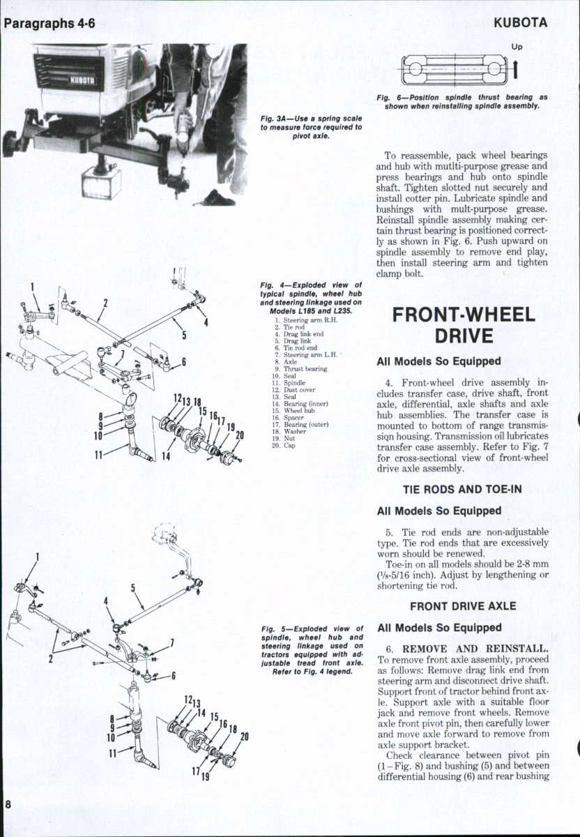
Paragraphs 4-6 KUBOTA ^ 11 Fig. BA—Use a spring scafe to measure force required to pivot axie. Fig. 4—'Expioded view of typicai spindie, wheei hub and steering iinkage used on Modeis L18S and L23S. 1. Steering arm R.H. 2. Tie rod 4. Drag link end 5. Drag link 6. Tie rod end 7. Steering arm L.H. * 8. Axle 9. Thrust bearing 10. Seal 11. Spindle , 12. Dust cover 13. Seal 14. Bearing (inner) 15. Wheel hub 16. Spacer 17. Bearing (outer) 18. Washer 19. Nut 20. Cap Fig. 5—Expioded view of splndie, wheei hub and steering ilni(age used on tractors equipped with ad- justabie tread front axie. Refer to Fig. 4 iegend. Fig. S—Position spindie thrust bearing as shown when reinstaiiing spindie assembiy. To reassemble, pack wheel bearings and hub with mutlti-purpose grease and press bearings and hub onto spindle shaft. Tighten slotted nut securely and install cotter pin. Lubricate spindle and bushings with mult-purpose grease. Reinstall spindle assembly making cer- tain thrust bearing is positioned correct- ly as shown in Fig. 6. Push upward on spindle assembly to remove end play, then install steering arm and tighten clamp bolt. > FRONT-WHEEL DRIVE All Models So Equipped 4. Front-wheel drive assembly in- cludes transfer case, drive shaft, front axle, differential, axle shafts and axle hub assemblies. The transfer case is mounted to bottom of range transmis- siQn housing. Transmission oil lubricates transfer case assembly. Refer to Fig. 7 for cross-sectional view of front-wheel drive axle assembly. TIE RODS AND TOE-IN All Models So Equipped 5. Tie rod ends are non-adjustable type. Tie rod ends that are excessively worn should be renewed. Toe-in on all models should be 2-8 mm (1/8-5/16 inch). Adjust by lengthening or shortening tie rod. FRONT DRIVE AXLE All Models So Equipped 6. REMOVE AND REINSTALL. To remove front axle assembly, proceed as follows: Remove drag link end from steering arm and disconnect drive shaft. Support front of tractor behind front ax- le. Support axle with a suitable floor jack and remove front wheels. Remove axle front pivot pin, then carefully lower and move axle forward to remove from axle support bracket. Check clearance between pivot pin (1-Fig. 8) and bushing (5) and between differential housing (6) and rear bushing
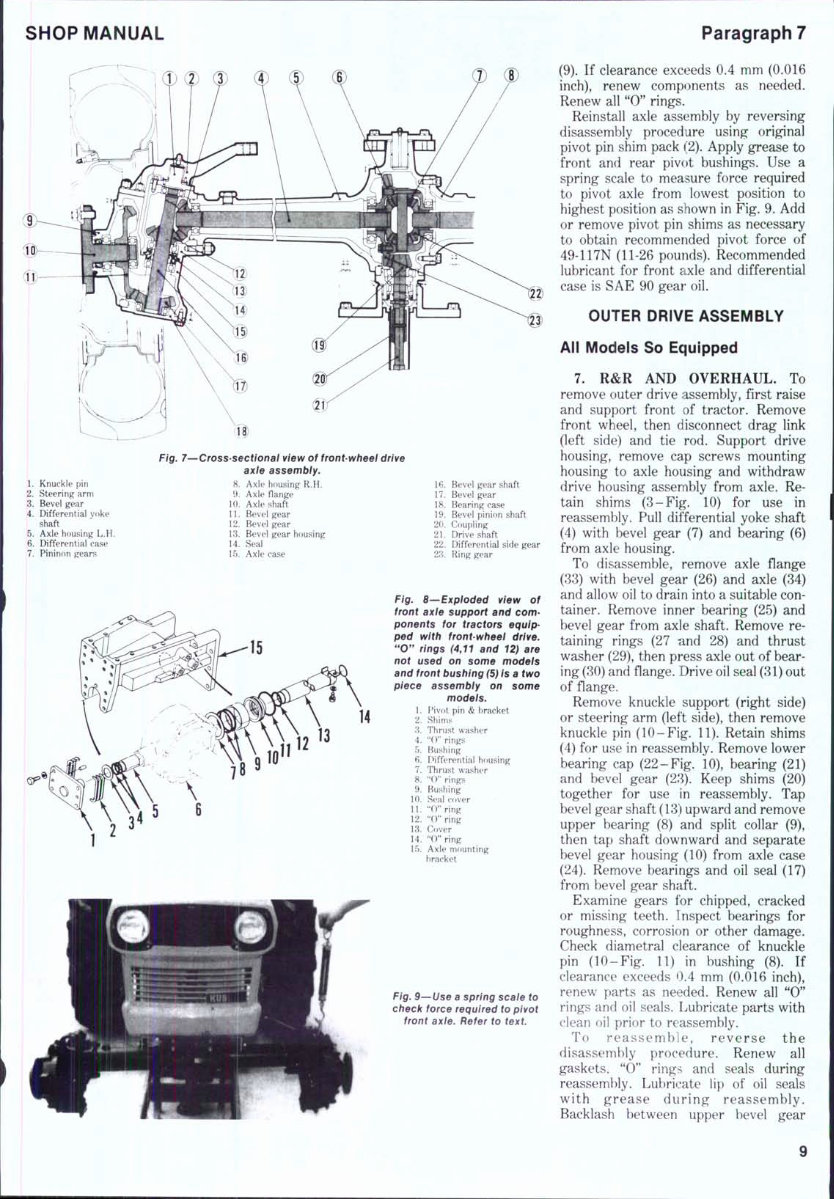
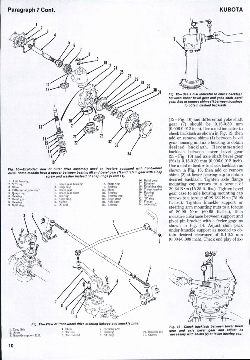
SHOP MANUAL Paragraph 7 Fig. 7—Cross-sectional view of front-wheel drive axie assembly. 1. Knuckle pin 8. Axle housing R.H. 2. Steering arm 9. Axle flange 3. Bevel gear 10. Axle shaft 4. Differential yoke 11. Bevel gear shaft ' 12. Bevel gear 5. Axle housing L.H. 13. Bevel gear housing 6. Differential ease 14. Seal 7. Pininon gears 15. Axle case 16. Bevel gear shaft 17. Bevel gear 18. Bearing case 19. Bevel pinion shaft 20. Coupling 21. Drive shaft 22. Differential side gear 23. Ring gear Fig. 8—Expioded view of front axte support and com- ponents for tractors equip- ped with front-wheel drive. "0" rings (4,11 and 12) are not used on some models and front bushing (5) is a two piece assembly on some models. 1. Pivot pin & bracket 2. Shims 3. Thrust washer 4. "()" rings 5. Bushing 6. Differential housing 7. Thrust washer 8. "(T' rings 9. Bushing 10. Seal cover 11. "0" ring 12. "O"ring 13. Cover 14. "0" ring 15. Axle mounting bracket Fig. 9—Use a spring scale to check force required to pivot front axle. Refer to text (9). If clearance exceeds 0.4 mm (0.016 inch), renew components as needed. Renew all "0" rings. Reinstall axle assembly by reversing disassembly procedure using original pivot pin shim pack (2). Apply grease to front and rear pivot bushings. Use a spring scale to measure force required to pivot axle from lowest position to highest position as shown in Fig. 9. Add or remove pivot pin shims as necessary to obtain recommended pivot force of 49-117N (11-26 pounds). Recommended lubricant for front axle and differential case is SAE 90 gear oil. OUTER DRIVE ASSEMBLY All Models So Equipped 7. R&R AND OVERHAUL, To remove outer drive assembly, first raise and support front of tractor. Remove front wheel, then disconnect drag link (left side) and tie rod. Support drive housing, remove cap screws mounting housing to axle housing and withdraw drive housing assembly from axle. Re- tain shims (3-Fig. 10) for use in reassembly. Pull differential yoke shaft (4) with bevel gear (7) and bearing (6) from axle housing. To disassemble, remove axle flange (33) with bevel gear (26) and axle (34) and allow oil to drain into a suitable con- tainer. Remove inner bearing (25) and bevel gear from axle shaft. Remove re- taining rings (27 nnd 28) and thrust washer (29), then press axle out of bear- ing (30) and flange. Drive oil seal (31) out of flange. Remove knuckle support (right side) or steering arm (left side), then remove knuckle pin (10-Fig. 11). Retain shims (4) for use in reassembly. Remove lower bearing cap (22-Fig. 10), bearing (21) and bevel gear (23). Keep shims (20) together for use In reassembly. T'ap bevel gear shaft (13) upward and remove upper bearing (8) and split collar (9), then tap shaft downward and separate bevel gear housing (10) from axle case (24). Remove bearings and oil seal (17) from bevel gear shaft. Examine gears for chipped, cracked or missing teeth. Inspect bearings for roughness, corrosion or other damage. Check diametral clearance of knuckle pin (10-Fig. 11) in bushing (8). If clearance exceeds 0.4 mm (0.016 inch), renew parts as needed. Renew all "0" rings and oil seals. Lubricate parts with clean oil prior to reassembly. To reassemble, reverse the disassembly procedure. Renew all gaskets. "0" rings and seals during reassembly. Lubricate lip of oil seals with grease during reassembly. Backlash between upper bevel gear
Paragraph 7 Cont. KUBOTA 34 Fig. lO—Bxploded view of outer drive assembiy used on tractors equipped with front-wheel drive. Some modeis have a spacer between bearing (6) and bevel gear (7) and retain gear with a cap screw and washer Instead of snap rings (5 and 11). 1. Axle housing 2. "0" ring 3. Shim 4. Differential yoke shaft 5. Snap ring 6. Bearing 7. Bevel gear 8. Bearing 9. Split ring 10. Bevel gear housing 11. Snap ring 12. Bevel gear 13. Bevel gear shaft 14. Bearing 15. Snap ring 16. Sleeve 17. Oil seal 18. Snap ring 19. Bearing 20. Shim 21. Bearing 22. Bearing cap 23. Bevel gear 24. Axle case 25. Bearing 26. 27. 28. 29. 30. 31. 32. 33. M. Bevel gear Retainer Retaining ring Thrust washer Bearing Oil seal "0" ring Flange Axle shaft 11 Pfg. tt~Wei¥ of front-wheel drive steering linkage and knuckle pins. 1. Drag link 2. Arms 3. Knuckle support R.H. Fig. 12—Use a dial indicator to check backiash between upper bevel gear and yoke shaft bevei gear. Add or remove shims (1) between housings to obtain desired backlash. (12-Fig. 10) and differential yoke shaft gear (7) should be 0.15-0.30 mm (0.006-0.012 inch). Use a dial indicator to check backlash as shown in Fig. 12, then add or remove shims (1) between bevel gear housing and axle housing to obtain desired backlash. Recommended backlash between lower bevel gear (23-Fig. 10) and axle shaft bevel gear (26) is 0.15-0.30 mm (0.006-0.012 inch). Use a dial indicator to check backlash as shown in Fig. 13, then add or remove shims (2) at lower bearing cap to obtain desired backlash. Tighten axle flange mounting cap screws to a torque of 20-34 N-m (15-25 ft.-lbs.). Tighten bevel gear case to axle housing mounting cap screws to a torque of 98-132 N-m (75-95 ft.-lbs.). Tighten knuckle support or steering arm mounting nuts to a torque of 80-90 N-m (60-65 ft.-lbs.), then measure clearance between support and pivot pin bracket with a feeler gage as shown in Fig. 14. Adjust shim pack under knuckle support as needed to ob- tain desired clearance of 0.1-0.2 mm (0.004-0.008 inch). Check end play of ax- 4. Shim 5. Tie rod 6. Tie rod end 7. Steering arm 8. Bushing 9. "0" ring 10. Knuckle pin 11. Gasket Fig. 13—Check backlash between iower bevel gear and axle bevei gear and adjust as necessary with shims (2) at lower bearing cap. 10
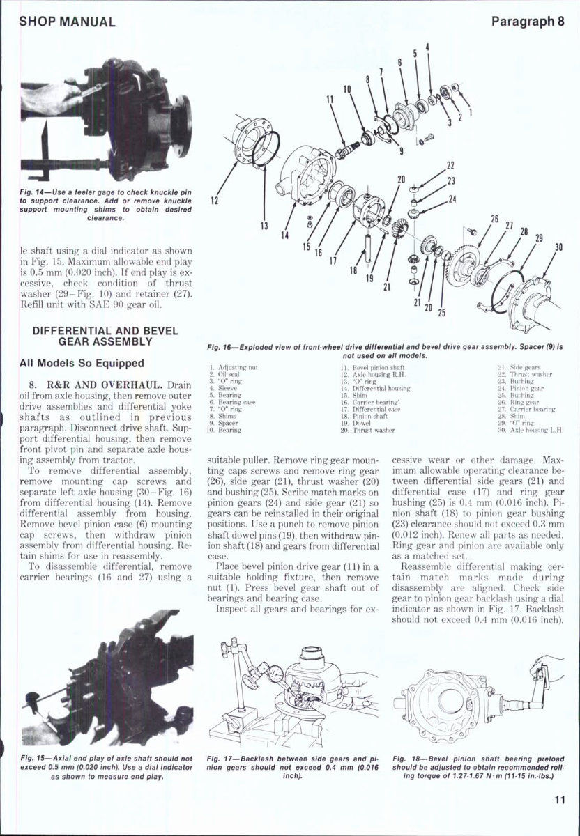
SHOP MANUAL Paragraph 8 Fig. 14—Use a feeier gage to check knuckle pin to support clearance. Add or remove knuckie support mounting shims to obtain desired ciearance. le shaft using a dial indicator as shown in Fig. 15. Maximum allowable end play is 0.5 mm (0.020 inch). If end play is ex- cessive, check condition of thrust washer (29-Fig. 10) and retainer (27). Refill unit with SAE 90 gear oil. DIFFERENTIAL AND BEVEL GEAR ASSEMBLY All Models So Equipped 8. R&R AND OVERHAUL. Drain oil from axle housing, then remove outer drive assemblies and differential yoke shafts as outlined in previous paragraph. Disconnect drive shaft. Sup- port differential housing, then remove front pivot pin and separate axle hous- ing assembly from tractor. To remove differential assembly, remove mounting cap screws and separate left axle housing (30-Fig. 16) from differential housing (14). Remove differential assembly from housing. Remove bevel pinion case (6) mounting cap screws, then withdraw pinion assembly from differential housing. Re- tain shims for use in reassembly. To disassemble differential, remove carrier bearings (16 and 27) using a 21 20 25 Fig. 16--Exploded view of front-wheel drive differentiai and bevei drive gear assembiy. Spacer (9) is not used on ail modeis. 1. Adjusting nut 2. Oil seal 3. "0" ring 4. Sleeve 5. Bearing 6. Bearing ease 7. "0" ring 8. Shims 9. Spacer 10. Bearing 11. Bevel pinion shaft 12. Axle housing R.H. 13. "0" ring 14. Differential housing 15. Shim 16. Carrier bearing' 17. Differential case 18. Pinion shaft 19. Dowel 20. Thrust washer 21. Side gears 22. Thrust washer 23. Bushing 24. Pinion gear 25. Bushing 2fi. Ring gear 27. Carrier tearing 28. Shim 29. "0" ring 'M). Axle housing L.H. suitable puller. Remove ring gear moun- ting caps screws and remove ring gear (26), side gear (21), thrust washer (20) and bushing (25). Scribe match marks on pinion gears (24) and side gear (21) so gears can be reinstalled in their original positions. Use a punch to remove pinion shaft dowel pins (19), then withdraw pin- ion shaft (18) and gears from differential case. Place bevel pinion drive gear (11) in a suitable holding fixture, then remove nut (1). Press bevel gear shaft out of bearings and bearing case. Inspect all gears and bearings for ex- cessive wear or other damage. Max- imum allowable operating clearance be- tween differential side gears (21) and differential case (17) and ring gear bushing (25) is 0.4 mm (0.016 inch). Pi- nion shaft (18) to pinion gear bushing (23) clearance should not exceed 0.3 mm (0.012 inch). Renew all parts as needed. Ring gear and pinion are available only as a matched set. Reassemble differential making cer- tain match marks made during disassembly are aligned. Check side gear to pinion gear backlash using a dial indicator as shown in Fig. 17. Backlash should not exceed 0.4 mm (0.016 inch). Fig. 15—Axial end piay of axie shaft shouid not exceed 0.5 mm (0.020 inch). Use a dial indicator as shown to measure end piay. Fig. 17^Backiash between side gears and pi- nion gears shouid not exceed 0.4 mm (0.016 inch). Fig. 18—'Bevei pinion shaft bearing preload should be adjusted to obtain recommended roil- ing torque of 1.27-167 N-m (11-15 in.tbs.) 11
This is the complete official full factory service repair manual for Kubota L295 Tractor. It contains hundreds of pages that cover all styles and provide detailed guidance on maintaining and repairing the tractor. The manual is designed for both professional mechanics and DIY enthusiasts.
The manual covers a wide range of topics including the engine, lubrication system, cooling system, fuel system, disassembly and servicing, general maintenance, clutch, transmission, drive chain & sprockets, rear axle, brakes, front axle, steering, shocks, body work, intake & exhaust, hydraulic system, electrical system, routine maintenance, advanced troubleshooting, wiring diagrams, and more.
It contains necessary illustrations, diagrams, and specifications to guide the mechanic through any repair procedure. Additionally, an advanced troubleshooting guide is included to help diagnose and correct any problem.
The manual is available in .PDF format and is printable without any restriction. It can be viewed on all PC-based Windows operating systems and Mac. The detailed substeps, notes, cautions, warnings, numbered instructions, and illustrations make it easy to follow and understand. Troubleshooting and electrical service procedures are combined with detailed wiring diagrams for ease of use.
This Kubota L295 Tractor Factory Service Repair Manual is a valuable resource for anyone looking to repair, maintain, rebuild, refurbish, or restore their vehicle. It provides detailed, step-by-step instructions and photos to guide through all service, maintenance, repairs, and tuning.
With this manual, you can save on shop labor costs and perform all the servicing yourself. The easy-to-use search function allows you to find the information you need quickly and print out only the pages you require.
Get your hands on this Kubota L295 Tractor Factory Service Repair Manual and have access to a wealth of indispensable information for your tractor.