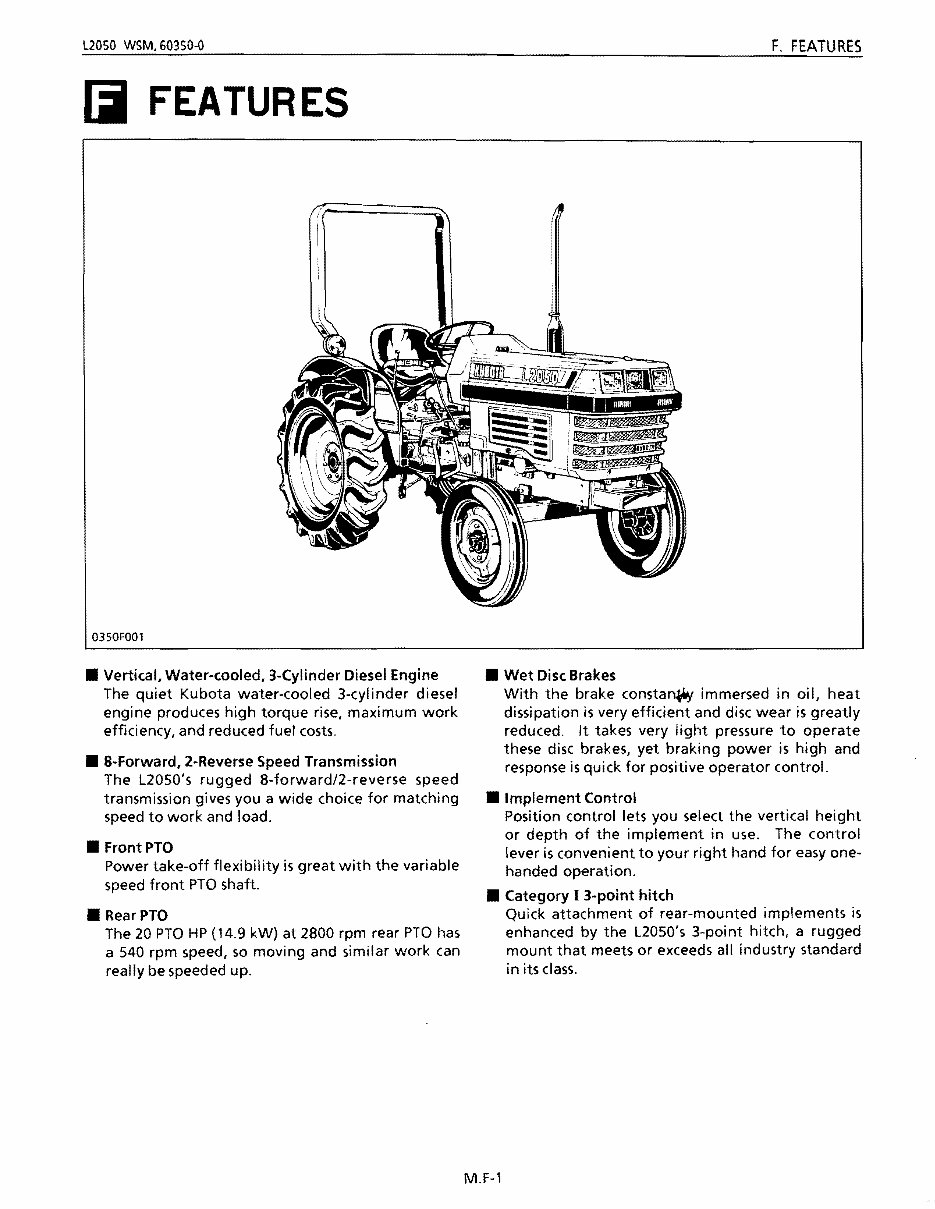
L2050 WSM.60350-O F. FEATURES iii FEA TUR ES 0350F001 • Vertical, Water-cooled, 3-Cylinder Diesel Engine The quiet Kubota water-cooled 3-cylinder diesel engine produces high torque rise, maximum work efficiency, and reduced fuel costs. • 8-Forward, 2-Reverse Speed Transmission The L2050's rugged 8-forward/2-reverse speed transmission gives you a wide choice for matching speed to work and load. • FrontPTO Power take-off flexibility is great with the variable speed front PTO shaft. • RearPTO The 20 PTO HP (14.9 kW) at 2800 rpm rear PTO has a 540 rpm speed, so moving and similar work can really be speeded up. • Wet Disc Brakes With the brake constani'Y immersed in oil, heat dissipation is very efficient and disc wear is greatly reduced. It takes very light pressure to operate these disc brakes, yet braking power is high and response is quick for positive operator control. • Implement Control Position control lets you select the vertical height or depth of the implement in use. The control lever is convenient to your right hand for easy one- handed operation. • Category I 3-point hitch Quick attachment of rear-mounted implements is enhanced by the L2050's 3-point hitch, a rugged mount that meets or exceeds all industry standard in its class. M.F-1
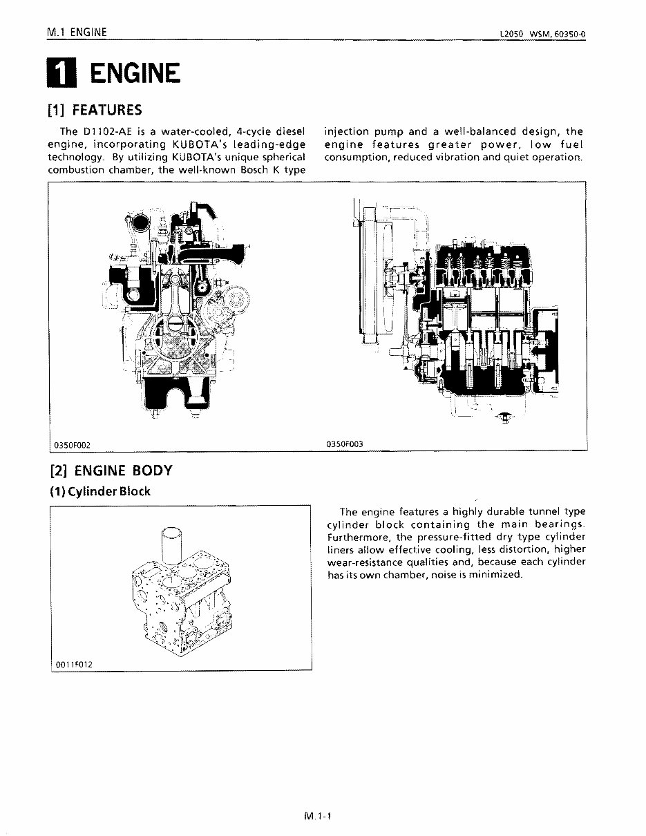
M.l ENGINE L2050 WSM,60350-0 D ENGINE [1] FEATURES The D 11 02-AE is a water-cooled, 4-cycle diesel injection pump and a well-balanced design, the engine, incorporating KUBOTA's leading-edge engine features greater power, low fuel technology. By utilizing KUBOTA's unique spherical consumption, reduced vibration and quiet operation. combustion chamber, the well-known Bosch K type 0350F002 0350F003 [2] ENGINE BODY (1) Cylinder Block 0011F012 The engine features a highly durable tunnel type cylinder block containing the main bearings. Furthermore, the pressure-fitted dry type cylinder liners allow effective cooling, less distortion, higher wear-resistance qualities and, because each cylinder has its own chamber, noise is minimized. M.l-l
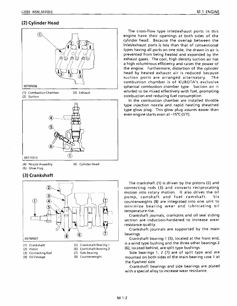
L2050 WSM.60350"{) M.1 ENGINE 0076F006 Combustion Chamber (3) Exhaust (2) Cylinder Head (1) (2) Suction (5) Glow Plug (3) Crankshaft (4) Oil Passage 0011F013 (4) Nozzle Assembly (6) Cylinder Head The cross-flow type inlet/exhaust ports in this engine have their openings at both sides of the cylinder head. Because the overlap between the inlet/exhaust ports is less than that of conventional types having all ports on one side, the drawn in air is prevented from being heated and expanded by thfl exhaust gases. The cool, high density suction air has a high voluminous efficiency and raises the power of the engine. Furthermore, distortion of the cylinder head by heated exhaust air is reduced because suction ports are arranged alternately. The combustion chamber is of KUBOTA's exclusive spherical combustion chamber type. Suction air is whirled to be mixed effectively with fuel, prompting combustion and reducing fuel consumption. In the combustion chamber are installed throttle type injection nozzle and rapid heating sheathed type glow plug. This glow plug assures easier than even engine starts even at -15°C (5°F). The crankshaft (1) is driven by the pistons (2) and connecting rods (3) and converts reciprocating motion into rotary motion. It also drives the oil pump, camshaft and fuel camshaft. Six counterweights (8) are integrated into one unit to minimize bearing wear and lubricating oil temperature rise. Crankshaft journals, crankpins and oil seal sliding section are induction-hardened to increase wear resistance quality. Crankshaft journals are supported by the main bearings. Crankshaft bearing 1 (5), located at the front end, is a wind type bushing and the three other bearings 2 (6), located behind, are split type bushings. Side bearings 1, 2 (7) are of split type and are mounted on both sides of the main bearing case 1 at the flywheel side. Crankshaft bearings and side bearings are plated with a special alloy to increase wear resistance. (1) Crankshaft (2) Piston (3) Connecting Rod (5) Crankshaft Bearing 1 (6) Crankshaft Bearing 2 (7) Side Bearing (8) Counterweight M.1-2
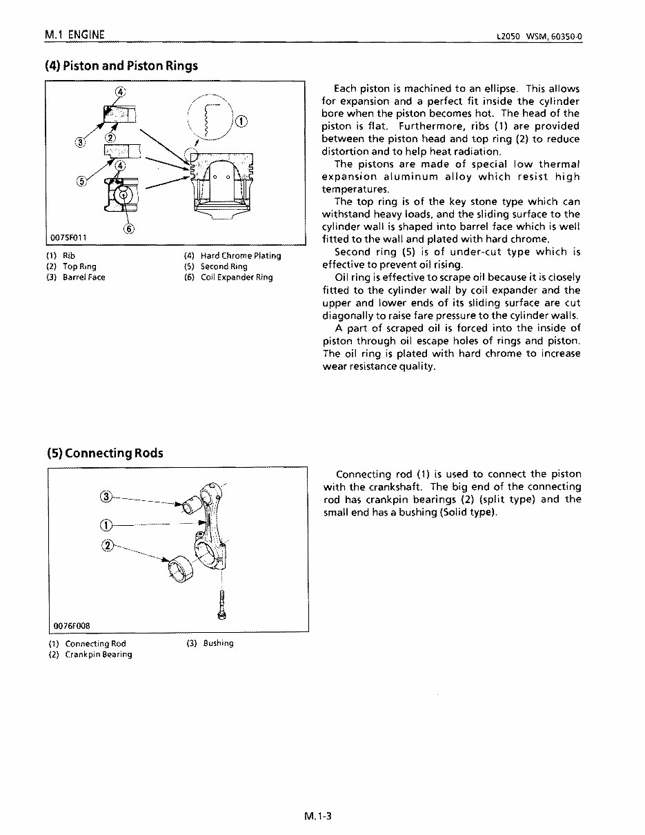
M.1 ENGINE L2050 WSM,60350-0 (4) Piston and Piston Rings (1) Rib (4) Hard Chrome Plating (2) Top Ring (5) Second Ring (3) Barrel Face (6) Coil Expander Ring (5) Connecting Rods (1) Connecting Rod (2) Crank pin Bearing 00 76FOO8 (3) Bushing Each piston is machined to an ellipse. This allows for expansion and a perfect fit inside the cylinder bore when the piston becomes hot. The head of the piston is flat. Furthermore, ribs (1) are provided between the piston head and top ring (2) to reduce distortion and to help heat radiation. The pistons are made of special low thermal expansion aluminum alloy which resist high temperatures. The top ring is of the key stone type which can withstand heavy loads, and the sliding surface to the cylinder wall is shaped into barrel face which is well fitted to the wall and plated with hard chrome. Second ring (5) is of under-cut type which is effective to prevent oil rising. Oil ring is effective to scrape oit because it is closely fitted to the cylinder wall by coil expander and the upper and lower ends of its sliding surface are cut diagonally to raise fare pressure to the cylinder walls. A part of scraped oil is forced into the inside of piston through oil escape holes of rings and piston. The oil ring is plated with hard chrome to increase wear resistance quality. Connecting rod (1) is used to connect the piston with the crankshaft. The big end of the connecting rod has crankpin bearings (2) (split type) and the small end has a bushing (Solid type). M.1-3
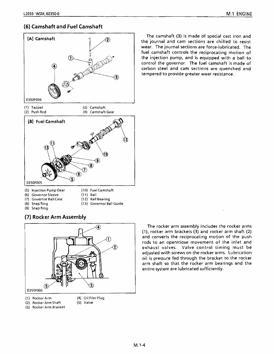
L2050 WSM,60350-O M.l ENGINE (6) Camshaft and Fuel Camshaft [A] camshaft 0350F004 (1) Tappet (3) Camshaft (2) Push Rod (4) Camshaft Gear [B] Fuel Camshaft 10 (5) Injection Pump Gear (10) Fuel Camshaft (6) Governor Sleeve (11) Ball (7) Governor Ball Case (12) Ball Bearing (8) Snap Ring (13) Governor Ball Guide (9) Snap Ring (7) Rocker Arm Assembly 5 0350FOO6 (1) RockerArm (4) Oil Filer Plug (2) Rocker Arm Shaft (5) Valve (3) Rocker Arm Bracket The camshaft (3) is made of special cast iron and the journal and cam sections are chilled to resist wear. The journal sections are force-lubricated. The fuel camshaft controls the reciprocating motion of thf? injection pump, and is equipped with a ball to control the governor. The fuel camshaft is made of carbon steel and cam sections are quenched and tempered to provide greater wear resistance. The rocker arm assembly includes the rocker arms (1), rocker arm brackets (3) and rocker arm shaft (2) and converts the reciprocating motion of the push rods to an open/close movement of the inlet and exhaust valves. Valve control timing must be adjusted with screws on the rocker arms. Lubrication oil is pressure fed through the bracket to the rocker arm shaft so that the rocker arm bearings and the entire system are lubricated sufficiently. M.1-4
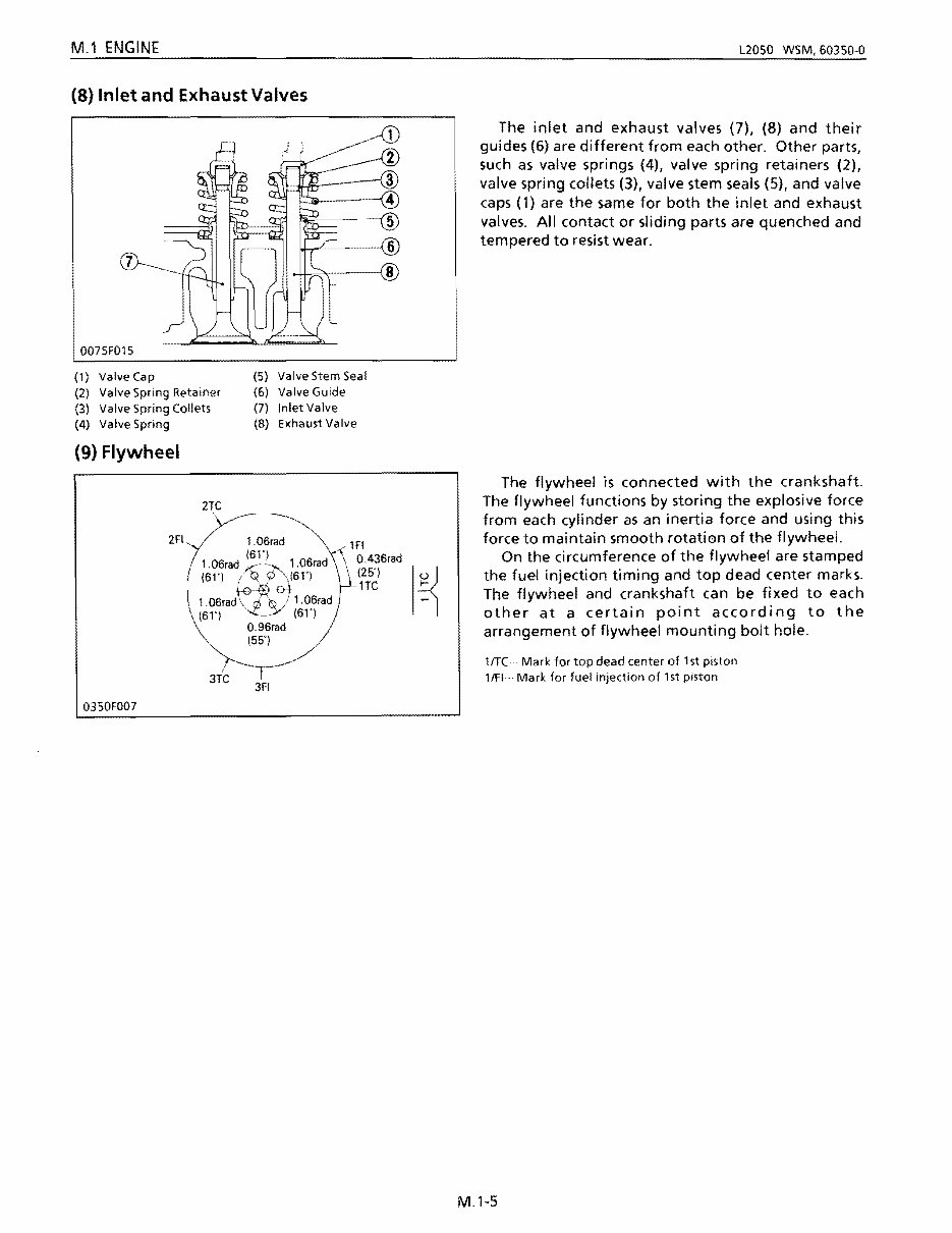
M.1 tNGINt L2050 WSM.60350-0 (8) Inlet and Exhaust Valves 0075F015 (1) Valve Cap (5) Valve Stem Seal (2) Valve Spring Retainer (6) Valve Guide (3) Valve Spring Collets (7) Inlet Valve (4) Valve Spring (8) Exhaust Valve (9) Flywheel 2TC 2FI 1.06rad lF! (6n OA36rad 1.06rad X-~. i .06rad (25") (61') {V \(6n 1.06rad~of 1.06rad HC (61') '..c~y (61') O.96rad (55") 0350F007 The inlet and exhaust valves (7)' (8) and their guides (6) are different from each other. Other parts, such as valve springs (4), valve spring retainers (2), valve spring collets (3), valve stem seals (5), and valve caps (1) are the same for both the inlet and exhaust valves. All contact or sliding parts are quenched and tempered to resist wear. The flywheel is connected with the crankshaft. The flywheel functions by storing the explosive force from each cylinder as an inertia force and using this force to maintain smooth rotation of the flywheel. On the circumference of the flywheel are stamped the fuel injection timing and top dead center marks. The flywheel and crankshaft can be fixed to each other at a certain point according to the arrangement of flywheel mounting bolt hole. lfTC .. · Mark for top dead center of 15t piston lfFI· Mark for fuel injection of 15t piston M.1-5
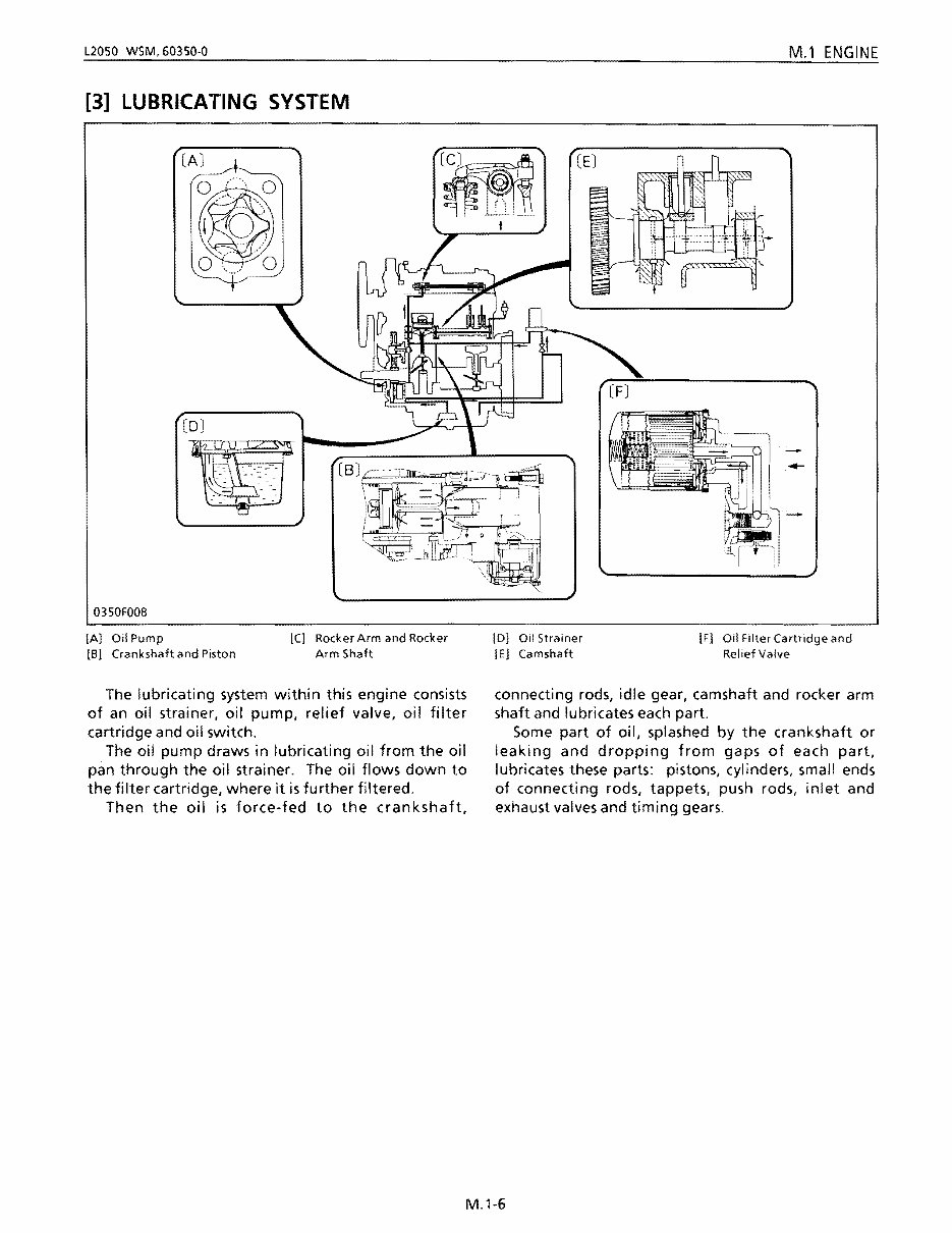
L2050 W$M,60350-0 M.1 ENGINE [3] LUBRICATING SYSTEM C.J . @I n [0] 0350F008 t [A] OilPump [C] Rocker Arm and Rocker [8) Crankshafhnd Piston Arm Shaft The lubricating system within this engine consists of an oil strainer, oil pump, relief valve, oil filter cartridge and oil switch. The oil pump draws in lubricating oil from the oil pan through the oil strainer. The oil flows down to the filter cartridge, where it is further filtered. Then the oil is force-fed to the crankshaft, [D) Oil Strainer [F] Oil Filter Cartridge and [E) Camshaft Relief Valve connecting rods, idle gear, camshaft and rocker arm shaft and lubricates each part. Some part of oil, splashed by the crankshaft or leaking and dropping from gaps of each part, lubricates these parts: pistons, cylinders, small ends of connecting rods, tappets, push rods, inlet and exhaust valves and timing gears. M.1-6
This workshop service manual for the Kubota L2050 Tractor Service & Repair Manual is designed for mechanical technicians familiar with service procedures for Kubota products. It covers repair and overhaul of the Kubota L2050 Tractor with detailed instructions on components manufactured for this model and repair procedures for proprietary components. The manual provides reliable information and highlights important safety information and cautions, with warnings, cautions, and notes clearly noted throughout.
The manual offers step-by-step diagnostic and repair procedures, making it an essential resource for both professional mechanics and DIY enthusiasts. It emphasizes the critical importance of safety equipment and precautions when working on the Kubota L2050 Tractor, including guidelines for using a torque wrench and other special tools for adjustments or repairs.
By owning and referring to this manual, Kubota L2050 Tractor owners will be better informed and equipped to perform repairs with the expertise of a professional automotive technician. It includes comprehensive instructions for a wide range of repairs, from routine tune-ups and general maintenance to complex removal, installation procedures, assemblies, disassemblies, fuel system, ignition, lubrication system, exhaust, electrical system, and extensive engine and transmission disassembly procedures.
This complete service manual is delivered electronically via email for fast and free access. The content accurately depicts parts and procedures applicable to the Kubota L2050 Tractor Service & Repair Manual at the time of writing.
Language: English
Printable: Yes
File Format: .PDF
The manual also includes general maintenance tags for various components and systems, such as air cleaner element renewal, battery terminal check, brake hydraulic fluid renewal, engine coolant renewal, exhaust system check, fluid level checks, front and rear brake pad/shoe check, gearbox oil level check, road test, spark plug check and renewal, timing belt renewal, tyre checks, and more.