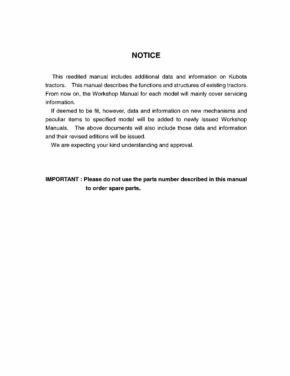
2-M1 TRACTOR, WSM CLUTCH 1. DRY TYPE, SINGLE PLATE CLUTCH ■ Clutch “Engaged” When the clutch pedal is not depressed, the clutch release bearing (9) and the fingers of diaphragm spring (5) are not connected to each other. Accordingly, the pressure plate (4) is tightly pressed against the flywheel (1) by the diaphragm spring (5). As a result, rotation of the flywheel (1) is transmitted to the transmission through the clutch shaft (10) due to the frictional force among the flywheel (1), clutch disc (2) and pressure plate (4). W10126980 ■ Clutch “Disengaged” When the clutch pedal is depressed, the clutch pedal rod is pulled to move the clutch rod (7). Then, the release fork (6) pushes the release hub (8) and release bearing (9) toward the flywheel. Simultaneously, the release bearing (9) pushes the diaphragm spring (5). As the pressure plate (4) is pulled by the diaphragm spring (5), the frictional force among the flywheel (1), clutch disc (2) and pressure plate (4) disappears. Therefore, rotation of the flywheel (1) is not transmitted to the clutch disc (2), and then the rotation of the clutch shaft (10) stops. W10129450 (1) Flywheel (2) Clutch Disc (3) Clutch Cover (4) Pressure Plate (5) Diaphragm Spring (6) Release Fork (7) Clutch Rod (8) Release Hub (9) Release Bearing (10) Clutch Shaft (1) Flywheel (2) Clutch Disc (3) Clutch Cover (4) Pressure Plate (5) Diaphragm Spring (6) Release Fork (7) Clutch Rod (8) Release Hub (9) Release Bearing (10) Clutch Shaft KiSC issued 06, 2006 A
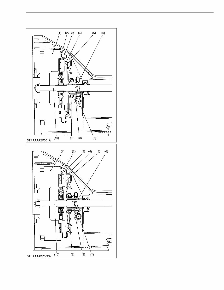
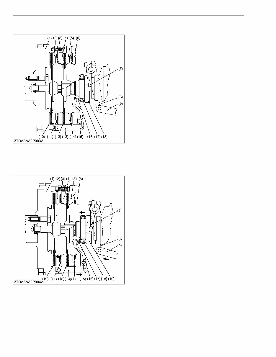
2-M2 TRACTOR, WSM CLUTCH 2. DRY TYPE, DUAL STAGE CLUTCH A dual stage clutch is a combination of two single plate clutches. One clutch controls power transmitted to travelling, and the other to the PTO. ■ Travelling Clutch “Engaged” ■ PTO Clutch “Engaged” When the clutch pedal is not depressed, there is a certain amount of clearance between the release bearing (17) and the adjusting screw (16) mounted on the release lever (15). Under the conditions above; • The travelling clutch disc (10) is pressed between the flywheel (1) and the pressure plate 1 (2) by the force of the belleville spring (11). • The PTO clutch disc (12) is pressed between the clutch cover 1 (4) and the pressure plate 2 (5) by the force of the belleville spring (14). Thus, the rotation of flywheel is transmitted to both the travelling and PTO systems. W10128590 ■ Travelling Clutch “Disengaged” ■ PTO Clutch “Engaged” When the clutch pedal is depressed to the middle of the stroke, the clutch rod (9) is pushed to move the clutch lever (8). Then, the release fork (7) pushes the release hub (19) and release bearing (18) toward the flywheel. Simultaneously, the release bearing (18) pushes the adjusting screw (17) attached to the release lever (16). The release lever pulls the pressure plate 1 (2) by means of the release rod (13) as the lever turns at the clevis pin (15) as a fulcrum. When the pressure plate 1 is pulled, friction force among the clutch cover 1 (4), clutch disc (10) and the pressure plate 1 (2) is lost. The rotation of flywheel is not transmitted to travelling system. At this time, the pressure plate 2 (5) is in contact with the head of the adjusting screw (3) which serves as a stopper. W10133220 (1) Flywheel (2) Pressure Plate 1 (Travelling) (3) Adjusting Screw (4) Clutch Cover 1 (5) Pressure Plate 2 (PTO) (6) Clutch Cover 2 (7) Release Fork (8) Clutch Lever (9) Clutch Rod (10) Clutch Disc (Travelling) (11) Belleville Spring (12) Clutch Disc (PTO) (13) Release Rod (14) Belleville Spring (15) Release Lever (16) Adjusting Screw (17) Release Bearing (18) Release Hub (1) Flywheel (2) Pressure Plate 1 (Travelling) (3) Adjusting Screw (4) Clutch Cover 1 (5) Pressure Plate 2 (PTO) (6) Clutch Cover 2 (7) Release Fork (8) Clutch Lever (9) Clutch Rod (10) Clutch Disc (Travelling) (11) Belleville Spring (12) Clutch Disc (PTO) (13) Release Rod (14) Belleville Spring (15) Clevis Pin (16) Release Lever (17) Adjusting Screw (18) Release Bearing (19) Release Hub KiSC issued 06, 2006 A
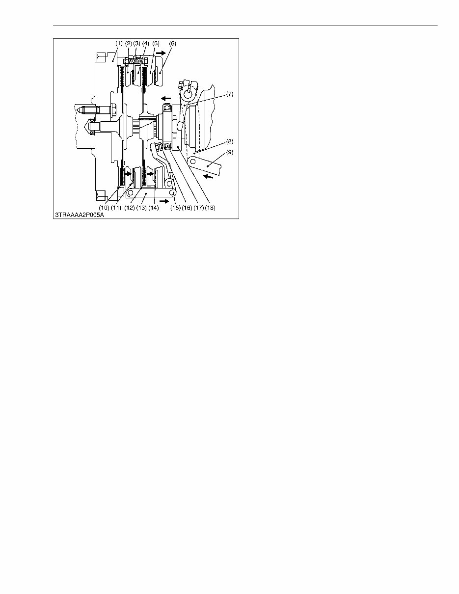
2-M3 TRACTOR, WSM CLUTCH ■ Travelling Clutch “Disengaged” ■ PTO Clutch “Disengaged” When the clutch pedal is depressed to the full stroke, the pressure plate 2 (5) is pushed to the right by the adjusting screw (3). This results in no friction among the flywheel (1), clutch disc (12) and pressure plate 2 (5). The rotation of flywheel is not transmitted to PTO system and travelling system. W10139990 (1) Flywheel (2) Pressure Plate 1 (Travelling) (3) Adjusting Screw (4) Clutch Cover 1 (5) Pressure Plate 2 (PTO) (6) Clutch Cover 2 (7) Release Fork (8) Clutch Lever (9) Clutch Rod (10) Clutch Disc (Travelling) (11) Belleville Spring (12) Clutch Disc (PTO) (13) Release Rod (14) Belleville Spring (15) Release Lever (16) Adjusting Screw (17) Release Bearing (18) Release Hub KiSC issued 06, 2006 A
This is a comprehensive factory service repair manual for the Kubota All Tractor - MECHANISM. The manual contains easy-to-read text sections with high-quality diagrams and instructions, making it suitable for both do-it-yourselfers and experienced mechanics. It includes step-by-step instructions, detailed exploded pictures, and diagrams to effectively complete the required tasks. The Kubota All Tractor - MECHANISM Service Repair Workshop Manual covers every detail of the machine and provides servicing and maintenance information based on complete disassembly of the machine.
The manual is an inexpensive way to ensure the proper functioning of your vehicle. It covers various models and includes the following:
Kubota All Tractor - MECHANISM
The Service Repair Manual covers:
General information
Periodic maintenance
Engine
Fuel system and throttle body
Cooling and lubrication system
Chassis
Electrical system
Servicing information
Emission control information
Wiring diagram
And more
This professional technical manual contains service, maintenance, and troubleshooting information for your Kubota All Tractor - MECHANISM, covering all models, engines, trims, and transmission types. It is a top-quality Workshop Repair Service manual that is complete and intact without any missing or corrupt parts or pages. The manual is the same as the one used in local service/repair shops and is guaranteed to be fully functional, saving you time.
The file format is PDF, and the language is English. It is printable without any restrictions and requires Adobe Reader. Upon payment completion, the download link will appear on the checkout page. Payments can be made via PayPal or Credit Card, and the download link will be available instantly.
Recently Viewed
5,521,897Happy Clients
2,594,462eManuals
1,120,453Trusted Sellers
15Years in Business
Price:
Actual Price:
Kubota All Tractor - Mechanism Service Repair Manual