Kioti Daedong RX6010C, RX6010PC Tractors OEM Service & Repair Manual
What's Included?
Lifetime Access
Fast Download Speeds
Offline Viewing
Access Contents & Bookmarks
Full Search Facility
Print one or all pages of your manual
TABLE OF CONTENTS ENGINE RX6010C(PC) CHAPTER 3 1. ENGINE IDENTIFICATION...................... 3-3 1.1 Engine EPA decal (A) ................................ 3-3 1.2 Engine number (B) .................................... 3-3 1.3 Assignment standard for engine model code .. 3-4 2. SPECIFICATIONS ................................... 3-5 2.1 General specifications ............................... 3-5 2.2 Engine performance curve ........................ 3-6 2.3 Engine performance curve analysis .......... 3-7 2.4 Servicing specifications ............................. 3-9 3. OPERATING PRINCIPLE...................... 3-14 3.1 Body and power train system .................. 3-14 3.2 Lubricating system .................................. 3-18 3.3 Cooling system ........................................ 3-22 3.4 Fuel system ............................................. 3-25 3.4.1 Fuel flow route ............................ 3-25 3.4.2 Fuel filter ..................................... 3-26 3.4.3 Bleeding the fuel system ............ 3-26 3.4.4 Fuel feed pump........................... 3-26 3.4.5 Fuel injection pump .................... 3-27 3.4.6 Injection Nozzle .......................... 3-29 3.4.7 CTD pump .................................. 3-30 3.5 Governor and stop system ...................... 3-31 3.5.1 Basic principle of governor system .. 3-31 3.5.2 Operation of Governor ................ 3-32 3.6 Turbo charger .......................................... 3-33 3.7 Internal egr system for turbo enginE ....... 3-34 3.8 FAS reduction system for turbo engine ...3-35 3.9 Limiter for fas reduction system .............. 3-37 4. TROUBLESHOOTING .......................... 3-38 5. MEASUREMENT AND ADJUSTMENT. 3-41 5.1 Fan belt ................................................... 3-41 5.2 Piston compression pressure measurement .. 3-41 5.3 Valve clearance ....................................... 3-42 5.4 Valve lift (Deflection and worn condition of valve cam, tappet, push rod, rocker arm, etc.) .........3-43 5.5 Injection timing measurement and adjustment.... 3-44 5.6 Oil pressure measurement ...................... 3-45 5.7 Bubble test for radiator ............................ 3-46 5.8 Injection nozzle Inspection ...................... 3-46 5.9 Turbo charger wastegate pressure check ..3-47 6. EXPLODED VIEW ................................. 3-48 6.1 E010 cylinder block ................................. 3-48 6.2 E020 oil pan ............................................ 3-49 6.3 E030 cylinder head.................................. 3-50 6.4 E040 gear case ....................................... 3-51 6.5 E050 main bearing case.......................... 3-52 6.6 E 080 valve rocker arm ........................... 3-53 6.7 E030 cylinder head cover ........................ 3-54 6.8 E100 camshaft ........................................ 3-55 6.9 E110 piston crankshaft ............................ 3-56 6.10 E120 flywheel .......................................... 3-57 6.11 E130 nozzle holder.................................. 3-58 6.12 E140 fuel camshaft ................................. 3-59 6.13 E150 speed control plate ........................ 3-60 6.14 E160 engine stop lever ............................ 3-61 6.15 E075 boost .............................................. 3-62 영M55(RX6010)_03장_엔진.indd 1 2011-11-01 오후 5:35:57
TABLE OF CONTENTS 6.16 E170 Governor ...................................... 3-63 6.17 E180 Water pump.................................. 3-64 6.18 E190 Coolant pipe ................................. 3-65 6.19 E200 AC generator ................................ 3-66 6.20 E220 Manifold ....................................... 3-67 6.21 E070 Turbo ............................................ 3-68 7. DISASSEMBLY, SERVICE AND ASSEMBLY.. 3-69 7.1 Engine removal ....................................... 3-69 7.2 Head cover .............................................. 3-78 7.3 Head cover installation ............................ 3-79 7.4 Glow plug and fuel overflow pipe.................. 3-79 7.5 Heat seal Removal .................................. 3-80 7.6 Rocker arm assembly.............................. 3-81 7.6.1 Removal and installation ............ 3-81 7.6.2 Rocker arm assembly check ...... 3-82 7.7 Cylinder head .......................................... 3-83 7.7.1 Cylinder head removal................ 3-83 7.7.2 Cylinder head installation ........... 3-84 7.7.3 Cylinder head surface flatness check.. 3-84 7.8 Intake and exhaust valves ....................... 3-85 7.8.1 Valve Removal ............................ 3-85 7.8.2 Valve Installation......................... 3-85 7.8.3 Valve recess check ..................... 3-85 7.8.4 Valve seat check......................... 3-86 7.8.5 Valve spring check...................... 3-86 7.8.6 Valve spring squareness (Tilt) .... 3-87 7.9 Injection pump ......................................... 3-87 7.9.1 Injection pump Removal ............. 3-87 7.9.2 Injection pump Installation .......... 3-88 7.9.3 Injection pump disassembly ....... 3-88 7.9.4 Nozzle holder disassembly ......... 3-89 7.9.5 FAS reduction system (Booster) disassembly ................................ 3-89 7.10 Governor spring and stop solenoid ....... 3-90 7.11 Gear case .............................................. 3-91 7.12 Idle gear and crank gear ....................... 3-92 7.13 Valve camshaft ...................................... 3-93 7.14 Fuel camshaft ........................................ 3-94 7.15 Crank gears and shafts check ............... 3-94 7.15.1 Timing gear backlash ................ 3-94 7.15.2 Idle gear side clearance ............ 3-94 7.15.3 Valve camshaft gear side clearance ..... 3-95 7.15.4 Fuel camshaft gear side clearance ..... 3-95 7.15.5 Idle gear oil clearance measurement .. 3-95 7.15.6 idle gear bushing replacement ....3-95 7.15.7 Valve camshaft oil clearance measurement .. 3-96 7.15.8 Valve Camshaft deflection check.. 3-96 7.15.9 Valve Cam height measurement .. 3-96 7.16 Piston and connecting rod.................... 3-97 7.17 Piston and connecting rod check ................ 3-98 7.17.1 Piston pin bore .......................... 3-98 7.17.2 piston pin and bushing Clearance.... 3-99 7.17.3 piston pin bushing replacement ..... 3-99 7.18 Piston ring measurement ..................... 3-99 7.18.1 Piston ring end gap ................... 3-99 7.18.2 Piston ring clearance............... 3-100 7.19 Crankshaft and flywheel ..................... 3-100 7.20 Metal journal bearings ........................ 3-104 7.21 Flywheel and crankshaft check ............. 3-105 7.21.1 Flywheel deflection and crankshaft end play ............... 3-105 7.21.2 Crankshaft deflection .............. 3-105 7.21.3 Crankshaft journal and bearing 1 oil clearance.. 3-105 7.21.4 Crankshaft metal bearing 1 replacement .. 3-106 7.21.5 Crankshaft journal and bearing 2 oil clearance .. 3-106 7.21.6 Ccrank pin and connecting rodbearing 2 Oil clearance ............................... 3-107 7.22 Cylinder bore check ........................... 3-107 7.23 Oil pump, oil filter, relief valve and oil strainer . 3-108 7.23.1 Relief valve of engine oil ......... 3-108 7.23.2 Oil pump check ....................... 3-108 7.24 Thermostat ......................................... 3-109 7.25 Water pump ........................................ 3-110 7.26 Turbo charger ..................................... 3-110 영M55(RX6010)_03장_엔진.indd 2 2011-11-01 오후 5:35:58
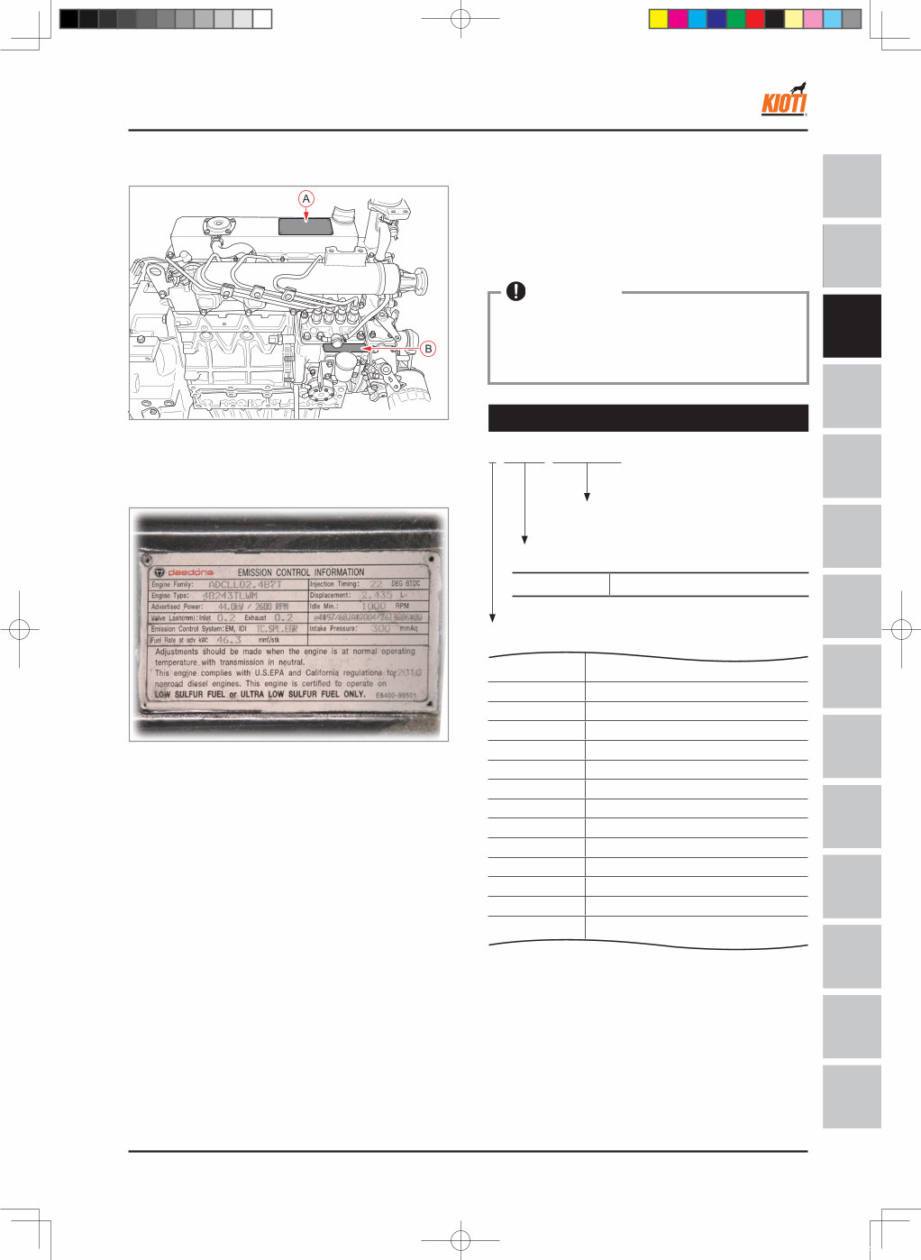
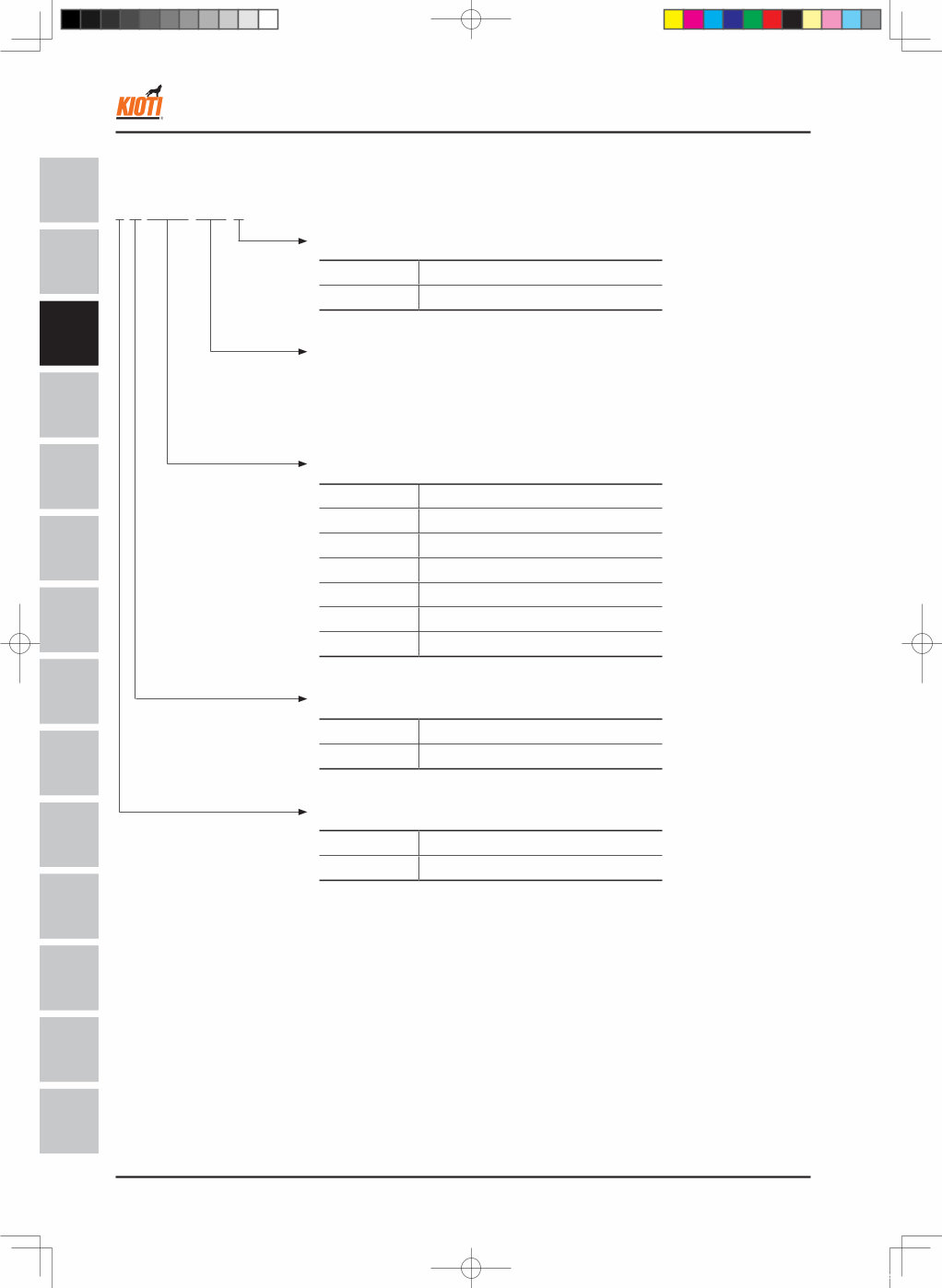
DH80-W00 Aug. 2011 3 -3 SAFETY FIRST GENERAL ENGINE CLUTCH TRANSMI SSION HST REAR AXLE BRAKE FRONT AXLE STEERING SYSTEM HYDRAULIC SYSTEM ELECTRIC SYSTEM CABIN A/C AND HEATER SAFETY FIRST GENERAL ENGINE CLUTCH TRANSMISSION REAR AXLE BRAKE FRONT AXLE STEERING SYSTEM HYDRAULIC SYSTEM ELECTRIC & CALIBRATION CABIN A/C & HEATER INDEX RX6010C(PC) 1. ENGINE IDENTIFICATION T46W201B 1.2 ENGINE NUMBER (B) The engine number is stamped near the fuel injection pump on the cylinder block, and the bar code is at- tached on the intake manifold. The engine number is necessary information that is requested on the warranty registration form. This number should be on the form as well as the tractor number and the amount of time used. • For example, KK1400001 means that this engine is the first manufactured unit, 4B243TLWM, in 2010. K K 1 4 0 0 0 0 1 Serial number Engine model Year of manufacturing K14 4B243TLWM � � � � 1 2001 2 2002 3 2003 D 2004 E 2005 F 2006 G 2007 H 2008 J 2009 K 2010 L 2011 M 2012 � � � � Engine number assignment standard IMPORTANT H80W301A 1.1 ENGINE EPA DECAL (A) This aluminum decal is riveted on the engine cylinder head cover. This provides the information such as model number, displacement, rated output, valve clear- ance, injection timing, etc. This decal represents that this engine is in compliance with the U.S.EPA and California (CARB) exhaust emis- sion regulation. ENGINE - ENGINE IDENTIFICATION 영M55(RX6010)_03장_엔진.indd 3 2011-11-01 오후 5:36:03
3 -4 DH80-W00 Aug. 2011 SAFETY FIRST GENERAL ENGINE CLUTCH TRANSMI SSION HST REAR AXLE BRAKE FRONT AXLE STEERING SYSTEM HYDRAULIC SYSTEM ELECTRIC SYSTEM CABIN A/C AND HEATER SAFETY FIRST GENERAL ENGINE CLUTCH TRANSMISSION REAR AXLE BRAKE FRONT AXLE STEERING SYSTEM HYDRAULIC SYSTEM ELECTRIC & CALIBRATION CABIN A/C & HEATER INDEX RX6010C(PC) 1.3 ASSIGNMENT STANDARD FOR ENGINE MODEL CODE 4 B 2 4 3 TLW M Mechanical or HST D, B, A, M Mechanical E, H HST Turbo and Tier4 type 139 Approx. 1,390 cc 150 Approx. 1,500 cc 165 Approx. 1,650 cc 183 Approx. 1,830 cc 200 Approx. 2,000 cc 220 Approx. 2,200 cc 243 Approx. 2,430 cc Displacement A 92.4 mm (3.638 in.) B 102.4 mm (4.031 in.) Stroke 3 3 cylinders 4 4 cylinders Number of cylinders ENGINE - ENGINE IDENTIFICATION 영M55(RX6010)_03장_엔진.indd 4 2011-11-01 오후 5:36:03
DH80-W00 Aug. 2011 3 -5 SAFETY FIRST GENERAL ENGINE CLUTCH TRANSMI SSION HST REAR AXLE BRAKE FRONT AXLE STEERING SYSTEM HYDRAULIC SYSTEM ELECTRIC SYSTEM CABIN A/C AND HEATER SAFETY FIRST GENERAL ENGINE CLUTCH TRANSMISSION REAR AXLE BRAKE FRONT AXLE STEERING SYSTEM HYDRAULIC SYSTEM ELECTRIC & CALIBRATION CABIN A/C & HEATER INDEX RX6010C(PC) 2. SPECIFICATIONS 2.1 GENERAL SPECIFICATIONS Tractor model RX6010C(PC) Engine model 4B243TLWM(-K) Bore I.D. X Stroke mm(in.) Ø 87 × 102.4 (3.4 x 4.0) Honing Plateau honing Number of cylinders 4 Ignition sequence 1-3-4-2 Displacement ℓ(cu in.) 2.435 (148.6) Max./Min. speed (rpm) 2,800 / 1,000 Max. gross output kw(HP)/rpm. 44 (59) / 2,600 Max. torque Nm(kgf·m)/rpm 159.7 (16.3) / 1,700 Compression ratio 21.4 : 1 Combustion chamber type Indirect injection type (Swirl chamber) Turbo charged Injection timing (BTDC) 22° Fuel injection pump type BOSCH K MINI (CTD) Injection pressure kPa(kgf/cm 2 ) 14,700~15,680 (150 ~ 160) Engine oil capacity ℓ (u.s.gal.) 7.7 (2.034) Engine oil specification SAE 15W 40, CD or higher of API grade Coolant capacity ℓ (u.s.gal.) 9.1 (2.4) Anti-freeze Ethylene glycol 50% with anti-corrosive agent The engine gross output is measured with the cooling fan removed. The cylinder number for ignition sequence is given from the cylinder on the engine cooling fan side. If the coolant level drops due to its evaporation, add only water. If the coolant lever drops due to the leakage, add coolant mixed with anti-freeze. The freezing point of the 50% coolant mixture is -37°C (-34°F) in a normal condition. When replacing the coolant with a different type of coolant, flush the cooling system thoroughly beforehand. • • • • • ENGINE - SPECIFICATIONS 영M55(RX6010)_03장_엔진.indd 5 2011-11-01 오후 5:36:04
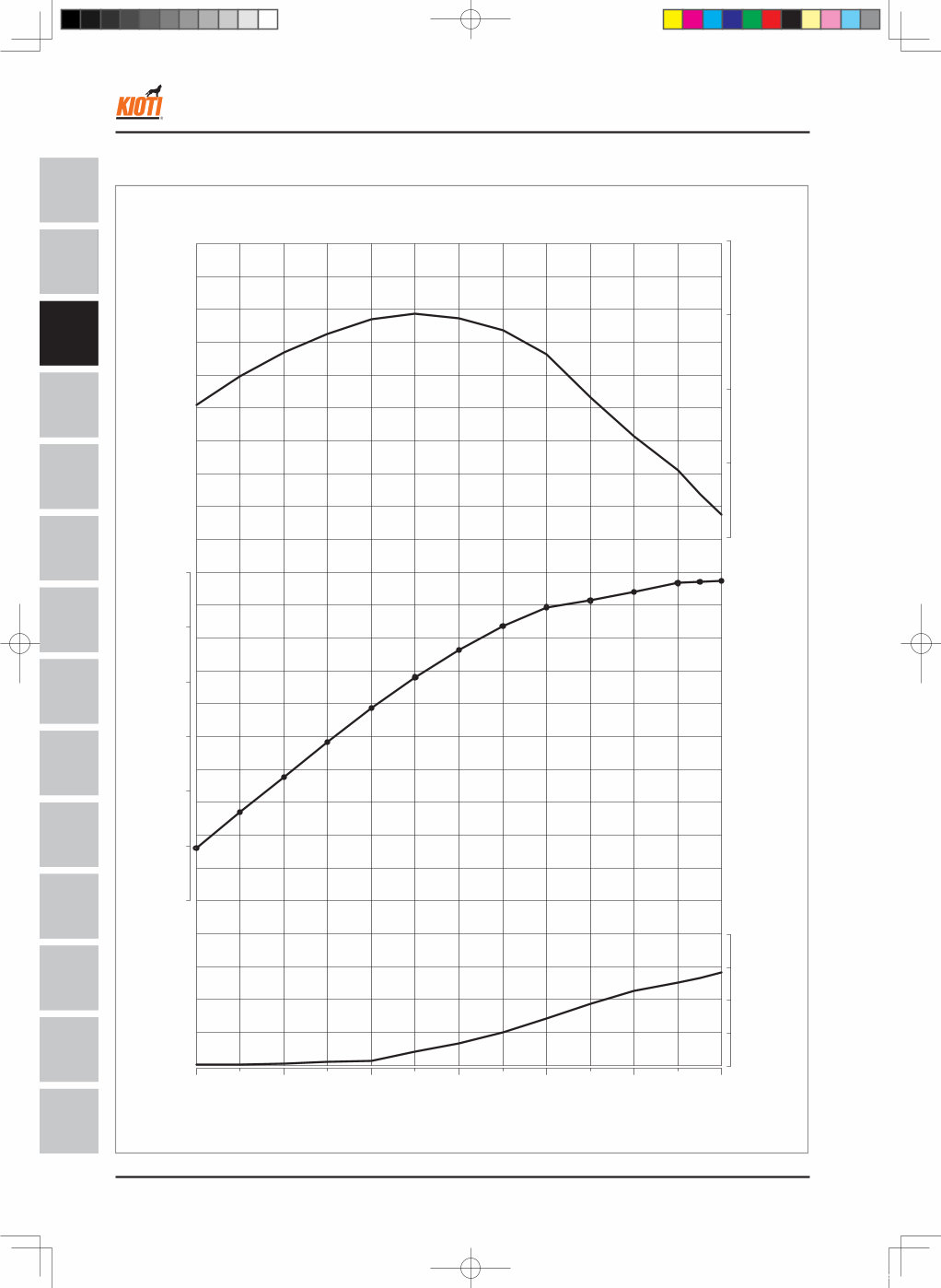
3 -6 DH80-W00 Aug. 2011 SAFETY FIRST GENERAL ENGINE CLUTCH TRANSMI SSION HST REAR AXLE BRAKE FRONT AXLE STEERING SYSTEM HYDRAULIC SYSTEM ELECTRIC SYSTEM CABIN A/C AND HEATER SAFETY FIRST GENERAL ENGINE CLUTCH TRANSMISSION REAR AXLE BRAKE FRONT AXLE STEERING SYSTEM HYDRAULIC SYSTEM ELECTRIC & CALIBRATION CABIN A/C & HEATER INDEX RX6010C(PC) 2.2 ENGINE PERFORMANCE CURVE 180 190 200 210 220 30 35 40 45 50 55 60 16 17 18 19 20 1400 1600 1800 2000 2200 2400 2600 Eng. Speed, rpm TORQUE (kgf·m) S.F.C (g/HPh) POWER (HP) H80W302A ENGINE - SPECIFICATIONS 영M55(RX6010)_03장_엔진.indd 6 2011-11-01 오후 5:36:05
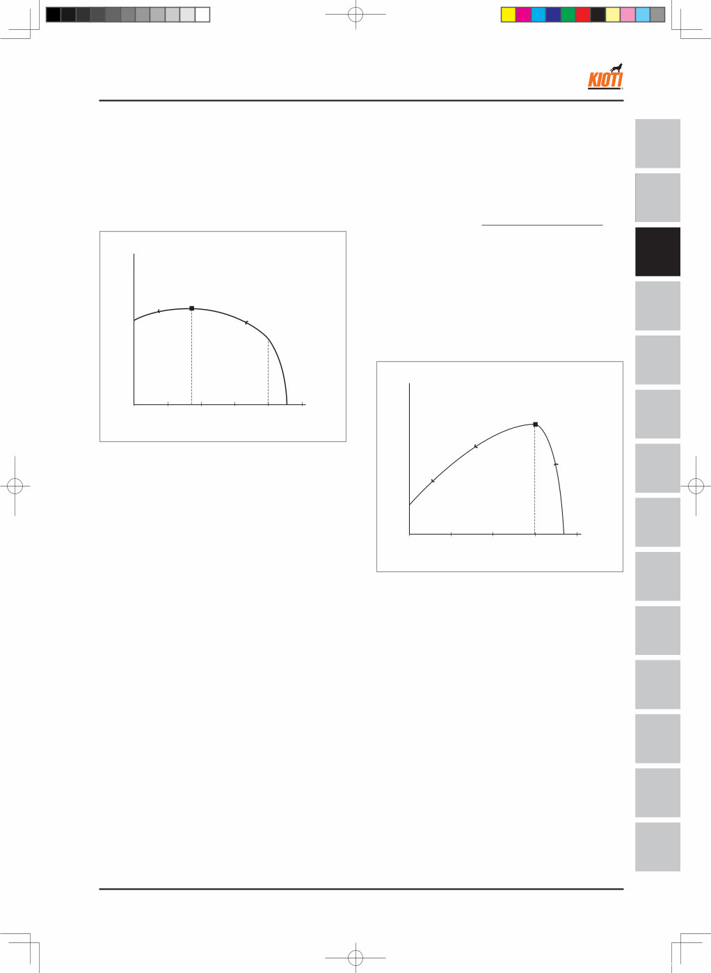
DH80-W00 Aug. 2011 3 -7 SAFETY FIRST GENERAL ENGINE CLUTCH TRANSMI SSION HST REAR AXLE BRAKE FRONT AXLE STEERING SYSTEM HYDRAULIC SYSTEM ELECTRIC SYSTEM CABIN A/C AND HEATER SAFETY FIRST GENERAL ENGINE CLUTCH TRANSMISSION REAR AXLE BRAKE FRONT AXLE STEERING SYSTEM HYDRAULIC SYSTEM ELECTRIC & CALIBRATION CABIN A/C & HEATER INDEX RX6010C(PC) 2.3 ENGINE PERFORMANCE CURVE ANALYSIS When running the engine at full speed without load, the engine rotates at approx. 2,800 rpm as shown in the figure. When the resistance is applied to the flywheel by braking with some kind of dynomometer, the rotating force of the dynomometer increases (arrow direction) as shown in the figure. In this case, the engine speed gradually decreases. When the engine speed reaches approx. 1,700 rpm, the torque starts to decrease. In other words, this point (1,700 rpm) is the maximum torque point. 1400 1800 2200 2600 3000 rpm (kg f -m) T46W207A Torque (kg f - m) Max. torque point 1400 1800 2200 2600 3000 최대 출력점 출력 (HP) rpm T46W208A Max. power point Power (HP) A. TORQUE When applying the rotating resistance to the fly- wheel, the engine speed drops and the rotating force of flywheel increases. Torque curve shows this force as a graph. B. BRAKE HORSE POWER (HP) The power is proportional to the rotating force (torque) and the rotating speed (RPM). Its formula is as follows: If substituting the torque and RPM in the left figure for the above formula and getting the power value, the below curve is provided. As shown in the below figure, when the power reaches the maximum point at 2,600 rpm, the power starts to drop. This is because the rpm drops sharply even the torque increases gradually. Power (HP) = Torque (Kg f - m) × rpm W 1kw = 1.341 HP ENGINE - SPECIFICATIONS 영M55(RX6010)_03장_엔진.indd 7 2011-11-01 오후 5:36:07
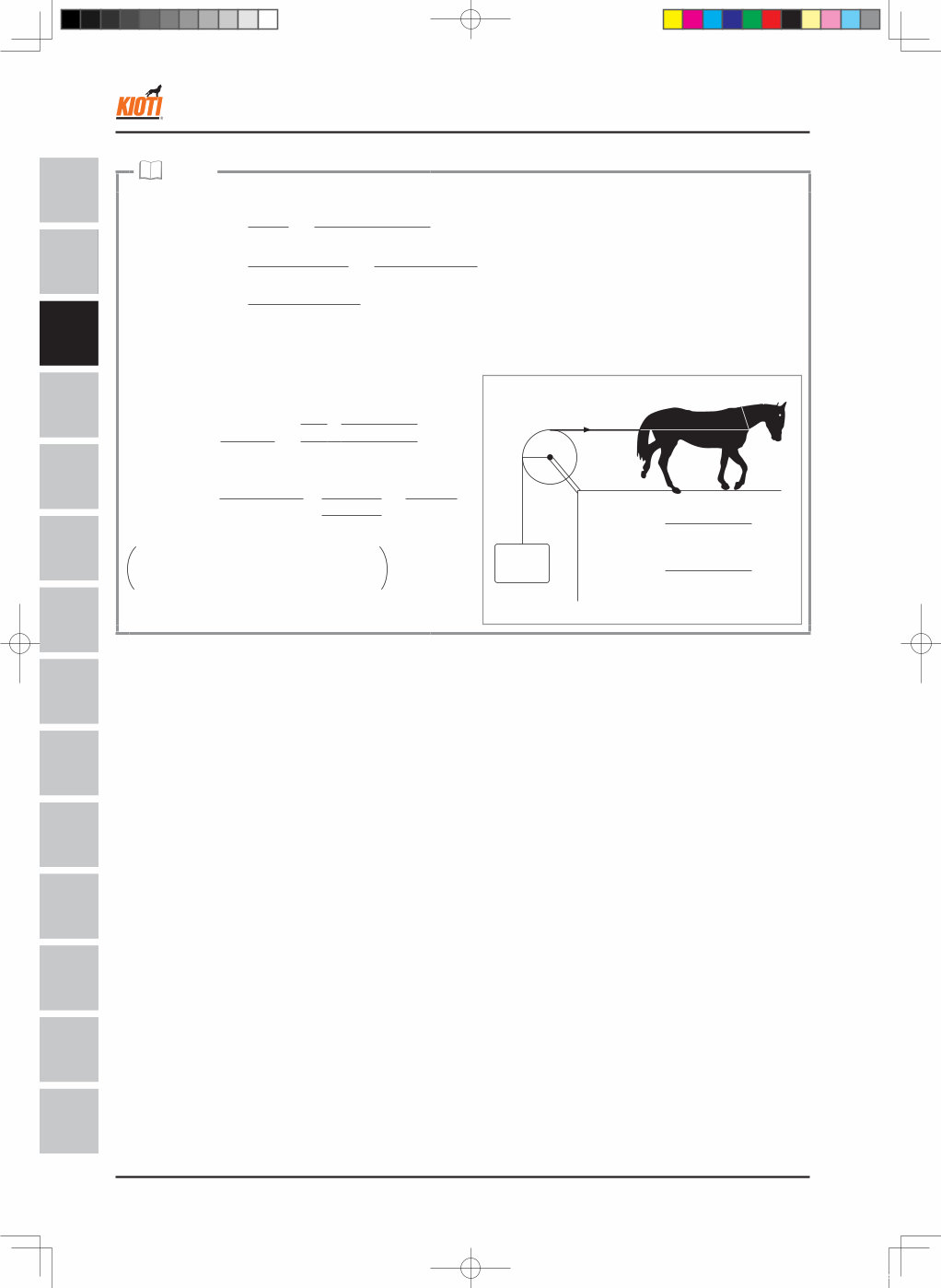
3 -8 DH80-W00 Aug. 2011 SAFETY FIRST GENERAL ENGINE CLUTCH TRANSMI SSION HST REAR AXLE BRAKE FRONT AXLE STEERING SYSTEM HYDRAULIC SYSTEM ELECTRIC SYSTEM CABIN A/C AND HEATER SAFETY FIRST GENERAL ENGINE CLUTCH TRANSMISSION REAR AXLE BRAKE FRONT AXLE STEERING SYSTEM HYDRAULIC SYSTEM ELECTRIC & CALIBRATION CABIN A/C & HEATER INDEX RX6010C(PC) C. S.F.C (SPECIFIC FUEL CONSUMPTION) The unit used here is "g/kW-hr". For example, 270g/kW-hr means that 270g of fuel is consumed by 1kW when running the engine for 1 hour. This can be converted as follows: Since the fuel consumption at full power in the power curve (4B243T) is 270g/kW-hr, the fuel consumption for 43.9kW is 270g x 43.9/hr = 11.85kg/hr. When converting this value to volume value, 11.85 ÷ 0.835 ℓ/hr = 14.19 ℓ/hr Because: Diesel fuel 1 ℓ = 0.835 kg However,the actual fuel consumption will be much less than this maximum fuel consumption in accordance with load factor of job. In general,the load factor could be 30~70% of maximum power. Therefore the actual fuel consumption will also be 30~70% of this maximum fuel consumption. NOTE Work = Force X Distance Power = Work = Force X Distance = Force X Velocity Time Time Power [kW] = F[N] X V[m/s] = F[kgf] X V[m/s] 1000 102 • 1 horse power [HP] = The power necessary to lift up 76kgf of weight with 1m/s of velocity. • 1 horse power [PS] = The power necessary to lift up 75kgf of weight with 1m/s of velocity. Power [HP] = F[kgf] X V[m/s] 76 379W201A V[m/s] = 2πR · rpm 60 F[kgf] = T [kg-m] R[m] 76kgf R F Where, T[kgf-m] = Torque rpm = Revolution per minute ( ※ kW = 1.34 · HP ) Power [HP] = F · V = T · 2πR · rpm R 60 76 76 (Where, T = F · R) = T · 2π · rpm = = T · rpm 76 X 60 725.7 T · rpm 76 X 60 2π ENGINE - SPECIFICATIONS 영M55(RX6010)_03장_엔진.indd 8 2011-11-01 오후 5:36:09
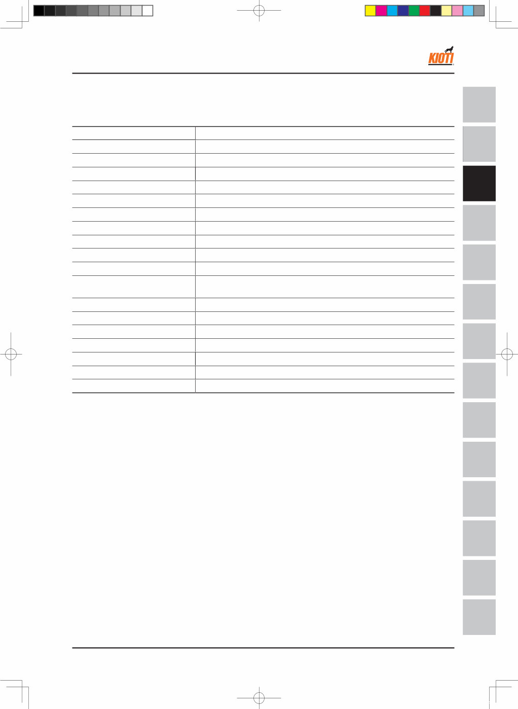
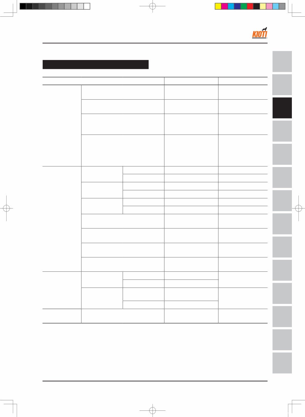
DH80-W00 Aug. 2011 3 -9 SAFETY FIRST GENERAL ENGINE CLUTCH TRANSMI SSION HST REAR AXLE BRAKE FRONT AXLE STEERING SYSTEM HYDRAULIC SYSTEM ELECTRIC SYSTEM CABIN A/C AND HEATER SAFETY FIRST GENERAL ENGINE CLUTCH TRANSMISSION REAR AXLE BRAKE FRONT AXLE STEERING SYSTEM HYDRAULIC SYSTEM ELECTRIC & CALIBRATION CABIN A/C & HEATER INDEX RX6010C(PC) ENGINE - SPECIFICATIONS Engine body Item Specification Allowable limit A. Cylinder Head Cylinder head surface flatness - 0.05 mm / 100 mm (0.002 in. / 3.94 in.) T.D.C clearance 0.750 ~ 0.9 mm (0.0294 ~ 0.0354 in.) - Gasket Thickness Tightened 1.21 mm (0.0476 in.) - Compression Pressure (When cranking with starter motor) Variance of compression pressure among cylinders should be 10% or less. 3.24 ~ 3.73 MPa 33 ~ 38 kgf/cm 2 469 ~ 540 psi 2.55 MPa 26 kgf/cm 2 370 psi B. Valves Valve Clearance (Cold) IN. 0.25 mm (0.010 in.) ± 0.05 mm (0.002 in.) EX. 0.3 mm (0.012 in.) ± 0.05 mm (0.002 in.) Valve Seat Angle IN. 60° (1.047 rad.) - EX. 45° (0.785 rad.) - Valve Face Angle IN. 60° (1.047 rad.) - EX. 45° (0.785 rad.) - Valve recess 0.2 ~ 0.5 mm (0.0079 ~ 0.0197 in.) 0.8 mm (0.0315 in.) Clearance Between Valve Stem and Valve Guide 0.040 ~ 0.070 mm (0.0016 ~ 0.0028 in.) 0.10 mm (0.039 in.) Valve Stem O.D. 7.960 ~ 7.975 mm (0.31339 ~ 0.31398 in.) - Valve Stem I.D. 8.015 ~ 8.030 mm (0.3156 ~ 0.3161 in.) - C. Valve Timing Intake Valve Open 0.14 rad (8°) before T.D.C - Close 0.611 rad (35°) after B.D.C Exhaust Valve Open 0.785 rad (45°) before B.D.C - Close 0.140 rad (8°) after T.D.C D. Cylinder Bore I.D. 87.000 ~ 87.022 mm (3.425 ~ 3.426 in.) 0.15 mm (0.0059 in.) 2.4 SERVICING SPECIFICATIONS 영M55(RX6010)_03장_엔진.indd 9 2011-11-01 오후 5:36:10
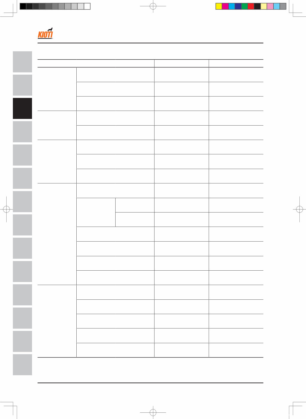
3 -10 DH80-W00 Aug. 2011 SAFETY FIRST GENERAL ENGINE CLUTCH TRANSMI SSION HST REAR AXLE BRAKE FRONT AXLE STEERING SYSTEM HYDRAULIC SYSTEM ELECTRIC SYSTEM CABIN A/C AND HEATER SAFETY FIRST GENERAL ENGINE CLUTCH TRANSMISSION REAR AXLE BRAKE FRONT AXLE STEERING SYSTEM HYDRAULIC SYSTEM ELECTRIC & CALIBRATION CABIN A/C & HEATER INDEX RX6010C(PC) Item Specification Allowable limit E. Valve spring Free length 41.7 ~ 42.2 mm (1.6417 ~ 1.6614 in.) 41.2 mm (1.6220 in.) Load after assembled / Length after assembled 12.0 kgf / 35.15 mm (26.5 lbs / 1.3839 in.) 10.2 kgf / 35.15 mm (22.5 lbs / 1.3839 in.) Squareness - 1.0 mm (0.039 in.) F. Rocker Arm Rocker arm shaft O.D. 18.955 ~ 18.980 mm (0.7463 ~ 0.7472 in.) - Rocker arm bushing I.D. 19.000 ~ 19.025 mm (0.7480 ~ 0.7490 in.) - G. Tappet Clearance between tappet and guide 0.020 ~ 0.062 mm (0.00079 ~ 0.00244 in.) 0.07 mm (0.0028 in.) Tappet O.D. 23.959 ~ 23.980 mm (0.94327 ~ 0.94410 in.) - Tappet guide I.D. 24.000 ~ 24.021 mm (0.94488 ~ 0.94571 in.) - H. Camshaft Camshaft deflection 0.01 mm (0.0004 in.) 0.05 mm (0.0020 in.) Cam height IN. 33.9 mm (1.335 in.) 33.54 mm (1.3205 in.) EX. 33.9 mm (1.335 in.) 33.64 mm (1.3244 in.) Journal oil clearance 0.050 ~ 0.091 mm (0.00197 ~ 0.00358 in.) 0.15 mm (0.0059 in.) Camshaft journal O.D. 39.934 ~ 39.950 mm (1.57220 ~ 1.57283 in.) 39.88 mm (1.5701 in.) Camshaft counter bore I.D. 40.000 ~ 40.025 mm (1.57480 ~ 1.57579 in.) - Clearance between camshaft gear (axial direction) 0.07 ~ 0.22 mm (0.003 ~ 0.009 in.) - I. Timing Gear Timing gear backlash 0.04 ~ 0.11 mm (0.0016 ~ 0.0043 in.) 0.15 mm (0.0059 in.) Idle gear axial clearance 0.20 ~ 0.51 mm (0.0079 ~ 0.0201 in.) 0.9 mm (0.035 in.) Clearance between Idle gear shaft and idle gear bushing 0.025 ~ 0.066 mm (0.00098 ~ 0.00250 in.) 0.1 mm (0.0039 in.) Idle gear shaft O.D. 37.9590 ~ 37.9750 mm (1.49445 ~ 1.49508 in.) - Idle gear bushing I.D. 38.000 ~ 38.025 mm (1.49608 ~ 1.49705 in.) - ENGINE - SPECIFICATIONS 영M55(RX6010)_03장_엔진.indd 10 2011-11-01 오후 5:36:10
Kioti Daedong RX6010C, RX6010PC Tractors OEM Service & Repair Manual
Models covered:
Kioti Daedong RX6010C
Kioti Daedong RX6010PC
The Kioti Daedong RX6010C, RX6010PC Tractors OEM Service & Repair Manual is the go-to reference for hands-on maintenance and in-depth mechanical work. Tailored specifically to the RX6010C and RX6010PC models, this manual covers factory procedures for every key system—engine, hydraulics, drivetrain, and more.
Whether you're sorting out a finicky front axle, servicing the hydraulic pump, or recalibrating controls in the cab, this guide lays it out clearly. You'll find full disassembly steps, torque specs, adjustment instructions, and inspection points—all presented in a no-nonsense, practical format. HVAC, steering alignment, transmission internals—it’s all here.
Content overview:
Safety and general information: service guidelines, specifications, and operator precautions
Engine service: inspection, disassembly, repair, and reassembly procedures
Clutch system: adjustments, servicing, and replacement instructions
Transmission: gear shifting mechanisms, troubleshooting, and repair procedures
Rear axle: disassembly, repair, and reinstallation of axle components
Brake system: hydraulic brake servicing, inspection, and adjustments
Front axle: maintenance, differential service, and component replacement
Steering system: steering gear, linkage, and alignment procedures
Hydraulic system: pump, valves, cylinders, and control system diagnostics and repair
Electrical and calibration: wiring diagrams, electrical components, and calibration procedures
Cabin service: controls, seating, panels, and operator comfort systems
Air conditioning and heating: HVAC system servicing, diagnostics, and repair
Index section: quick reference for all tractor service procedures
Great for both dealership techs and tractor owners who like getting their hands dirty, this manual helps you cut through guesswork and focus on the fix. It's written for real-world use, whether you're chasing a small issue or doing a full system overhaul. A solid tool to keep your Kioti running right.
Printable: Yes Language: English Compatibility: Pretty much any electronic device, incl. PC & Mac computers, Android and Apple smartphones & tablet, etc. Requirements: Adobe Reader (free)
Recently Viewed
5,521,897Happy Clients
2,594,462eManuals
1,120,453Trusted Sellers
15Years in Business
Price:
Actual Price:
Kioti Daedong RX6010C, RX6010PC Tractors OEM Service & Repair Manual