

Kioti Daedong DK Series DK65 DK75 DK80 DK90 Tractor Service & Repair Manual
What's Included?
Fast Download Speeds
Offline Viewing
Access Contents & Bookmarks
Full Search Facility
Print one or all pages of your manual


CHAPTER 1
GENERAL INFORMATION

- 3-
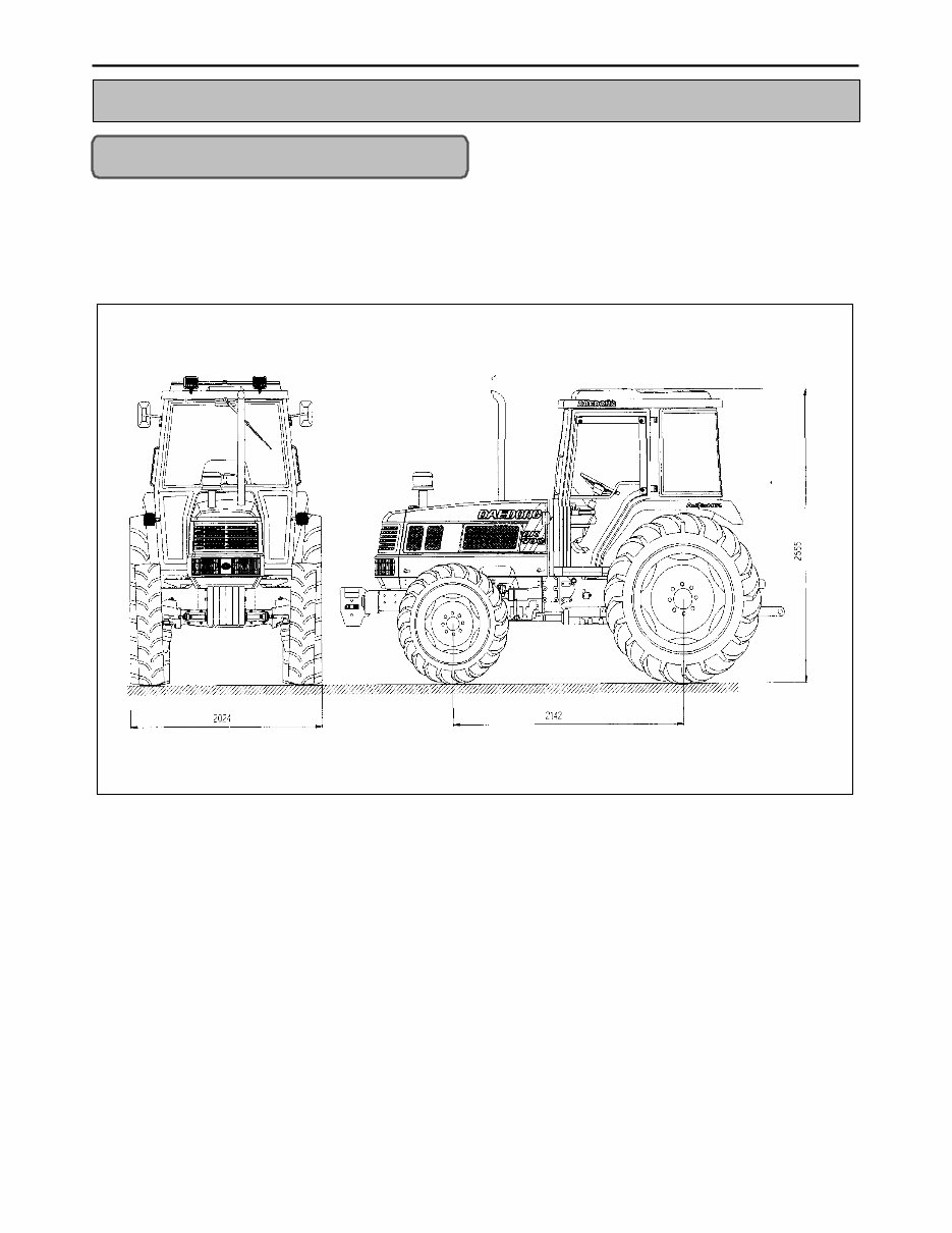
1-1. Outside diagram
1. General information

- 4-
1-2. Specifications
Model DK 75 DK 80 DK 90
Type 4-cylinder engine ← ←
Name 1004.4 1004.42 1004.4T
Total displacement 3989 cc 4233 3989
Cylinder inner diameter x stroke
100 x 127 (mm),3.94 x
5(in)
103 x 127 (mm),4.06
x 5(5in)
100 x 127 (mm),3.94
x 5(in)
Gross power (Horsepower/rpm) 75ps / 2200rpm 80ps / 2300rpm 90ps / 2200rpm
Battery capacity 12V65AHX2 ← ←
Fuel consumption Diesel ← ←
Engine
Fuel tank capacity 100l,105.6u.s.qts ← ←
Starting method Electric start ← ←
Overall length 4320 mm, 170in ← ←
Overall width 2024 mm, 79.7in ← ←
Height 2655 mm, 104.5in ← ←
Length of shaft 2142 mm, 84.3in ← ←
Front wheel 1513 mm, 59.6in ← ←
Wheel track
Rear Wheel 1534 mm,60.4in ← ←
Vehicle size
Ground clearance 496 mm, 19.5in ← ←
Weight 3055 kg, 6735 lbs 3050 kg, 6724 lbs 3080 kg, 6790 lbs
Drive system 4-Wheel drive ← ←
Front wheel 12.4-24 ← ←
Tire size
Rear wheel 18.4-34 ← ←
Clutch Dry, single disc ← ←
Steering type Hydraulic ← ←
Brake Hydraulic, wet disc ← ←
Differential lock Spiral bevel gear ← ←
Traveling dimensions
Transmission 12F/12R ← ←
Minimum turning radius (using side brake) 3325 mm,130.9in ← ←
Hydraulic control
Position, draft, mixed
control
← ←
Hydraulics
Pump capacity
First(lifting):46l/min, 48.6u.s.qts/ min.
Second(steering wheel):32l/min, 33.8u.s.qts/ min.
3-Point link Category ← ←
Rotation direction Right ← ←
Transmission gear stage Second gear ← ←
Speed (rpm)
1st 540/2200
2nd 717/2200
1st 563/2300
2nd 750/2300
1st 540/2200
2nd 717/2200
P.T.O shaft
Shaft dimensions 35mm(1.38in) x 6
spline (JIS35)
← ←
The above dimensions can be changed for the improvement of the product without any notice.
- 5-
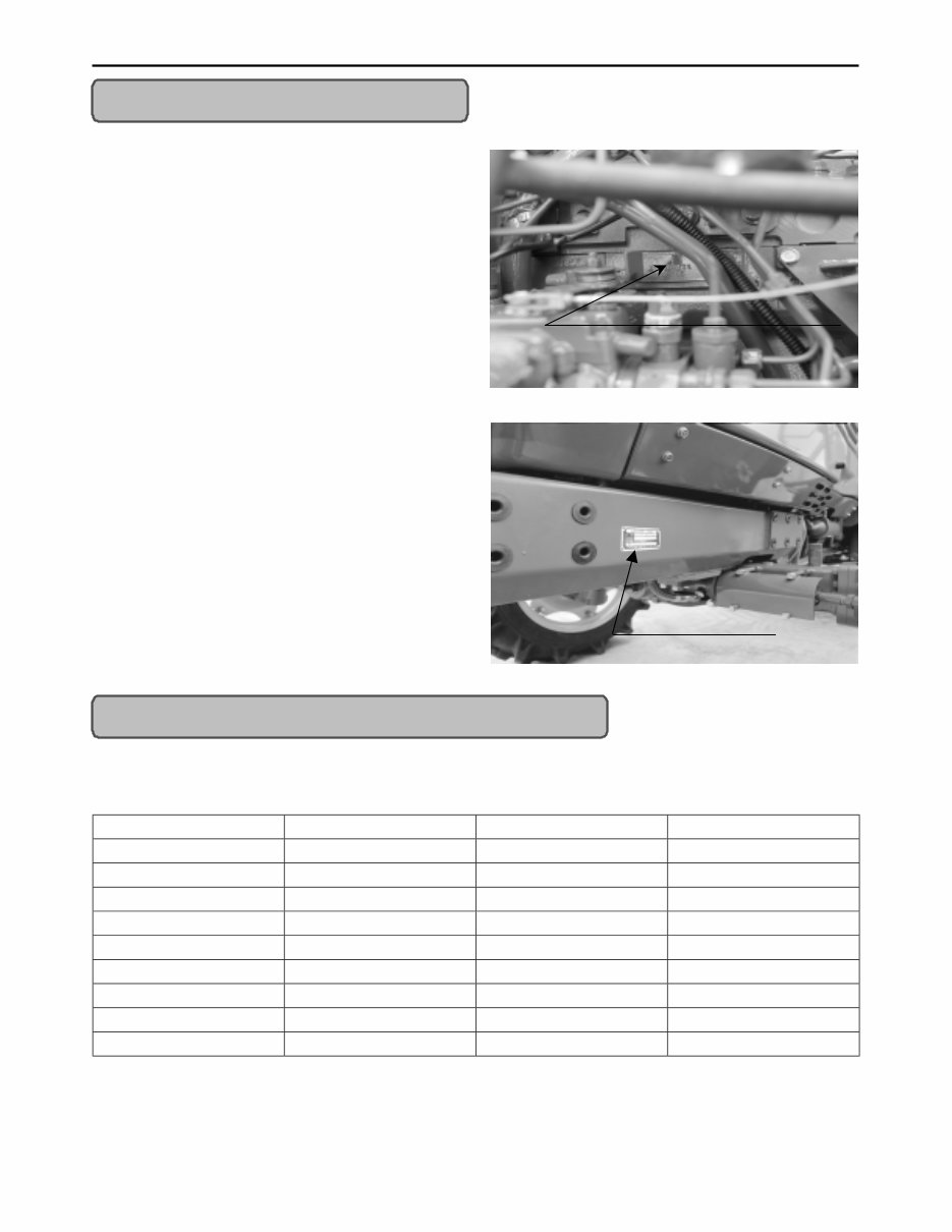
1-3. Identification
1) Engine number
Engine number is carved in the left side of the cylinder
block as shown in the figure.
Engine number fills the important role of providing its
record.
2) Chassis number of the tractor
(Chassis number of the machine)
Chassis number of the tractor is carved in the left side
of the front axle frame as shown in the figure.
1-4. Tightening torque for standard bolts and nuts
1) Tightening torque
1. Tightening torque for standard bolts and nuts
Grade 4T (Standard bolt) 7T 9T
Name SS41, S20C S43C, S48C SCR3, SCM3
M6 0.80~0.95 1.10~1.15 1.25~1.45
M8 1.80~2.10 2.40~2.80 3.00~3.50
M10 4.00~4.60 4.90~5.70 6.20~7.20
M12 6.40~7.40 7.90~9.20 10.5~12.0
M14 10.0~12.8 12.6~15.0 17.0~20.0
M16 17.0~19.5 20.0~23.0 26.5~31.0
M18 25.0~29.0 28.0~32.5 35.0~41.0
M20 34.0~40.0 37.5~44.0 50.0~58.0
Engine serial number
Identification Plate
- 6-
2. Tightening torque for studs
M8 : 1.2 ~ 1.6 kgf.m
M10 : 2.5 ~ 3.2 kgf.m
M12 : 3.5 ~ 5.0 kgf.m
3. Tightening torque for high pressurized hose union nuts
Hose size (I.D inch) 1/8” 3/16” 1/4” 5/16” 3/8” 1/2” 5/8”,3/4” 1”
Screw size (PF) 1/8” 1/4” 1/4” 3/8” 3/8” 1/2” 3/4” 1”
Tightening torque (kgm) 1 2.5 2.5 5 5 6 12 14
1-5. Caution before repair
1) Before repair or inspection
1. In case of repair or inspection, locate the tractor on the flat ground and pull the parking brake on.
2. Except for the items to be checked while the engine is running, be sure to stop the engine prior to the work.
3. When washing parts, apply parts detergent on sale for industrial use (avoid using gasoline so to prevent
environmental pollution). For the hydraulic parts, apply designated functioning oil in washing.
4. When disassembling and assembling of the hydraulic apparatus, pay special attention not to allow dust or
foreign substance to be attached or intermixed.
2) Assembly and disassembly
To check an error, try to find out its underlying cause. If assembly or disassembly is needed, perform the work
in regular sequence as specified in this repair manual.
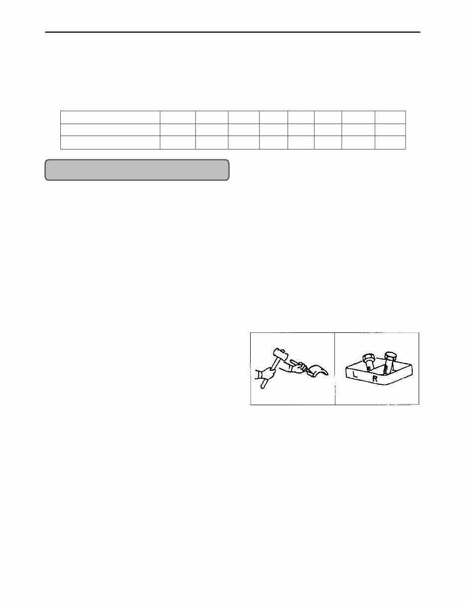
1. Disassembled parts shall be arranged orderly.
2. Sort out the parts to be replaced from the ones to be
recycled.
3. Be sure to use standard bolts and nuts designated.
4. When assembling snap rings or spring pin types, take
care of assembling direction.
5. Split pin shall be spread surely not to escape when installed.
6. When using sealant (such as gasket bond) on the assembled surfaces, apply it evenly and incressantly in a
height of 3-5mm on the contact surface after removing the old bond and cleaning the sealing surface with
gasolinic wax. Apply sealant on the center of the contact surface for the space between the bolt holes of the
contact surface, and on the more inner side than the bolt hole for the bolt area.
7. Finish assembly within 20 minutes after applying sealant, after that, wait approx. 30 minutes later before
filling with oil.
- 7-
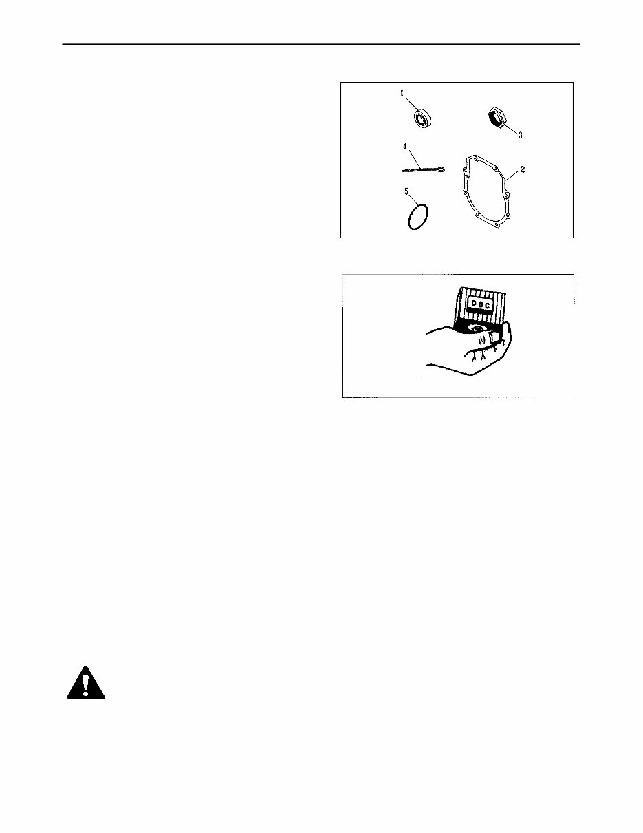
3) Parts to be replaced
The following parts shall be replaced with new one if
once removed.
Oil seal
Gasket
Lock nut
split pin
O-ring
4) Parts
When replacing parts, use only the genuine.
5) Asbestos parts
Since dust out of asbestos fibrous parts is extremely injurious to health, be sure to clean such parts by air-
tightened and thoroughly sealed up vacuum cleaner while not using compressed air.
6) Electrical system
1. Check electrical wiring daily every year for any damage or short circuit at junction. In addition, undergo
onerous inspection via the agency regularly.
2. Do not modify or reorganize the wiring of the electric field parts.
3. When disconnecting battery cable disconnect negative cable first, reinstall the positive cable first when
reinstalling
Disconnect battery negative terminal
Be sure to turn the starting key OFF when
connecting or disconnecting the cable
Note
- 8-
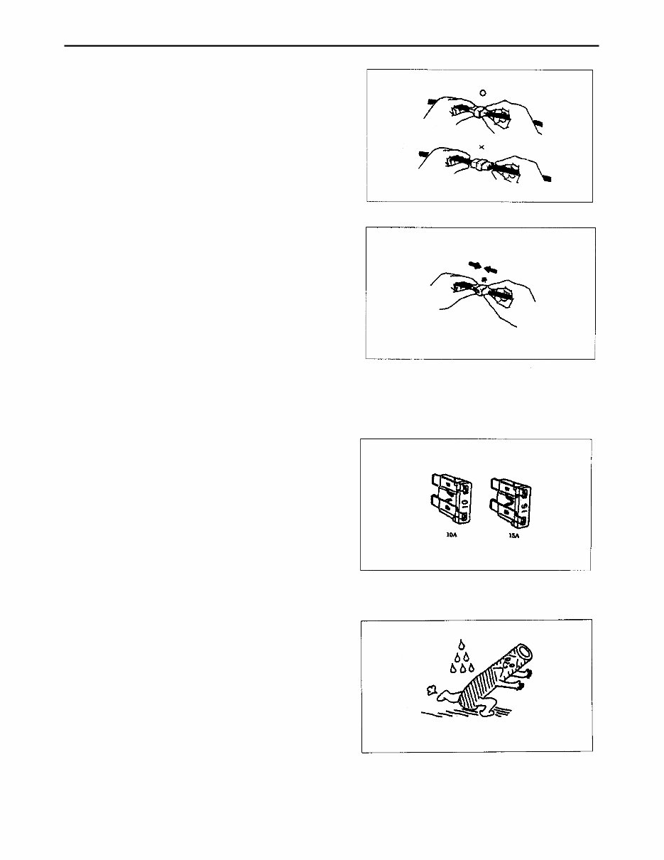
4. Remove the connector by pulling the plastic section
not the wiring.
5. When connection the connector, insert it until it snaps.
6. Be sure not to drop sensors and relays which are fragile.
7. When replacing a broken fuse with a new one, be sure
to use the fuse of capacity as specified.
7) Tubes and rubbers
Be cautious of oil or the like on the tubes and rubber
parts, which may cause change in quality.

- 9-
8) Lubricant
When assembling and fixing, apply designated lubricant
where specified in accordance with this repair manual.
You're Reading a Preview
What's Included?
Fast Download Speeds
Offline Viewing
Access Contents & Bookmarks
Full Search Facility
Print one or all pages of your manual
$39.99
Viewed 25 Times Today


Secure transaction
What's Included?
Fast Download Speeds
Offline Viewing
Access Contents & Bookmarks
Full Search Facility
Print one or all pages of your manual
$39.99
The Kioti Daedong DK Series DK65 DK75 DK80 DK90 Tractor Service & Repair Manual is a comprehensive factory manual designed for servicing and repairing Kioti Daedong DK series tractors. This professional manual is suitable for both professional mechanics and DIY enthusiasts. It provides detailed instructions, troubleshooting procedures, and hundreds of pages with photos and diagrams to assist in completing every job correctly.
Key features of this manual:
- Complete factory service repair workshop manual
- No extra fees or expiry dates
- Accessible for instant download to your computer, tablet, or smartphone
- Allows printing of single pages or the entire manual
- Can be used on multiple computers without limitations
- Compatible with both Windows and MAC computers
- Full version without any trial periods or renewal fees
For more information and to access this valuable manual, please click on the provided button.


