4.1 SEPARATING THE HYDRAULIC PUMP ........................................................................................... 8-12 4.2 SEPARATING THE STEERING UNIT ............................................................................................... 8-14 4.3 DISASSEMBLING OF THE STEERING CYLINDER ....................................................................... 8-23 4.4 SERVICING .......................................................................................................................................... 8-24 CHAPTER 9 HYDRAULIC SYSTEM ............................................................................................... 9-1 1. STRUCTURE ................................................................................................................................................... 9-3 1.1 HYDRAULIC OIL FLOW SHEMATIC ................................................................................................... 9-3 1.2 HYDRAULIC CIRCUIT SHEMATIC ..................................................................................................... 9-4 1.3 HYDRAULIC FILTER SHEMATIC ........................................................................................................ 9-5 1.4 HYDRAULICPUMP SHEMATIC ........................................................................................................... 9-5 1.5 POWER STEERING SYSTEM ............................................................................................................. 9-6 1.6 PTO CLUTCH VALVE SYSTEM ........................................................................................................... 9-8 1.7 4WD,Q/T AND Q/T (AB) SYSTEM ........................................................................................................ 9-9 1.8 JOYSTICK VALVE ................................................................................................................................ 9-10 1.9 HORIZONTAL CONTROL SYSTEM (ONLY JP) .............................................................................. 9-11 1.10 HYDRAULIC POWER LIFT SYSTEM ................................................................................................ 9-12 1.11 AUXILIARY CONTROL VALVE (IF EQUIPPED) ............................................................................... 9-13 2. TROUBLINGSHOOTING ............................................................................................................................... 9-14 2.1 JOYSTICK VALVE ................................................................................................................................ 9-14 2.2 HYDRAULIC LIFT SYSTEM ............................................................................................................... 9-15 3. CHECKING,DISASSEMBLING AND MAINTENANCE ............................................................................... 9-16 3.1 HYDRAULIC FILTER .......................................................................................................................... 9-16 3.2 HYDRAULIC PUMP ............................................................................................................................. 9-16 3.3 POWER STEERING UNIT .................................................................................................................. 9-18 3.4 PTO CLUTCH VALVE .......................................................................................................................... 9-19 3.5 4WA,Q/T AND Q/T(AB) VALVE ............................................................................................................ 9-23 3.6 JOYSTICK VALV ................................................................................................................................... 9-27 3.7 HORIZONTAL CONTROL VALVE ...................................................................................................... 9-28 3.8 HYDRAULIC LIFT SYSTEM ............................................................................................................... 9-30 CHAPTER 10 CABIN SYSTEM ...................................................................................................... 10-1 1. STRUCTURE ................................................................................................................................................. 10-3 1.1 HEATER ................................................................................................................................................ 10-3 1.2 AIR-CONDITIONER ............................................................................................................................ 10-4 2. TROUBLESHOOTING ................................................................................................................................... 10-6 3. INSPECTION AND ADJUSTMENTS ......................................................................................................... 10-14
CHAPTER11 ELECTRIC SYSTEM .................................................................................................. 11-1 1. HOW TO WIRING DIAGRAM ........................................................................................................................ 11-3 1.1 WIRE CODE ......................................................................................................................................... 11-3 1.2 WIRE SIZEW ........................................................................................................................................ 11-3 1.3 INSTRUMENT PANEL BULBS .......................................................................................................... 11-4 1.4 RELAY AND SWITCH .......................................................................................................................... 11-5 1.5 MULTIPLE SWITCH ............................................................................................................................ 11-5 1.6 RELAY BOX .......................................................................................................................................... 11-6 1.7 FUSE CHECK ...................................................................................................................................... 11-7 1.8 WIRING DIAGRAM .............................................................................................................................. 11-9 2. INSTRMENT PANEL .................................................................................................................................... 11-11 2.1 SYMBOL DESCRIPTION .................................................................................................................. 11-11 2.2 CIRCUIT DIAGRAM OF INSTRUMENT(USA) ............................................................................... 11-14 3. STSRTING SYSTEM .................................................................................................................................... 11-15 3.1 IGNITION CIRCUIT(WITHOUT THE INSTALLATION OF HORIZONTAL CONTROLLER ....... 11-15 3.2 IGNITION CIRCUIT(HORIZONTAL CONTROL INSTALLATION EXPECTATION ONLY JP ..... 11-16 3.3 MAJOR COMPONENTS ................................................................................................................... 11-17 4. CHARGING SYSTEM ................................................................................................................................... 11-22 4.1 CIRCUIT DIAGRAM ........................................................................................................................... 11-22 4.2 AC (ALTERNATING CURRENT)ALTERNATOR ............................................................................ 11-23 5. ENGINE GLOW PLUG SYSTEM ................................................................................................................ 11-25 5.1 CIRCUIT DIAGRAM ........................................................................................................................... 11-25 5.2 MAJOR COMPONENTS ................................................................................................................... 11-26 6. PTO SYSTEM(ONLY USA) .......................................................................................................................... 11-29 6.1 CIRCUIT DIAGRAM ........................................................................................................................... 11-29 6.2 CIRCUIT DESCRIPTION ................................................................................................................. 11-30 6.3 TROUBLESHOOTING ...................................................................................................................... 11-30 7. ROTARY LEVEL CONTROL INSTALLATION(ONLY JP) ......................................................................... 11-31 7.1 SYSTEM COMPOSITION PARTS .................................................................................................... 11-31 7.2 OUTLINE ............................................................................................................................................ 11-32 7.3 LEVEL CONTROL INSTALLATION FUCTION ............................................................................... 11-34 7.4 ELECTRIC CIRCUIT ........................................................................................................................ 11-36 7.5 TERMINAL ARRANGEMENT TABLE ............................................................................................... 11-37 8. QUECK TURN(ONLY JP) ........................................................................................................................... 11-38 8.1 ELECTRIC CIRCUIT ........................................................................................................................ 11-38 8.2 MAIN PARTS COMPOSITION .......................................................................................................... 11-40 8.3 REPAIRS FOR QUECK TURN1 MALFUCTION ............................................................................ 11-42 9. AIR CONDITIONING SYTEM ...................................................................................................................... 11-43 9.1 CIRCUIT DIAGRAM ........................................................................................................................... 11-43 9.2 MAJPR COMPONENTS .................................................................................................................... 11-44 10.HEATER SYSTEM ........................................................................................................................................ 11-46
TO THE READER 1 A13-WOO Dec. 2004 TO THE READER This Workshop Manual has been prepared to provide servicing personnel with information on the mechanism, service and maintenance of KIOTI (DAEDONG) tractors DK50S/55(DK501/551). It is divided into two parts, “Mecha- nism” and “Servicing”. MECHANISM Information on the construction and functions are included. The part should be completely understood before proceeding with troubleshooting, disassembling or servicing. SERVICING In this section you will find general precautions, maintenance and special tools. The are other sections which include troubleshooting, servicing, specifications lists, disassembling, assembling and servicing that explains in detail procedures, precautions, factory specifications and acceptable limits. This manual contains the latest production information on illustrations and specifications based on the most up to date production information available at the time of publication. We reserve the right to make changes throughout the entire manual at any time without notice.
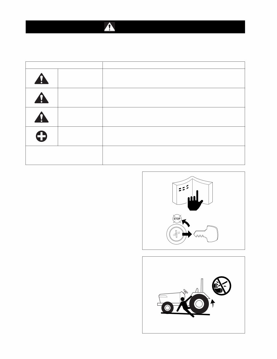
DK50S/55(DK501/551) 2 A13-WOO Dec. 2004 SAFETY STARTING 1. Always use the safety start switch to start the en- gine and never by any other means. 2. Do not alter or remove any part of machine safety system. 3. Before starting the engine, make sure that all shift levers are in neutral positions or in the disengaged positions. 4. Never start the engine unless you are in the operator’s seat. A13W002A This symbol, the industry’s “Safety Alert Symbol”, is used throughout this manual and the decals on the machine itself to warn of the possibility of personal injury. It is essential that you read the instructions and safety regulations before you attempt to repair or operate this unit. Read these instructions carefully. SAFETY FIRST SIGNS DANGER WARNING CAUTION IMPORTANT DESCRIPTION This mark indicates hazardous situation which, if not observed, may result in death or fatal injury. This mark should be indicated for most dangerous situations only. This mark indicates potentially hazardous situation which, if not observed, may result in death or moderate injury. This mark indicates potentially hazardous situation which, if not observed, may result in minor or moderate injury. And this mark can be used as a warning against unsafe activities. This mark indicates emphasis on notable characteristics in working procedures or information on working procedures and technology for convenient use. NOTE Gives helpful information. BEFORE SERVICING AND REPAIRING 1. Read all safety instructions in this manual and be aware of the safety decals on your machine itself. 2. Thoroughly clean your work area and the machine. 3. Make sure the machine is on firm and level ground and that the parking brake is set. 4. Lower the implement to the ground. 5. Stop the engine and remove the key. 6. Disconnect the negative battery cable. 7. Place a “DO NOT OPERATE” tag in operator station. A13W001A
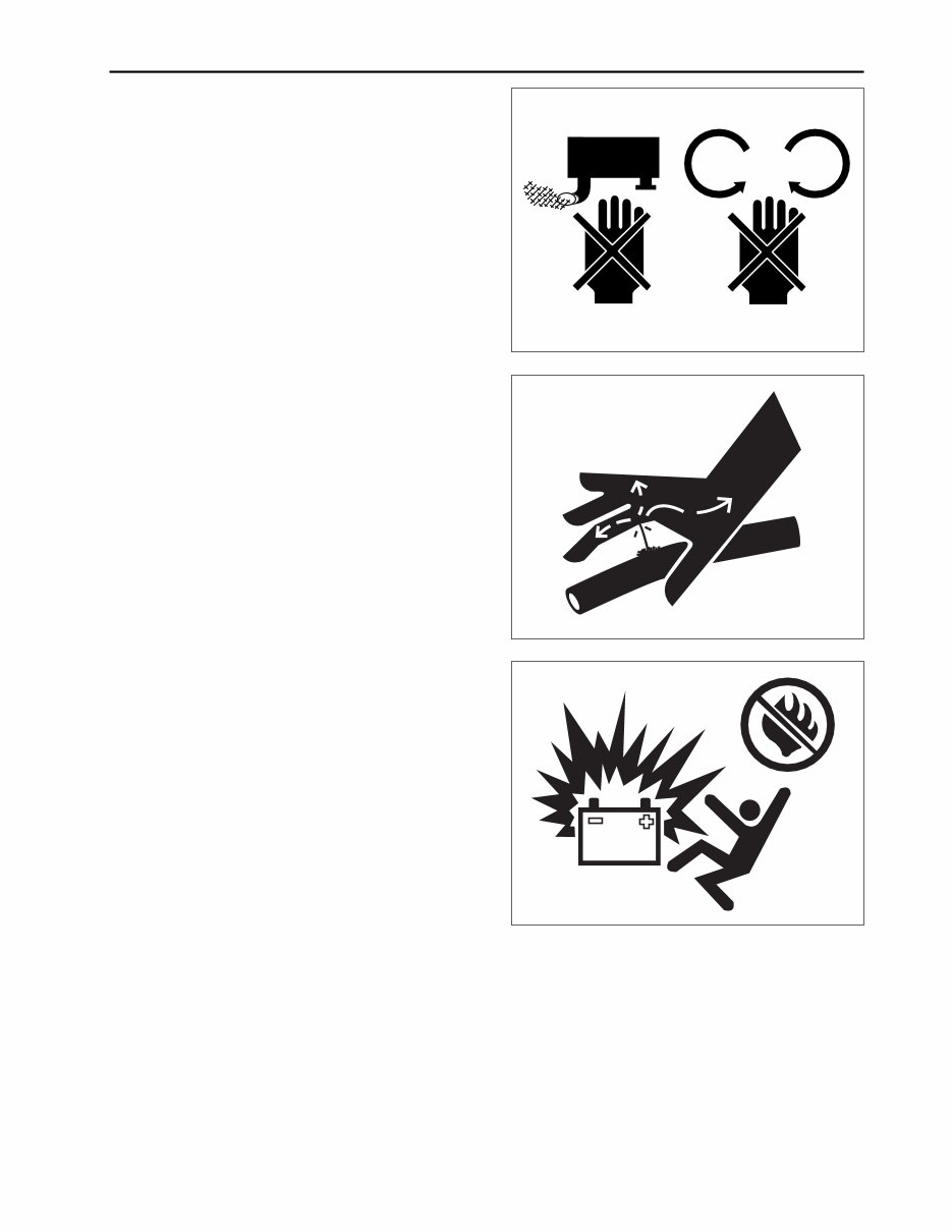
TO THE READER 3 A13-WOO Dec. 2004 SAFETY WORKING 1. Do not operate or service the machine while under the influence of alcohol, medication, or other substances. 2. Never wear loose fitting clothing and always use safety equipment appropriate to the job. 3. Never use improvised tools, parts or procedures. Use only recommended tools appropriate to the work. 4. Be careful to perform all work safely when servicing is done by two or more people. 5. Always support the machine by safety stands. Never work under the machine that is supported solely by a jack. 6. Do not touch any rotating or hot parts while the en- gine is running. 7. Never remove the radiator cap while the engine is running, or immediately after stopping. Only remove radiator cap when it is cool enough to touch with bare hands. Slowly loosen the cap to relieve pres- sure before removing completely. 8. Escaping fluid (fuel or hydraulic oil) under pressure can penetrate the skin causing serious injury. Relieve pressure before disconnecting hydraulic or fuel lines. Tighten all connections before applying pressure. A13W003A A13W004A AVOID FIRES 1. Never smoke or allow flames or sparks in your work area, as fuel is extremely flammable and explosive under certain conditions. 2. Always disconnect the negative battery cable first and reconnect it last to avoid sparks from an acci- dental short circuit. 3. Battery gas will ignite. Keep sparks and open flame away from the top of battery, especially while charging. 4. Be careful not to spill fuel on the engine. A13W005A
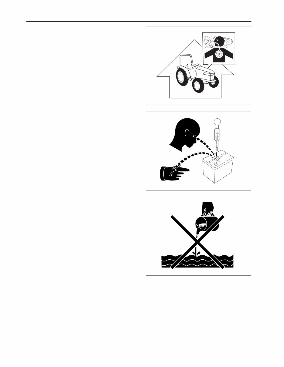
DK50S/55(DK501/551) 4 A13-WOO Dec. 2004 DISPOSE OF FLUIDS PROPERLY 1. Observe relevant environmental protection regula- tions when disposing of oil, fuel, coolant, electro- lyte and other harmful waste. Never pour fluids into the ground, down a drain, or into a stream, pond, or lake. A13W008A VENTILATE WORK AREA 1. Exhaust contains poisonous carbon monoxide, so you should never run the engine in a closed area. If the engine must be running while performing maintenance, make sure the area is well ventilated. PREVENT ACID BURNS 1. Sulfuric acid in battery electrolyte is poisonous. It is strong enough to burn skin, clothing and cause blindness if splashed into eyes. Keep electrolyte away from eyes, hands and clothing. If you spill elec- trolyte on yourself, flush with water, and get medi- cal attention immediately. A13W006A A13W007A
This workshop service and repair manual provides in-depth and highly detailed instructions for working on Kioti Daedong DK50S, DK55, DK501, and DK551 tractors. It is designed to help both professional mechanics and DIY enthusiasts save on repair costs and maintain their vehicles in pristine condition. The manual includes step-by-step instructions and detailed exploded pictures for efficient completion of various tasks.
Model Covered:
Kioti Daedong DK50S
Kioti Daedong DK55
Kioti Daedong DK501
Kioti Daedong DK551
Service Manual Covers:
General Information
Engine
Transmission
Clutch
Cooling System
Fuel System
Front Axle
Rear Axle
Braking System
Hydraulic System
Electrical System
Main Body
Steering System
Wiring Diagrams
Maintenance
Technical Information & Specifications
This manual is designed for viewing on Windows PC, Mac, tablet, smartphone, etc., and can be printed for easy access during vehicle maintenance. It is the only workshop service manual you will ever need, providing instant access without any shipping costs or waiting time. The manual also offers the option to print the entire document for a hardcopy.
If you are unable to find a specific manual, you can search the shop or contact the customer support team for assistance in locating it.
Thank you for visiting our page and have a nice day!