

Kioti Daedong DK35/DK40 Tractors OEM Service & Repair Manual
What's Included?
Fast Download Speeds
Offline Viewing
Access Contents & Bookmarks
Full Search Facility
Print one or all pages of your manual
BRAKE
3-97
MODEL: DK450L
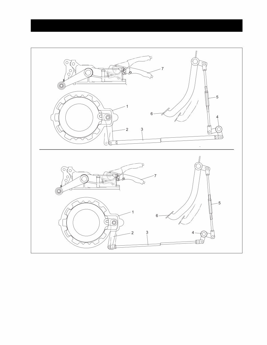
• For the left and right running brake, an independent
mechanical wet disc brake is used and operated
through brake pedal by mechanical linkage.
• It enables the parking brake when parking. If brake
pedal is locked with the parking brake lever pulled
up, it keeps the brakes locked.
(1) Brake Case
(2) Brake Cam Lever
(3) Brake Rod
(4) Brake Lever
(5) Turn Buckle
5. BRAKE
5.1 STRUCTURE
(6) Brake Pedal
(7) Parking Brake Lever
• Brake disc of wet disc type soaked in oil has more
durability and braking force than an inside expand-
able dry brake type.
MODEL: DK35, DK40
643W601A
BRAKE
3-98
643W603A
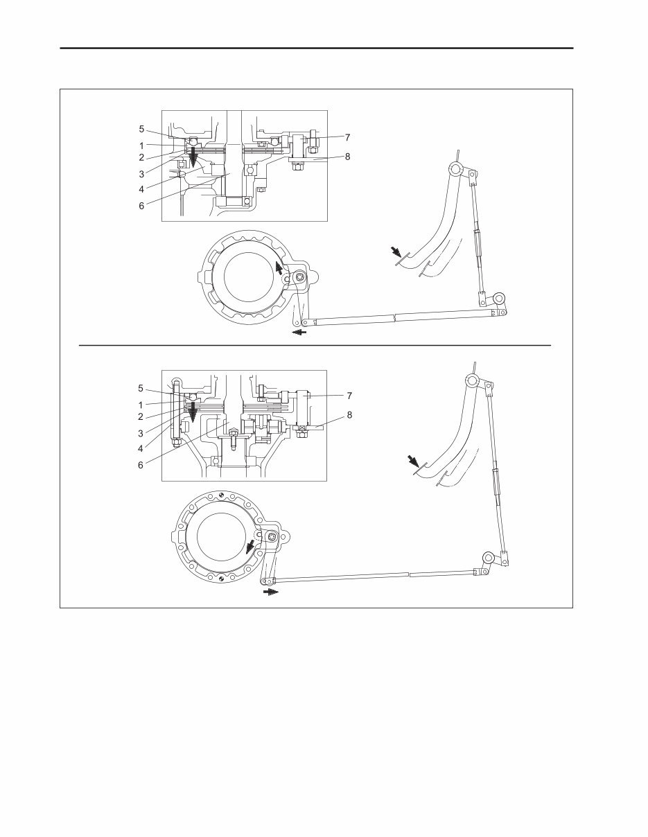
5.2 OPERATION
(1) Cam Plate (3) Brake Plate
(2) Brake Disc (4) Brake Case
(5) Ball (7) Brake Cam
(6) Gear Shaft (8) Brake Cam Lever
MODEL: DK35, DK40
MODEL: DK450L
Operational Principle
If depressing brake pedal, brake cam lever (8) will be moved in the arrow direction by linkage as shown in the
above figure. The cam plate (1) is rotated in the direction of the arrow and raised above ball (5) and brake disc (2)
when it is applied with pressure. As brake disc is pressurized by the cam plate it grips the gear shaft (6) by friction
force of the disc, then the brakes will be applied.
BRAKE
3-99
5.4 MAINTENANCE SPECIFICATION
-
-
-
0.3 mm
(0.012 in.)
0.3 mm
(0.012 in.)
20.5 mm
(0.8071 in.)
4.2 mm
(0.165 in.)
2.10 mm
(0.0433 in.)
25 ~ 35 mm
(0.98 ~ 1.38 in.)
5 mm
(0.197 in.)
0 ~ 1 mm
(1 ~ 0.039 in.)
0.085 ~ 0.327 mm
(0.00335 ~ 0.01287 in.)
20.060 ~ 20.281 mm
(0.78976 ~ 0.79846 in.)
19.957 ~ 19.975 mm
(0.78559 ~ 0.78642 in.)
0.3 mm
(0.012 in.)
20.9 ~ 21.1 mm
(0.8228 ~ 0.8307 in.)
4.6 ~ 4.8 mm
(0.181 ~ 0.189 in.)
2.54 ~ 2.66 mm
(0.1000 ~ 0.1047 in.)
Clearance
Deviation
Clearance
Clearance
I.D
O.D
Flatness
Height
Thickness
Thickness
Brake pedal
Difference between left and right
when not depressing brake pedal
Brake pedal and stop switch
Between brake lever bush and
brake shaft
Brake lever bush
Brake shaft
Cam plate
Cam plate and ball
Brake disc
Plate
Item Reference Value Allowable Limit
5.5 TIGHTENING TORQUE
36.2 ~ 43.4
17.4 ~ 20.2
Stud.
Lever shaft, bolt
Item lbf·ft
5.0 ~ 6.0
2.4 ~ 2.8
Kgf·m
49.0 ~ 58.8
23.6 ~ 27.4
N·m Spec
M18
M8
Adjust
Replace
Replace
Adjust
Replace
Replace
Replace
Adjust
Replace
Replace
Replace
Change
• Brake pedal clearance is not constant
• Brake disc is worn
• Cam clutch is bent
• Brake pedal clearance is too small
• Cam plate ball is worn unequally
• Brake pedal return spring is worn or
broken
• Brake cam is corroded (rust)
• Brake pedal clearance is excessive
• Brake disc is worn
• Cam plate is bent
• Brake cam or lever is worn
• Transmission oil is improper
Brake power is not
constant
Brake is trailed
Brake power is weaken
Trouble Probable Cause Remark Remedy
5.3 TROUBLESHOOTING
-
-
-
BRAKE
3-100
643W605A
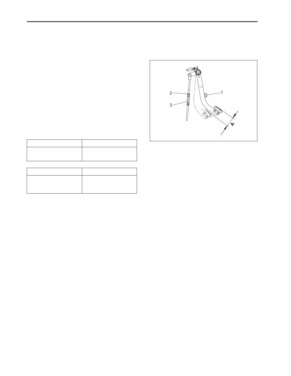
A. DISASSEMBLY, MAINTENANCE
[CHECK AND ADJUSTMENT]
a. First Stage (Clearance Adjustment of Brake
Pedal)
1. Disengage the brake pedal connection hook (1) and
measure the clearance of left and right pedals.
2. If the clearance of left and right pedals exceeds the
specified limit, loosen lock nut (2) and adjust clear-
ance using a turn buckle (3).
3. If setting clearance of pedal, tighten firmly with lock
nut.
IMPORTANT:
• Clearance of pedal should be equal in left and right.
Sect. Specified
Clearance of brake pedal
(A)
25 ~ 35 mm
0.98 ~ 1.38 in.
Sect. Specified
Gap between left and
right when depressing
brake pedal
Within 5 mm
Within 0.197 in.
(1) Connection Hook (3) Turn Buckle
(2) Lock Nut
5.6 BRAKE PEDAL
BRAKE
3-101
643W606A
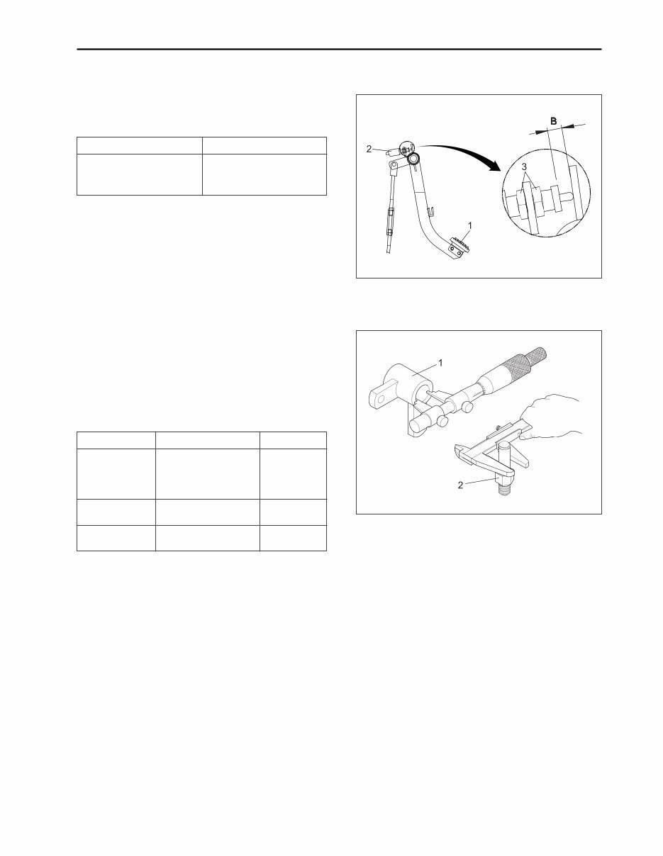
1. Check the clearance between brake pedal (1) and
stop switch (2) and if it exceeds the specified limit,
loosen the lock nut (3) and readjust.
Sect. Specified
Clearance between
brake pedal and stop
switch (B)
0 ~ 1 mm
0 ~ 0.039 in.
(1) Brake Pedal (3) Lock Nut
(2) Stop Switch
B. MAINTENANCE
Check the clearance between brake lever bush and
brake shaft
1. Measure I.D. of brake lever bush.
2. Measure O.D. of brake shaft.
3. Calculate the clearance with the measured value. If
exceeding the allowable limit, replace bush.
Sect. Specified Allowable Limit
Clearance
between brake
lever bush and
brake shaft
I.D. of brake
lever bush
O.D. of brake
shaft
0.085 ~ 0.327 mm
(0.00335 ~ 0.01287 in.)
20.060 ~ 20.281 mm
(0.78976 ~ 0.79846 in.)
19.954 ~ 19.975 mm
(0.78559 ~ 0.78642 in.)
b. Second Stage (Gap Adjustment of Stop
Switch)
643W607A
(1) Brake Lever Bush (2) Brake Shaft
-
-
-
You're Reading a Preview
What's Included?
Fast Download Speeds
Offline Viewing
Access Contents & Bookmarks
Full Search Facility
Print one or all pages of your manual
$46.99
Viewed 25 Times Today


Secure transaction
What's Included?
Fast Download Speeds
Offline Viewing
Access Contents & Bookmarks
Full Search Facility
Print one or all pages of your manual
$46.99
- The Kioti Daedong DK35/DK40 Tractors Service & Repair Manual is a comprehensive technical guide designed to assist with the maintenance and repair of these tractor models.
- It provides detailed instructions and precise specifications for accurate maintenance and effective troubleshooting.
- The manual includes step-by-step procedures for routine maintenance tasks such as oil changes, filter replacements, and hydraulic system checks.
- It also covers more complex repairs, including engine diagnostics, transmission servicing, and electrical system troubleshooting.
- Detailed diagrams and illustrations aid in the identification and repair of components, ensuring each task is performed correctly and efficiently.
- It is ideal for professional technicians and experienced DIY enthusiasts, delivering essential technical information to keep your Kioti Daedong DK35/DK40 tractors running smoothly.
- Following the detailed guidance provided can ensure long-term reliability and optimal performance, maximizing the operational lifespan of your tractors.
- Printable: Yes
- Language: English
- Compatibility: Pretty much any electronic device, including PC & Mac computers, Android and Apple smartphones & tablets, etc.
- Requirements: Adobe Reader (free)


