

John Deere 760 Tractor Service Manual
What's Included?
Fast Download Speeds
Online & Offline Access
Access PDF Contents & Bookmarks
Full Search Facility
Print one or all pages of your manual
SERVICE MANUAL
John Deere Dubuque Works
SM-2075 (Jun-67)

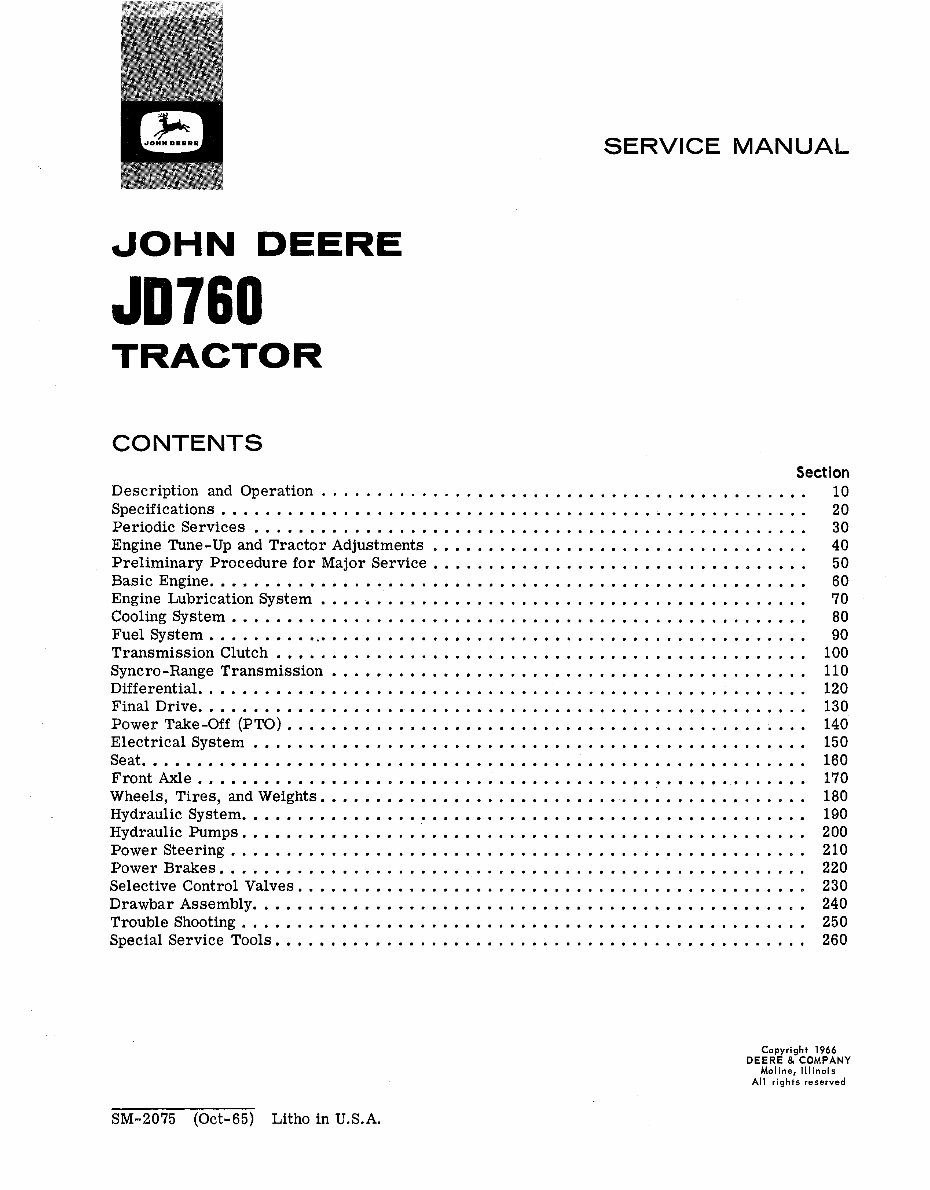
SERVICE MANUAL
JOHN DEERE
JD760
TRACTOR
CONTENTS
Section
Description and Operation ............................................
10
Specifications .....................................................
20
Periodic Services ..................................................
30
Engine Tune-Up and Tractor Adjustments .................................. 40
Preliminary Procedure for Major Service .................................. 50
Basic Engine. .....................................................
60
Engine Lubrication System ............................................
70
Cooling System ....................................................
80
Fuel System. ......................................................
90
Transmission Clutch ................................................
100
Syncro-Range Transmission ........................................... 110
Differential. ......................................................
120
Final Drive. ......................................................
130
Power Take-Off (PTO) ............................................... 140
Electrical System .................................................. 150
Seat ............................................................
160
Front Axle .......................................................
170
Wheels, Tires, and Weights. ............................................ 180
Hydraulic System. ..................................................
190
Hydraulic Pumps. .................................................. 200
Power Steering, ................................................... 210
Power Brakes. .................................................... 220
Selective Control Valves, ............................................. 230
Drawbar Assembly. ................................................. 240
Trouble Shooting, .................................................. 250
Special Service Tools. ............................................... 260
Copyright 1966
DEERE&COMPANY
Moline, Illinois
All rights reserved
SM-2075 (Ott-65) Litho in U.S.A.
2
Tractor, JD760-
Introduction
TO THE JOHN DEERE SERVICEMAN
This service manual contains maintenance in-
structions for John Deere JO760 Tractors. In-
cluded are complete instructions for removal,
disassembly, inspection, repair, assembly and
installation of the major parts and assemblies
of the tractor.
In addition, the manual contains brief de-
scriptions of the more complicated systems of
the tractor, and tells how they operate.
In Section 20, “Specifications, *’ dimensions
of many new wearing parts are given as an aid
in determining when parts replacement is nec-
essary. Section 260, “Special Service Tools, ”
describes the tools necessary for proper serv-
icing of JD760 Tractors.
Section 40, “Tune-Up and Adjustment, ” con-
tains instructions for performing the services
necessary to help the tractor perform efficiently
and economically after it has been in the field for
some time.
This manual was planned and written for the
Service Department; its place is in the shop.
Use the manual whenever in doubt about correct
maintenance procedures. Use it as a text book
for training new Service Department personnel
who are unfamiliar with John Deere Tractors.
Daily use of the service manual as a guide
for any and all service problems will reduce
error and costly delay to a minimum and as-
sure you the best in finished service work. In
many instances your customer’s confidence in
your work will be improved when he sees you
using the service manual. He knows you are fol-
lowing approved maintenance procedures and
making proper adjustments. There is no guess-
work when you use the manual.
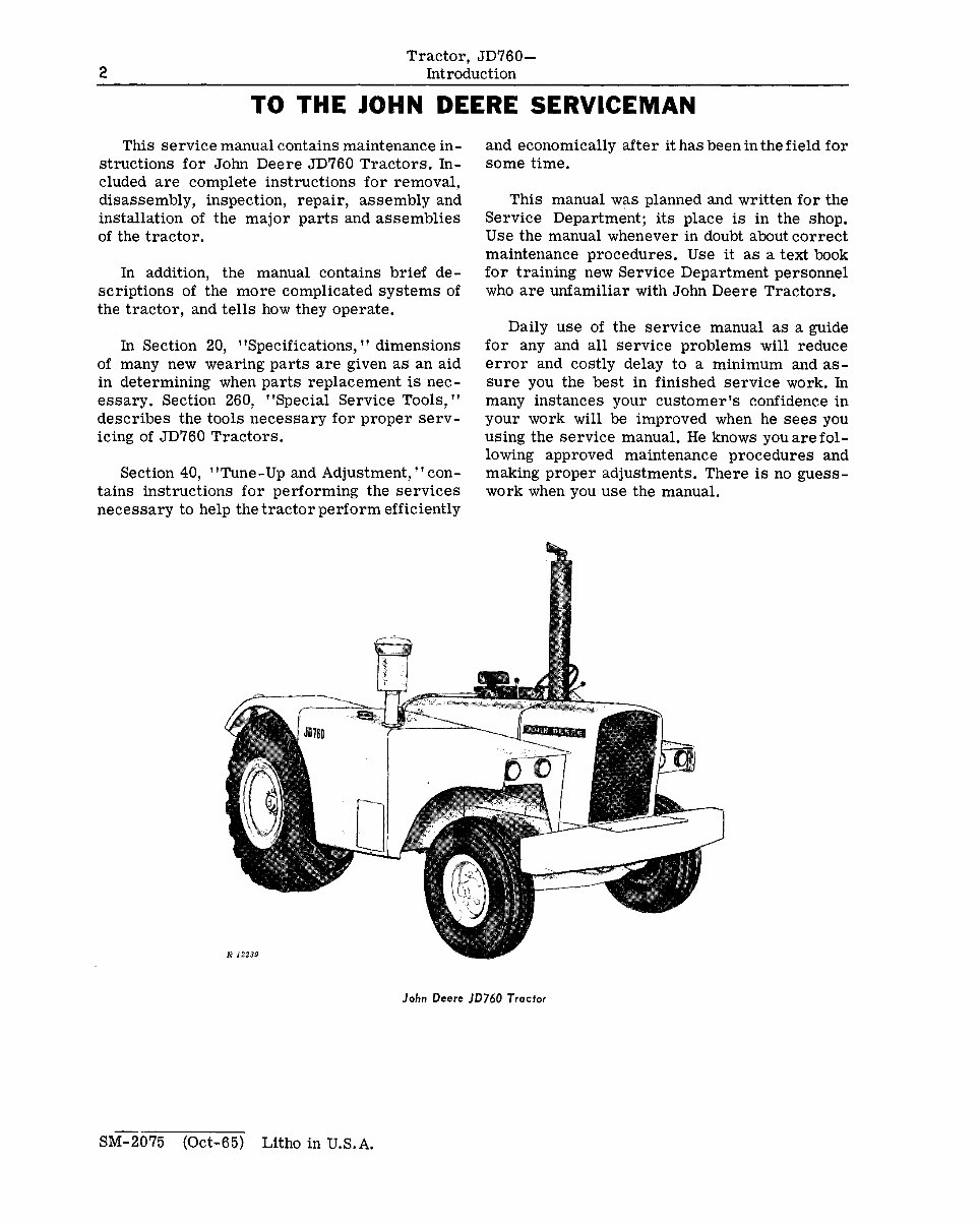
John Deere JD760 Tractor
SM-2075 (Ott-65) Litho in \U.S.A.
Group 5
DESCRiPTI
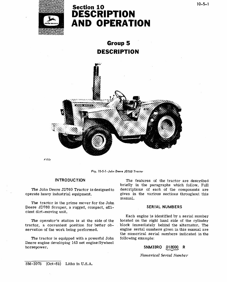
Fig. IO-5l-John Deere JD760 Tractor
INTRODUCTION
The John Deere JD760 Tractor is designed to
operate heavy industrial equipment.
The tractor is the prime mover for the John
Deere JD760 Scraper, a rugged, compact, effi-
cient dirt-moving unit.
The operator’s station is at the side of the
tractor, a convenient position for better ob-
servation of the work being performed.
The tractor is equipped with a powerful John
Deere engine developing 143 net engine flywheel
horsepower.
10-5-l
The features of the tractor are described
briefly in the paragraphs which follow. Full
descriptions of each of the components are
given in the various sections throughout this
manual.
SERIAL NUMBERS
Each engine is identified by a serial number
located on the right hand side of the cylinder
block immediately behind the alternator. The
engine serial numbers given in this manual are
the numerical serial numbers indicated in the
following example:
SNM33RO Pl~O~ R
Numerical Serial Number
SM-2075 (Ott-65) Litho in U.S.A.

10-5-2
Tractor, JD760-
Description and Operation Description
The tractor serial number is located at the
rear center of the transmission case. The trac-
tor serial numbers given in this manual are the
numerical serial numbers indicated in the fol-
lowing example:
SNT373R 012000 R
L I
Numerical Serial Number
NOTE: When ordering engine OY tractor
parts, record all the digits in the serialnumber.
For brevity, when serial numbers are given
in this manual any zeros which appear before
the first significant digit are omitted.
MODEL NUMBERS
The fuel injection pump, main hydraulic pump,
selective control valve housings, and alternator
each bear a model number.
ENGINE
The tractor is powered by a variable-speed,
full diesel engine. The engine develops up to 143
net engine flywheel horsepower at 2200 r-pm.
The engine is a six-cylinder in-line four-
stroke cycle engine. The cylinder liners are the
wet sleeve type and the crankshaft bearings are
the precision insert type.
Lubrication system has a full-flow filter with
a replaceable element. The engine oil cooler is
designed to cool the oil to a safe operating tem-
perature.
A liquid-seal impeller type crankcase venti-
lating pump draws clean air from the air clean-
er and circulates it throughthe engine for crank-
case ventilation.
COOLING SYSTEM
The pressure type cooling system has acen-
trifugal pump to provide continuous circulation
of engine coolant. Proper engine temperature is
maintained by two thermostats in the upper water
manifold.
When the thermostats are closed, thesystem
is designed to permit circulation of the coolant
through the engine without passing through the
radiator. This feature results in the engine
SM-2075 (Ott-65) Litho in U.S.A.
reaching operating temperature in a shorter
length of time. When the engine reaches operating
temperature, the thermostats open to control the
flow of coolant through the radiator to maintain
a constant operating temperature.
FUEL SYSTEM
A 72 U.S. gallon fuel tank is an integral part
of the fuel tank housing at the right side of the
tractor just ahead of the rear wheel.
A fuel pump driven by the camshaft assures a
constant supply of fuel to the injection pump.
Two replaceable micronic filtering elements
are connected between the fuel pump and the in-
j ection pump and filters the diesel fuel before it
enters the injection pump.
Fuel is injected by a distributor-type solid
injection pump through high-pressure nozzles
into the cylinders. A common pipe connected to
each nozzle returns leak-off fuel from the noz-
zles to the fuel tank.
ELECTRICAL SYSTEM
The tractor is equipped with a 24-volt alter-
nator with regulator to furnish current for the
electrical load and to maintain charges in four
B-volt batteries, connected in series.
This system is of the conventional grounded
type, using negative grounded circuits.
A 24-volt starting motor with a coaxial, sole-
noid-shifted drive pinion is used to crank the en-
gine.
Lighting circuits are 24-volt withtwo 12-volt
loads in series in each circuit. All lamps are in
pairs with exception of the tractor red taillamp
which is in series with a resistor. Current at 12
volts is furnished for the accessory circuit by
two of the four 6-volt tractor batteries.
CLUTCH ASSEMBLIES
The heavy-duty, two-plate, spring-loaded,
transmission clutch is located in a recess at rear
of the engine flywheel. It is operated by a pedal
(hydraulically assisted) located to the left ofthe
operator’s platform. The clutch-operating cyl-
inder is connected to an accumulator whichsup-
plies energy to operate the clutch, should the en-
gine be stopped or hydraulic pressure fail.
Tractor, JD760-
Descrintion and Oneration
10-S-3
The PTO clutch is of the multiple wet-disk
type and is hydraulically actuated. It is oper-
ated by a lever to right of operator.
TRANSMISSION
The Syncro-Range transmission, which con-
tains constant-mesh, helical-cut gears, has four
shift ranges. Three of the ranges have low, high,
and reverse gears. The fourth range has low and
high gears only. Thus, eight forward gears and
three reverse gears are provided. Shifting is
accomplished by means of two levers located to
the left and forward of the instrument panel. The
left-hand lever is used to select the desired
range. The right-hand lever is used to select
high, low, or reverse gear within the range.
The high, low, and reverse gear shifting is
synchronized and can be accomplished while the
tractor is moving.
While the shift between ranges is of the collar
shift type and is normally accomplished withthe
tractor stopped, it can be accomplished while
the tractor is on the move by proper use of the
“double clutching” technique.
DIFFERENTIAL AND FINAL DRIVE
A conventional spiral bevel ring gear and
pinion drive is used in the tractor. A planetary
gear assembly provides the final gear reduction
in the drive gear train. This design reduces
strain on the gear train.
A lock located in the differential assembly,
enables the operator to lock the differential.
This causes both rear wheels to turn at the
same speed, moving the tractor under conditions
where one drive wheel has lost its traction.
POWER TAKE-OFF (PTO)
The tractor can be furnished with a right-
angle, vertical PTO for use with the elevating
scraper. At 2200 engine rpm, the vertical PTO
operates at 1128 rpm.
The tractor can be obtained with a lOOO-rpm
horizontal PTO. At 1900 engine rpm, the hori-
zontal PTO operates at 1010 rpm.
DRAWBAR
The tractor is equipped with a heavy-duty
fixed drawbar for attaching towed equipment.
FRONT AXLE
The tractor is equipped with a heavy-duty,
fixed tread front axle. The front wheels are
truck-type rims bolted to hubs mounted on ta-
pered roller bearings.
Front wheel tread is 69-l/4 inches.
REAR WHEELS
Heavy-duty rear wheels are attached to the
rear axles with no provision for tread width
adjustment.
Rear wheel tread is 72 inches.
SEAT
The tractor is regularly equipped with a de-
luxe suspension seat. This seat contains a steel
compression spring and a shock absorber to pro-
vide “Float Ride” suspension.
The seat has a flexibly-mounted, padded back
rest and semi-circular foam padding which sur-
rounds the back of the operator.
S&I-2075 (Jun-67) Litho in U.S.A.
10-5-4
Tractor, JD760-
Description and Operation Description
HYDRAULIC SYSTEM
The tractor hydraulic system is pressurized
by a constant-running, variable displacement,
hydraulic pump. The pump is mounted below and
ahead of the radiator. It is driven at engine speed
by the engine crankshaft. The hydraulic pump
supplies oil under pressure to operate the power
steering, power brakes, transmission clutch,
differential lock, up to three remote hydraulic
cylinders (if so equipped) or, the brakes and
operating cylinders of trailing equipment.
The hydraulic system is constant pressure,
closed center, and “live”; that is, it operates
when the engine is running, whether the tractor
is moving or not.
STEERING
Hydraulic power steering is regular equip-
ment on the tractor. Movement of the steering
wheel actuates a steering valve which directs a
flow of pressure oil to two steering cylinders
which turn the front wheels. Should the hydraulic
system lose pressure, the tractor can be steered
manually.
POWER BRAKES
The power brakes are operated by pedals lo-
cated at the right side of the operator’s platform.
The brakes can be applied independently or si-
multaneously. The brake pedals can be locked
together for simultaneous operation if desired.
The hydraulically actuated, disk type brakes op-
erate in oil.
NOTE: The tractor brake pedals should al-
ways be locked together when operating the rock
wagon OY scraper unit except when it is neces-
savy to use individual braking to make extremely
shovt tuvns.
On scraper units, the scraper power brakes
are operated by a lever located at the left of the
steering column, just under the steering wheel.
On tractors with Athey Rock Wagons, this lever
is the brake selector lever and controls the op-
eration of the rock wagon brakes.
CAUTION: Always apply the scraper brakes
f Ir st when stopping the unit. Then, if necessary,
use tractor brakes to assist. Using tractor
brakes alone can be dangerous due to possible
jackknifing of the unit.
A brake accumulator, charged with dry nitro-
gen at 500 psi pressure, is connected to the
brake systems and transmission clutch operating
cylinder.
The accumulator stores energy for operation
of brakes and clutch for several applications
after the engine is stopped or if the main hy-
draulic pump should fail.
Units with the selective control valve levers
running crosswise to the tractor also have a hy-
draulic oil accumulator that is connected to the
selective control valve circuits. The hydraulic
oil accumulator is also charged with dry nitro-
gen at 500 psi pressure.
SM-2075 (Jun-67) Litho in U.S.A.
Operation
Tractor, JD760-
Description and Operation 10-10-l
STARTING CONTROLS
Group 10
OPERATION
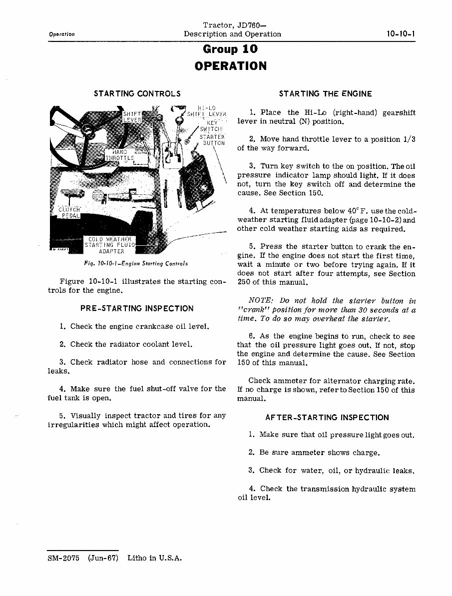
Fig. IO-IO-I-Engine Starting Controls
Figure 10-10-l illustrates the starting con-
trols for the engine.
PRE-STARTING INSPECTION
1. Check the engine crankcase oil level.
2. Check the radiator coolant level.
3. Check radiator hose and connections for
leaks.
4. Make sure the fuel shut-off valve for the
fuel tank is open.
5. Visually inspect tractor and tires for any
irregularities which might affect operation.
STARTING THE ENGINE
1. Place the Hi-Lo (right-hand) gearshift
lever in neutral (N) position.
2. Move hand throttle lever to a position l/3
of the way forward.
3. Turn key switch to the on position. The oil
pressure indicator lamp should light. If it does
not, turn the key switch off and determine the
cause. See Section 150.
4. At temperatures below 40” F. use the cold-
weather starting fluid adapter (page 10-10-2) and
other cold weather starting aids as required.
5. Press the starter button to crank the en-
gine. If the engine does not start the first time,
wait a minute or two before trying again. If it
does not start after four attempts, see Section
250 of this manual.
NOTE: Do not hold the starter button in
“wank” position for moye than 30 seconds at a
time. To do so may overheat the starter.
6. As the engine begins to run, check to see
that the oil pressure light goes out. If not, stop
the engine and determine the cause. See Section
150 of this manual.
Check ammeter for alternator charging rate.
If no charge is shown, refer to Section 150 of this
manual.
AFTER-STARTING INSPECTION
1. Make sure that oil pressure light goes out.
2. Be sure ammeter shows charge.
3. Check for water, oil, or hydraulic leaks.
4. Check the transmission hydraulic system
oil level.
SM-2075 (Jun-67) Litho in U.S.A.
10-10-2
Tractor, JD760-
Description and Operation Operation
COLD WEATHER STARTING
COLD WEATHER STARTING FLUID ADAPTER
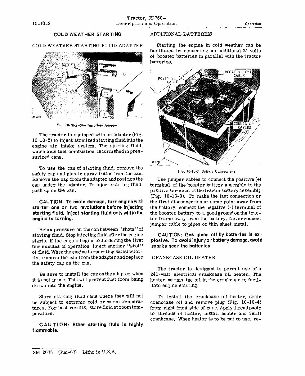
Fig. IO-IO-2-Starting Fluid Adapter
The tractor is equipped with an adapter (Fig.
10-10-2) to inject atomizedstartingfluidintothe
engine air intake system, The starting fluid,
which aids fuel combustion, is furnished in pres -
surized cans.
To use the can of starting fluid, remove the
safety cap and plastic spray buttonfrom the can.
Remove the cap from the adapter and position the
can under the adapter. To inject starting fluid,
push up on the can.
CAUTION: To avoid damage, turn engine with
starter one or two revolutions before injecting
startlng fluld. InJect starting fluld only while the
engine Is turnlng.
Relax pressure on the canbetween “shots”of
starting fluid. Stop injecting fluid after the engine
starts. If the engine begins to die during the first
few minutes of operation, inject another “shot”
of fluid. When the engine is operating satisfactor -
ily, remove the can from the adapter and replace
the safety cap on the can.
Be sure to install the cap on the adapter when
it is not inuse. This will prevent dust from being
drawn into the engine.
Store starting fluid cans where they will not
be subject to extreme cold or warm tempera-
tures. For best results, store fluid at room tem-
perature.
CAUTION: Ether startlng fluld Is highly
flammable.
ADDITIONAL BATTERIES
Starting the engine in cold weather can be
facilitated by connecting an additional 24 volts
of booster batteries in parallel with the tractor
batteries.
Ri
i-’ / /
Fig. IO-70-3-Battery Connections
Use jumper cables to connect the positive (+)
terminal of the booster battery assembly to the
positive terminal of the tractor battery assembly
(Fig. 10-10-3). To make the last connection or
the first disconnection at some point away from
the battery, connect the negative (-) terminal of
the booster battery to a good groundon the trac-
tor frame away from the battery. Never connect
jumper cable to pipes or thin sheet metal.
CAUTION: Gas glven off by batteries Is ex-
ploslve. To avold Injury or battery damage, avoid
sparks near the batteries.
CRANKCASE OIL HEATER
The tractor is designed to permit use of a
240-watt electrical crankcase oil heater. The
heater warms the oil in the crankcase to facil-
itate engine starting.
To install the crankcase oil heater, drain
crankcase oil and remove plug (Fig. 10-10-4)
from right front side of case. Apply thread paste
to threads of heater, install heater and refill
crankcase. When heater is to be put to use, re-
SM-2075 (Jun-67) Litho in U.S.A.
You're Reading a Preview
What's Included?
Fast Download Speeds
Online & Offline Access
Access PDF Contents & Bookmarks
Full Search Facility
Print one or all pages of your manual
$57.99
Viewed 18 Times Today


Secure transaction
What's Included?
Fast Download Speeds
Online & Offline Access
Access PDF Contents & Bookmarks
Full Search Facility
Print one or all pages of your manual
$57.99
Get the John Deere 760 Tractor Service Manual SM-2075 in PDF format. This manual is an essential resource for both professional mechanics and DIY enthusiasts. It contains 390 pages of technical information, specifications, diagrams, and real photo illustrations. The manual is indispensable for diagnosing, repairing, and maintaining John Deere machinery.
Key features include:
- Description and Operation
- Specifications
- Lubrication and Periodic Services
- Engine Tune-Up and Tractor Adjustment
- Preliminary Procedure for Major Service
- Engine
- Engine Lubrication System
- Cooling System
- Diesel Fuel System
- Transmission Clutch
- Syncro-Range Transmission
- Differential
- Final Drive System
- Power Take-Off (PTO)
- Electrical System
- Seat
- Front Axle
- Wheels, Tires and Weights
- Hydraulic System
- Hydraulic Pumps
- Power Steering
- Power Brakes
- Selective Control Valves
- Drawbar Assembly
- Trouble Shooting
- Special Service Tools
This PDF manual offers the advantage of a search feature in Acrobat, allowing you to quickly find the information you need and print specific pages or the entire manual. Contact us if you have any questions or if there's a specific manual you've been searching for. Have a great day!


